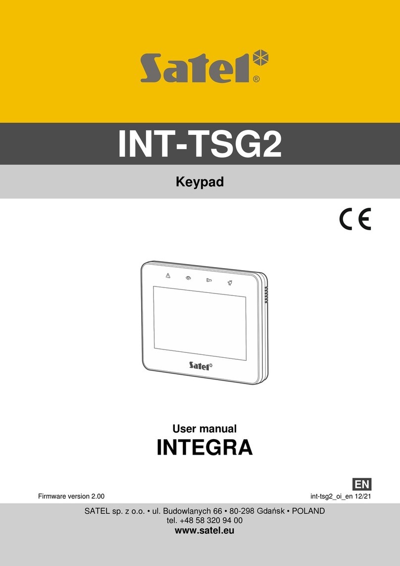
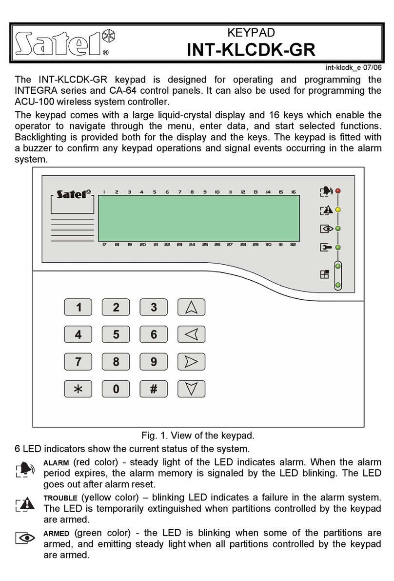
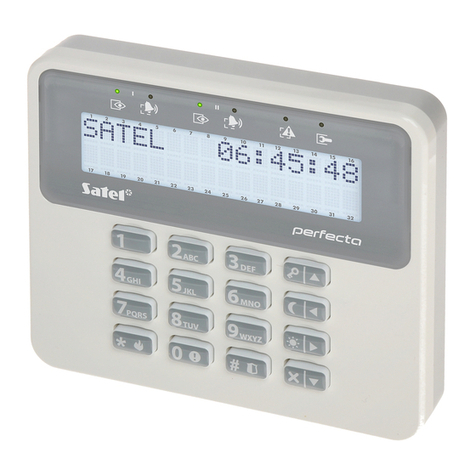
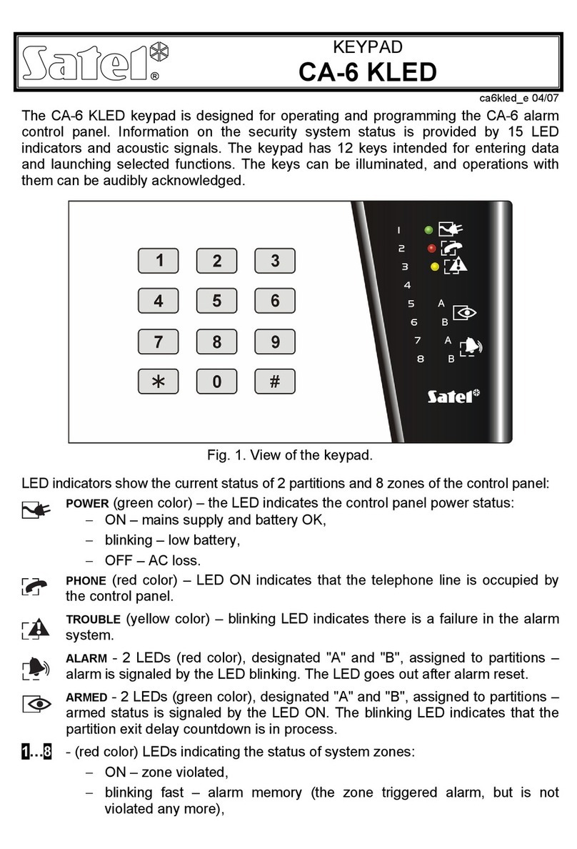
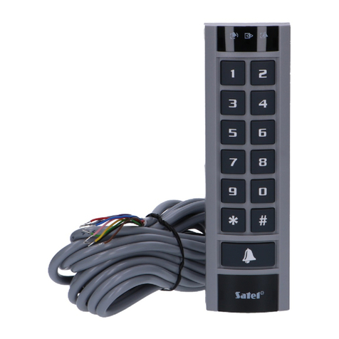
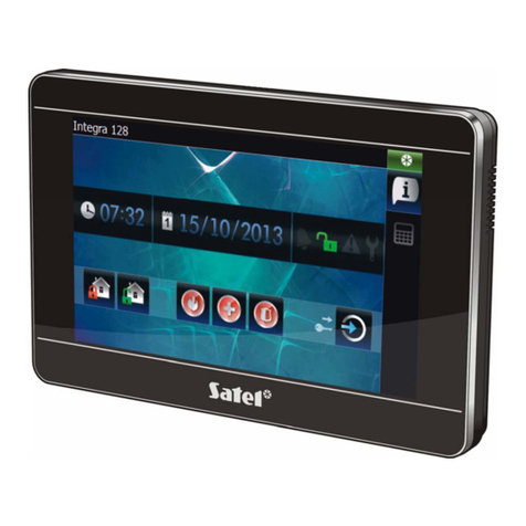
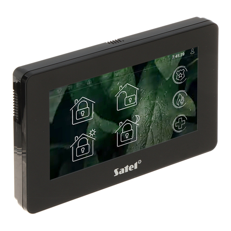
Satel INT-TSG User guide

int-tsg_i_en 06/15
Keypad
INT-TSG
Installer Manual
Firmware version 1.03
SATEL sp. z o.o. • ul. Budowlanych 66 • 80-298 Gdańsk • POLAND
tel. 58 320 94 00
www.satel.eu

WARNINGS
The keypad should be installed by qualified personnel.
Read carefully this manual before proceeding to installation.
Changes, modifications or repairs not authorized by the manufacturer shall void your rights
under the warranty.
SATEL's goal is to continually upgrade the quality of its products, which may result in
alterations of their technical specifications and firmware. The current information on
the introduced modifications is available on our website.
Please visit us:
http://www.satel.eu
The declaration of conformity may be consulted at www.satel.eu/ce
The following symbols may be used in this manual:
- note;
- caution.

CONTENTS
1. Introduction......................................................................................................................2
2. Features ..........................................................................................................................2
3. Installation and hook-up ..................................................................................................2
3.1 Description of terminals .............................................................................................4
4. Addressing ......................................................................................................................4
4.1 Keypad connected to INTEGRA / INTEGRA Plus control panel................................4
4.1.1 Programming keypad address by means of service function .............................4
4.2 Keypad connected to VERSA / VERSA Plus control panel .......................................5
4.2.1 Programming keypad address by means of service function .............................5
4.3 Programming address without entering the service mode.........................................5
5. Keypad identification .......................................................................................................5
5.1 Keypad connected to INTEGRA / INTEGRA Plus control panel................................6
5.2 Keypad connected to VERSA / VERSA Plus control panel .......................................6
6. microSD memory card..................................................................................................... 6
6.1 Inserting the microSD card ........................................................................................6
6.2 Removing the microSD card......................................................................................7
7. Keypad configuring..........................................................................................................7
7.1 Keypad connected to INTEGRA / INTEGRA Plus control panel................................7
7.1.1 Keypad ...............................................................................................................7
7.1.2 State inspections ..............................................................................................11
7.1.3 User functions definition ...................................................................................12
7.1.4 Macro commands.............................................................................................12
7.1.5 Status screen ...................................................................................................17
7.1.6 End-of-line resistance....................................................................................... 19
7.2 Keypad connected to VERSA / VERSA Plus control panel .....................................20
7.2.1 Parameters and options ...................................................................................20
7.2.2 Status screen ...................................................................................................23
8. Updating the keypad firmware....................................................................................... 24
9. Specifications ................................................................................................................25
10. Manual update history ...................................................................................................26

2 INT-TSG SATEL
1. Introduction
The INT-TSG keypad allows operation and programming of the INTEGRA, INTEGRA Plus,
VERSA and VERSA Plus control panels. This manual applies to the keypad with firmware
version 1.03, which is supported by the following control panels:
INTEGRA and INTEGRA Plus with firmware version 1.13 or newer,
VERSA and VERSA Plus with firmware version 1.04 or newer.
For programming of keypad, the D
LOAD
X program version 1.13.004 or newer is required.
Changes made to the firmware version 1.03
Keypad volume control by the user through the graphic interface.
Ability to display slide show / clock as a screensaver after 10 minutes' inactivity of the
keypad.
Ability to define response of the keypad to wake-up (after a tap on the screen by the user
or occurrence of a specified event in the system).
Compatibility with the VERSA and VERSA Plus control panels.
2. Features
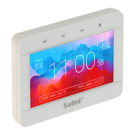
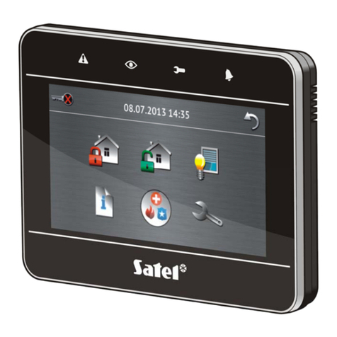
4.3" touch screen.
Intuitive icon-based menu.
Alarm system control by means of macro commands to start a number of different
functions in the control panel.
Customizable status screen.
Display of slide show as a background of the status screen.
LEDs indicating the state of partitions and system.
Built-in reader of microSD memory cards.
Built-in sounder.
2 programmable hardwired zones (supported if the keypad is connected to INTEGRA /
INTEGRA Plus):
– support for NO and NC type detectors, as well as roller shutter and vibration detectors;
– support for Single EOL, Double EOL and Triple EOL configuration (Triple EOL when
working with INTEGRA Plus control panels);
– programming end-of-line resistor values.
Tamper contact reacting to the enclosure opening or detaching from the wall.
3. Installation and hook-up
Disconnect power before making any electrical connections.
The INT-TSG keypad is designed for indoor installation. The place of installation should be
readily accessible to the system users.
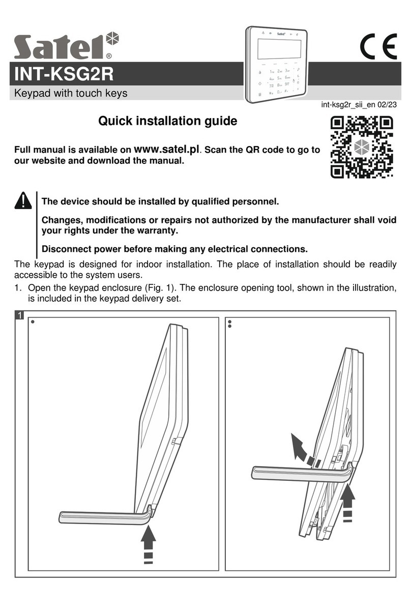
1. Open the keypad enclosure (see Fig. 1). The enclosure opening tool, shown in the
illustration, is included in the keypad delivery set.
2. Place the enclosure base on the wall and mark the location of mounting holes. Be sure to
take into account the tamper element mounting hole.
3. Drill the holes for wall plugs (screw anchors).

SATEL INT-TSG 3
4. Pass the cables through the opening in the enclosure base.
5. Using wall plugs (screw anchors) and screws, fasten the enclosure base to the wall.
6. Connect the DTM, CKM and COM keypad terminals to the appropriate terminals of the
control panel communication bus (see Fig. 2). It is recommended that the unshielded non-
twisted cable be used for making the connection. If you use the twisted-pair type of cable,
remember that CKM (clock) and DTM (data) signals must not be sent through one
twisted-pair cable. The wires must be run in one cable. The length of cables must not
exceed 300 m.
Fig. 1. Opening the enclosure.
Fig. 2. Connection of the keypad to the control panel.
7. Connect the wires to the terminals of additional zones, if any detectors are to be
connected to them (the detectors are to be connected in the same way as to the control
panel onboard zones).

4 INT-TSG SATEL
8. Connect the supply wires to the KPD and COM terminals. The keypad can be powered
directly from the control panel, from expander with power supply or from a power supply
unit.
9. Place the front panel onto the catches, snap close the enclosure.
3.1 Description of terminals
KPD - power supply input.
COM - common ground.
DTM - data.
CKM - clock.
A RS485 B - unused terminals.
Z1, Z2 - zones.
4. Addressing
Each keypad connected to the control panel must have its individual address set on it. By
default, address 0 is set in the keypad.
When started, only the control panel with factory default settings can provide support
for all keypads connected to the bus, irrespective of the addresses set in them. In all
other cases, the control panel will block operation of the keypads having identical
addresses.
4.1 Keypad connected to INTEGRA / INTEGRA Plus control panel
The keypad must have an address set in it:
from the 0 to 3 range, if it is connected to the INTEGRA 24 or INTEGRA 32 control panel;
from 0 to 7 range, if it is connected to another INTEGRA or INTEGRA Plus control panel.
The address set in the keypad determines the numbers to be given to the keypad zones (see
the I
NSTALLER MANUAL
for INTEGRA or INTEGRA Plus control panels).
4.1.1 Programming keypad address by means of service function
1. Tap on the main screen. The “Advanced” screen will be displayed.
2. Tap . The terminal will be displayed.
3. Enter the service code (by default: 12345) and tap . The user menu will be
displayed.
4. Tap . The service mode will start up.
5. Start the K
EYPADS ADDR
. function (S
TRUCTURE
H
ARDWARE
I
DENTIFICATION
K
EYPADS
ADDR
.). The “This LCD address (n, 0-x)” message will appear on the displays of all
keypads connected to the control panel (n – keypad address; 0-x – range of supported
addresses).
6. Tap the key with the digit corresponding to the address which is to be programmed on the
keypad.
7. To terminate the address change function, tap . The function will be terminated
automatically after 2 minutes from being started. Termination of the function will restart

SATEL INT-TSG 5
the keypad (the service mode menu will be displayed on the keypad with the lowest
address).
4.2 Keypad connected to VERSA / VERSA Plus control panel
An address from within the 0 do 5 range must be set on the keypad.
4.2.1 Programming keypad address by means of service function
1. Tap on the main screen. The “Advanced” screen will be displayed.
2. Tap . The terminal will be displayed.
3. Enter the service code (by default: 12345) and tap . The user menu will be
displayed.
4. Tap in turn . The service mode will start up.
5. Tap in turn . The K
EYPADS ADDR
. function will start. On all
keypads, LEDs designated by icons will start blinking and current address information will
be presented.
6. Tap the key with the digit corresponding to the address which is to be programmed on the
keypad.
7. To terminate the address change function, tap . The function will be terminated
automatically after 2 minutes from being started. Termination of the function will restart
the keypad.
4.3 Programming address without entering the service mode
This way of address programming is useful when the keypad operation is blocked and
starting the service mode is impossible. It can be used irrespective of which control panel the
keypad is connected to.
1. Turn off keypad power supply.
2. Disconnect wires from the keypad terminals CKM and DTM.
3. Short the keypad terminals CKM and DTM.
4. Turn on keypad power supply. A message indicating the current address will appear on
the display.
5. Tap the key with the digit corresponding to the address which is to be programmed on the
keypad.
6. Turn off keypad power supply.
7. Open the keypad terminals CKM and DTM.
8. Connect wires, as required, to the keypad terminals CKM and DTM.
9. Turn on keypad power supply.
5. Keypad identification
The alarm system can only be programmed and operated from keypads that have been
identified by the control panel. The keypad identification function should be executed at the
first start-up of the control panel, and then each time when adding a new keypad or changing
address in a keypad supported by the control panel. Disconnecting an identified keypad from
the bus will trigger the tamper alarm.

6 INT-TSG SATEL
5.1 Keypad connected to INTEGRA / INTEGRA Plus control panel
The identification function can be run by using:
LCD keypad: S
ERVICE MODE
S
TRUCTURE
H
ARDWARE
I
DENTIFICATION
LCD
KEYPADS
ID
. How to enter the service mode, refer to section on programming keypad address by
means of the service function (p. 4).
D
LOAD
X program: “Structure” window “Hardware” tab “Keypads” item “Keypads
identification” button.
5.2 Keypad connected to VERSA / VERSA Plus control panel
To run the identification function for keypads and expanders you can use:
keypad: S
ERVICE MODE
2. H
ARDWARE
1. K
PDS
.
&
EXPS
. 1. I
DENTIFICAT
. How to enter
the service mode, refer to the section on programming keypad address by means of the
service function (p. 5).
D
LOAD
X program: “Versa – Structure” window “Hardware” tab “Expanders” branch
“Identification” button.
6. microSD memory card
On the microSD memory card:
you can put the additional macro command icons;
you can put photos which will be used for the slide show;
you should put the file with a new version of the keypad firmware, if the firmware is to be
updated.
The keypad supports the microSD and microSDHC memory cards.
The microSD memory card should be purchased separately.
Inserting and removing the memory card requires opening of the keypad enclosure, so
if the alarm system is working, remember to start the service mode.
6.1 Inserting the microSD card
Fig. 3. Installing the microSD memory card.

SATEL INT-TSG 7
1. Open the keypad enclosure (see: Fig. 1).
2. Insert the card into its slot (see Fig. 3) and push until it clicks into place. The card contacts
should be directed toward the display.
3. Close the keypad enclosure.
6.2 Removing the microSD card
1. Open the keypad enclosure (see: Fig. 1).
2. Push the card to release it.
3. Remove the card from its slot.
7. Keypad configuring
7.1 Keypad connected to INTEGRA / INTEGRA Plus control panel
To configure the keypad settings you can use:
D
LOAD
X program: “Structure” window “Hardware” tab “Keypads” branch [keypad
name]. The D
LOAD
X program alone makes it possible to configure all the settings.
LCD keypad: S
ERVICE MODE
S
TRUCTURE
H
ARDWARE
LCD
KEYPADS
S
ETTINGS
[keypad name]. How to enter the service mode, refer to the section on programming
keypad address by means of the service function (p. 4).
7.1.1 Keypad
Shown in square brackets are the names displayed on keypads.
Name – individual name of the keypad (up to 16 characters).
Partitions managed by keypad [Partitions] – the partitions which can be armed/disarmed or
alarm in which may be cleared from the keypad. These functions are available to the users
having a suitable authority level and access to those partitions.
Using the service code you can operate all partitions, irrespective of which partitions
are operated by the keypad.
Show alarms of partitions [Alarms] – the keypad can signal burglary alarms from selected
partitions.
Show fire alarms of partitions [Fire alarms] – the keypad can signal fire alarms from
selected partitions.
CHIME signal of zones [Chime zones] – the keypad can audibly signal violation of selected
zones. If the zone is armed, violation will not trigger the CHIME signal.
Zone disabling CHIME [Chime bps. zone] – zone, which, if violated, will disable the CHIME
feature for specified time.
Bypass time [Chime bps. time] – time during which the CHIME signal will be disabled after
violation of the zone which disables the signaling (time is counted from the zone restore). If
the value 0 is programmed, the signaling will not be disabled.
Quick Arm partitions [Quickarm part.] – partitions which can be armed without entering the
code (quick arming).
Show entry delay of partitions [Entry time p.] – the partitions, for which counting the entry
delay will be indicated by text appearing on the display.
Show exit delay of partitions [Exit time part.] – the partitions for which counting the exit
delay will be indicated by text appearing on the display.

8 INT-TSG SATEL
Date/Time format – the way the time and date are displayed on the keypad main screen and
on the terminal.
Alarm messages
Partitions [Part.alarm msg.] – if this option is enabled, messages on partition alarms will be
displayed (they contain the name of partition).
Zones [Zone alarm msg.] – if this option is enabled, messages on alarms from zones will be
displayed (they contain the name of zone). The zone alarm messages have the priority.
Alarms
FIRE [Fire alarm] – if this option is enabled, you can trigger fire alarm from the keypad by
tapping and holding for 3 seconds:
– on the “Emergency” screen,
– on the terminal.
PANIC [Panic alarm] – if this option is enabled, you can trigger panic alarm from the keypad
by tapping and holding for 3 seconds:
– on the “Emergency” screen,
– on the terminal.
AUX. [Medical alarm] – if this option is enabled, you can trigger medical alarm from the
keypad by tapping and holding for 3 seconds:
– on the “Emergency” screen,
– on the terminal.
3 wrong codes [3 wrong codes] – if this option is enabled, entering incorrect code three
times will trigger the alarm.
Additional options
Silent PANIC alarm [Silent panic] – if this option is enabled, the panic alarm triggered from
the keypad will be a silent one (without loud signal). Additionally, the silent panic alarm can
be triggered by tapping and holding any part of the status screen for about 3 seconds. The
option is available, if the PANIC
option is enabled.
Sign. entry delay [Entry time s.] – with this option enabled, the keypad will audibly signal the
entry delay countdown.
Sign. exit delay [Exit time sig.] – with this option enabled, the keypad will audibly signal the
exit delay countdown.
Sign. alarms [Alarm signal.] – with this option enabled, the keypad will signal the alarms
audibly.
Key sounds – when this option is enabled, tapping the keypad screen is confirmed by a
beep.
Sign. trbl. in part. arm [Trbl. in p.arm.] – with this option enabled, the keypad signals
troubles by means of the LED, if some of the operated partitions are armed (the
troubles are not signaled if all partitions are armed).
Sign. new trouble [New trbl. sign.] – with this option enabled, the keypad can audibly signal
the occurrence of a new trouble (additionally, the T
ROUBLE MEMORY UNTIL REVIEW
option
must be enabled in the control panel – see: control panel programming manual). New
trouble signaling is cleared after the troubles have been reviewed by the user.
SATEL INT-TSG 9
Show code entering [Show code ent.] – with this option enabled, entering the code is
presented on the keypad display by asterisks.
Fig. 4. D
LOAD
X program: parameters and options of keypad connected to INTEGRA /
INTEGRA Plus control panel.
Exit delay clearing enable [Fin. exit time.] – with this option enabled, the exit delay time in
partitions with the E
XIT DELAY CLEARING
option enabled can be shortened by means of:
– macro command;
– terminal (after tapping in turn the and keys).

10 INT-TSG SATEL
Show viol. zones [Zone violation] – with this option enabled, violating the CHIME signal
triggering zone result additionally in the zone name being displayed.
Auto-Arm delay countdown [Auto-arm delay] – with this option enabled, the auto-arm delay
countdown in partition is signaled acoustically.
Show disarm messages [Show disarming] – if this option is enabled, the keypad will inform
about disarming with a displayed message at all times. If the option is disabled – only in
case of disarming from the given keypad.
Show arm messages [Show arm] – if this option is enabled, the keypad will inform about
arming with a displayed message (irrespective of how the system was armed).
Quick control [Control (8#)] – if this option is enabled, the O
UTS CONTROL
user function can
be started without entering the user code:
– after tapping the icon on the main screen, if no macro command is assigned to the
group;
– after tapping and holding the icon on the main screen for about 3 seconds, if at
least one macro command is assigned to the group;
– from the terminal, after you tap in turn the and keys.
Zones
For each of the keypad zones can be defined whether it will be used or not.
Auto-backlight
The keypad can be woken up after occurrence of a specified event in the system: starting the
entry delay countdown in a selected partition, or violating a selected zone.
Wake-up
You can define how the keypad will respond to the wake-up (after a tap on the screen by the
user or occurrence of a specified event in the system):
Status screen – status screen will be displayed.
Menu screen – main screen will be displayed.
Disarming – if at least one partition managed by the keypad is armed, the authorization
screen will be displayed (after entering the code and tapping , and depending on the
system state: the partition(s) will be disarmed / partition selection screen will be displayed /
“Alarm clearing / Disarming” screen will be displayed). If none of the partitions is armed,
the main screen will be displayed.
Photo frame – if this option is enabled, the following will be displayed after 10 minutes of
keypad inactivity:
slide show – if there are at least two pictures on the memory card and the value of
C
HANGE PICTURE EVERY
parameter is different from 0,
clock – if there are one or no pictures on the memory card or the value of C
HANGE PICTURE
EVERY
parameter is 0.
If this option is disabled, the screen will go blank after 10 minutes of keypad inactivity.
Tamper signaled in part. [Tamper in part.] – partition where alarm will be triggered in the
event of keypad tamper (opening the enclosure or disconnecting keypad from the bus).

SATEL INT-TSG 11
7.1.2 State inspections
Fig. 5. D
LOAD
X program: “State inspections” tab.
1 – zone state [Zones] – if this option is enabled, you can inspect the zone state without
entering the code:
– after tapping on the “System status” screen,
– after tapping and holding for 3 seconds on the terminal.
4 – partitions armed [Partitions] – if this option is enabled, you can inspect the partition state
without entering the code:
– after tapping on the “System status” screen,
– after tapping and holding for 3 seconds on the terminal.
5 – alarm events memory [Alarms log] – if this option is enabled, you can view the alarms
log without entering the code:
– after tapping on the “System status” screen,
– after tapping and holding for 3 seconds on the terminal.
6 – trouble memory [Troubles log] – if this option is enabled, you can view the troubles log
without entering the code:
– after tapping on the “System status” screen,
– after tapping and holding for 3 seconds on the terminal.

12 INT-TSG SATEL
7 – trouble status [Troubles] – if this option is enabled, you can view the current troubles
without entering the code:
– after tapping on the “System status” screen,
– after tapping and holding for 3 seconds on the terminal.
8 – chime on/off [Chime changing] – if this option is enabled, the user can switch on/off the
CHIME signal in the keypad by means of the terminal, tapping and holding for about 3
seconds on the terminal.
Zone state [Zone characters] – you can define the symbols which will be used by the
terminal to illustrate the state of zones.
Partition state [Part. characters] – you can define the symbols which will be used by the
terminal to illustrate the state of partitions.
7.1.3 User functions definition
Code+arrows – you can define which functions will be started on entering the code and
tapping the selected arrow key.
7.1.4 Macro commands
The macro commands related data are stored in the keypad memory. Before you start
defining the macro commands, click on the “Read” button in the “Macro commands”
tab to read the data from the keypad. Having defined the macro commands, click on
the “Write” button in the “Macro commands” tab to write the data to the keypad. The
macro command related data are not read / written when you click on the button
in the main menu of D
LOAD
X program.
In the keypad with factory default settings, there are two macro commands defined
which are assigned to the first group:
0# – quick full arming (the control panel will only execute the macro command after
you define the partitions which are to be armed in the event of quick full arming –
see Q
UICK
A
RM PARTITIONS
p. 7);
9# – exit delay clearing (the control panel will execute the macro command if reducing
the exit delay time is allowed by the partition settings and the E
XIT DELAY CLEARING
ENABLE
option is enabled in the keypad – see p. 9).
The “Reset” button in the D
LOAD
X program makes it possible to restore the keypad
factory settings, i.e. those related to macro commands, status screen and EOL
resistors (in the case of the keypads supported by the INTEGRA Plus control panels,
the EOL resistor values are not programmed individually for keypad zones).
Groups
The macro commands which are to be available for the keypad users must be assigned to
one of the four groups. Up to 16 macro commands can be assigned to a group. Up to 6
macro command icons can be displayed on the keypad screen at the same time. The
D
LOAD
X program presents groups of macro commands and macro commands assigned to
them in a tree form.
Name – name of the macro command group which is displayed on the keypad screen under
the icon (up to 16 characters in two lines, up to 8 characters in the line). Do not enter the
name if it is not to be displayed.

SATEL INT-TSG 13
Icon – icon of a group of macro commands. In order to display the list of available icons, click
the button.
Fig. 6. D
LOAD
X program: “Groups” tab.
Macro available on the status screen – if this option is enabled, the group of macro
commands is available from the status screen, i.e. touching a corner of the status screen
will display macro commands assigned to that group (1
st
group of macro commands –
upper left corner; 2
nd
group of macro commands – upper right corner; 3
rd
group of macro
commands – lower left corner; 4
th
group of macro commands – lower right corner).
Icon visible on the status screen – if this option is enabled, the icon of the group of macro
commands is displayed in the corresponding corner of the status screen. The option is
available when the M
ACRO AVAILABLE ON THE STATUS SCREEN
option is enabled for the group
of macro commands.
Add macro – the button is available after you click on a group of macro commands. It
displays a list containing the names of defined macro commands. After you click on
a name, the macro command will be added to the group.
Remove macro – the button is available after you click on any macro command. It removes
that macro command from the group.
– click to move the highlighted macro command down within the group.
– click to move the highlighted macro command up within the group.
Read – click to read the macro command related data from the keypad.
Write – click to write the macro command related data to the keypad.

14 INT-TSG SATEL
Quit – click to cancel reading or writing the macro command related data.
Reset – click to delete all the defined macro commands (and restore factory default settings).
Export to file – click to export defined macro commands to a file. The file with macro
commands can be imported to another INT-TSG keypad.
Import from file – click to import macro commands from a file.
Save icons on SD card – click to write icons to the microSD memory card (all icons
available in the D
LOAD
X program will be written). The microSD card must be inserted in the
computer memory card reader (after clicking the button, indicate the card location).
Definitions
Fig. 7. D
LOAD
X program: “Definitions” tab.
You can create and configure macro commands in the “Definitions” tab. The macro command
is a sequence of actions, composed of single commands, which are to be done by the control
panel when running the macro command.
New macro – click to create a new macro command.
Remove macro – click to delete selected macro command.
Name – individual name of the macro command (up to 16 characters in two lines, up to 8
characters in the line).
Code – the code which is to be used for authorization when executing commands contained
in the macro command. For execution of such commands to be possible, the code must be
granted a suitable authority level. It is presented as a string of asterisks.
If, when running a macro command, it turns out that the code is invalid (e.g. it has
been changed in the meantime), the user will be able to enter the correct code. It will
be automatically saved to the keypad memory (replacing the invalid one).

SATEL INT-TSG 15
Authorization required – if this option is enabled, the macro command will only be run after
user authorization by using a code. The code entered in the “Code” field will be ignored.
Disabled if armed – if this option is enabled, the macro command will not be available, when
any of the partitions operated by the keypad is armed.
Autoexecute – if this option is enabled and the group contains just one macro command, the
macro command will run immediately on tapping the icon of macro command group (or the
status screen corner, if the M
ACROS AVAILABLE ON THE STATUS SCREEN
option is enabled). If
the A
UTHORIZATION REQUIRED
option is enabled, authorization with code will be necessary.
No confirmation messages – if this option is enabled, no messages will appear to inform
you about execution of a command or an error after running a macro command (the
screen from which the macro command was run will still be displayed).
Icon – the macro command icon. The list of available icons will be displayed after you click
the button. If the S
TATE FOLLOW OUTPUT
option is enabled, select 2 icons for the macro
commands. One icon will be displayed when the output is inactive, and the other – when
the output is active.
State follow output – if this option is enabled, the icon of macro command will change
depending on the status of output whose number should be selected in the field on the
right side. Select an output, the status of which depends on the actions taken by the
control panel after running the macro command. Thus it will be possible to inform the
user by means of macro command icons about, for example, the status of outputs
controlled by using macro commands or the status of partitions which are armed by
a macro command.
Show name – if this option is enabled, the macro command name will be displayed on the
keypad below the icon.
Commands list – commands assigned to the currently highlighted macro command. The
and buttons allow you to change the order of commands (moving the selected
command up and down).
Add – click to add to the list a new command, selected in the “Command” field.
Change – click to save the changes to the command parameters which were made after
adding the command to the list (otherwise, the changes made will not be saved).
Delete – click to remove the highlighted command from the list.
Command – the control panel executed function which can be assigned to the macro
command. The list of all available functions will be displayed after you click the button.
Depending on which function you choose:
Arming – select the partitions which are to be armed (double-click on the field designated
by the partition number) and define the arming mode (next clicks on the field designated
by the partition number; the digit inside the field has the following meaning: 0 - fully
armed; 1 – fully armed+bypasses; 2 – armed without interior; 3 - armed without interior
and without entry delay).
Disarming – select the partitions which are to be disarmed (double-click on the field
designated by the partition number).
Alarm clearing – select the partitions in which alarm is to be cleared (double-click on the
field designated by the partition number).
Bypass zones – select the zones which are to be inhibited (double-click on the field
designated by the zone number).
Unbypass zones – select the zones which are to be unbypassed (double-click on the field
designated by the zone number).

16 INT-TSG SATEL
Outputs ON – select the outputs which are to be activated (double-click on the field
designated by the output number).
Outputs OFF – select the outputs which are to be deactivated (double-click on the field
designated by the output number).
Change outputs state – select the outputs whose status is to be changed (double-click
on the field designated by the output number).
KNX telegram – program the following parameters of KNX telegram for the INT-KNX
module:
INT-KNX module – INT-KNX module which is to send the telegram.
Group address – the group address which will be inserted in the telegram.
Type – the telegram type.
Value – the value that will be inserted in the telegram (parameter available for some
types of the telegram).
Priority – telegram priority (if two elements of the bus start transmitting simultaneously,
the telegram with higher priority will be sent first).
KNX telegram (v2) – program the following parameters related to setting the value of KNX
communication object:
Module INT-KNX – INT-KNX-2 module in which the value is to be set.
Makro Command – name of the V
IRTUAL
(
MACRO
) type object, defined in INT-KNX-2
module.
Data type – size and meaning of the communication object data defined in INT-KNX-2
module for selected object.
Value – value to be set (if the type of data provides for sending a sequence of
characters, you can enter up to 13 characters).
Exit delay clearing (no additional parameters to configure).
Quick arm – select the arming mode which is to be activated.
The partitions must be controlled by user code.
The zones must not have the B
YPASS DISABLED
option enabled.
The outputs must be the 24. MONO
S
WITCH
, 25. BI
S
WITCH
, 105. S
HUTTER UP
,
106. S
HUTTER DOWN
or R
EMOTE SWITCH
type (they need not be assigned to any group
of outputs).
The keypad can be used to control the KNX system, if the INT-KNX or INT-KNX-2
module is connected to the control panel.
Defining the macro commands
1. Click on the “Read” button to read the macro command related data from the keypad.
2. Click the “Definitions” tab.
3. Click the “New macro” button. A new macro command will appear in the list.
4. Enter a name for the new macro command.
5. If the macro command name is to be displayed on the keypad, enable the S
HOW NAME
option.
6. If the macro command is to be run without entering the code by the user, enter the code
with a suitable authority level.
7. If running the macro command is to be each time preceded by user authorization, enable
the A
UTHORIZATION REQUIRED
option.

SATEL INT-TSG 17
8. If the macro command is not to be available, when any of the partitions operated by the
keypad is armed, enable the D
ISABLED IF ARMED
option.
9. If the macro command is to be run instantly on tapping the icon of macro command group,
enable the A
UTOEXECUTE
option (if so, only this single macro command is to be assigned
to the group).
10.If the confirmation messages are not to be displayed after running the macro command,
enable the N
O CONFIRMATION MESSAGES
option.
11.Select the icon which will be used to present the macro command on the keypad.
12.If the icon is to present the status of selected output:
enable the S
TATE FOLLOW OUTPUT
option;
indicate the output number;
select the icons which will illustrate inactive and active status of the output.
13.Click on the button in the “Command” field and select from the list the function the new
macro command is to execute.
14.Program the command parameters as required.
15.Click the “Add” button. A new command will appear in the list of commands assigned to
the macro command. After clicking the command you can still make a correction of its
parameters. After making the changes, click the “Change” button.
16.Repeat the steps 13-15, if you want to add next commands.
17.Click the “Groups” tab.
18.Click the group to be edited.
19.Enter the group name, if it is to be displayed on the keypad.
20.Select the icon which will be used to present the group of macro commands on the
keypad.
21.Enable the M
ACRO AVAILABLE ON THE STATUS SCREEN
option for the group, if macro
commands assigned to the group are to be displayed after touching a corner of the status
screen.
22.Enable the I
CON VISIBLE ON THE STATUS SCREEN
option for the group, if the group icon is to
be displayed in a corner of the status screen.
23.Click the “Add macro” button. A list of all defined macro commands will be displayed.
24.Click on a macro command to add it to the group. The macro command will be put in the
tree under the group.
25.Click on the “Write” button to write the macro command related data to the keypad.
7.1.5 Status screen
The status screen related data are stored in the keypad memory. Before you start
configuring the status screen, click on the “Read” button in the “Status screen” tab to
read the data from the keypad. Having configured the status screen, click on the
“Write” button in the “Status screen” tab to write the data to the keypad. The status
screen related data are not read / written when you click on the button in the
main menu of D
LOAD
X program.
If the I
CON VISIBLE ON THE STATUS SCREEN
option is enabled for a group of macro
commands, do not place any elements in the screen corner where the icon will be
displayed, or they will be covered by the icon. The D
LOAD
X program indicates using
appropriate graphic symbols the screen corners where the icons will be displayed.

18 INT-TSG SATEL
Fig. 8. D
LOAD
X program: “Status screen” tab (keypad connected to INTEGRA / INTEGRA
Plus control panel).
The status screen is displayed automatically after the keypad is idle for 60 seconds. This rule
does not apply if the terminal is running. In such a case, the status screen may be displayed
later or even will not be displayed at all (e.g. when the service menu is open). The following
information can be displayed on the status screen:
– any text defined by the installer,
– partition status by means of symbols (select individual partitions whose status will be
displayed),
– zone status by means of symbols (select individual zones whose status will be
displayed),
– output status by means of symbols (select individual outputs whose status will be
displayed),
– temperature (indicate the control panel zone to which the temperature detector is
assigned, and define whether the temperature is to be displayed in Celsius or
Fahrenheit degrees),
– date and time (particular elements, such as day, month, year, hour, minutes and
seconds are to be configured individually),
– keypad name,
Other manuals for INT-TSG
5
Table of contents
Other Satel Keypad manuals

Satel
Satel INT-TSH User manual

Satel
Satel Integra INT-KSG2R User manual

Satel
Satel VERSA INT-TSH2 User manual

Satel
Satel CA-6 KLED User manual

Satel
Satel INT-TSG User guide

Satel
Satel INT-SK User manual

Satel
Satel INT-TSI User manual

Satel
Satel CR-MF5 User manual

Satel
Satel INT-KWRL User manual

Satel
Satel PERFECTA User manual

Satel
Satel CA-6 KLED User manual

Satel
Satel VERSA-KWRL2 User manual

Satel
Satel CA-64 S User manual

Satel
Satel INT-SK-GR User manual

Satel
Satel INT-TSG2 User manual

Satel
Satel INT-KSG User guide

Satel
Satel MKP-300 User manual

Satel
Satel abax2 User manual

Satel
Satel INT-KLCDK-GR User manual

Satel
Satel ABAX 2 User manual