INSTALLATION, OPERATION &
MAINTENANCE MANUAL
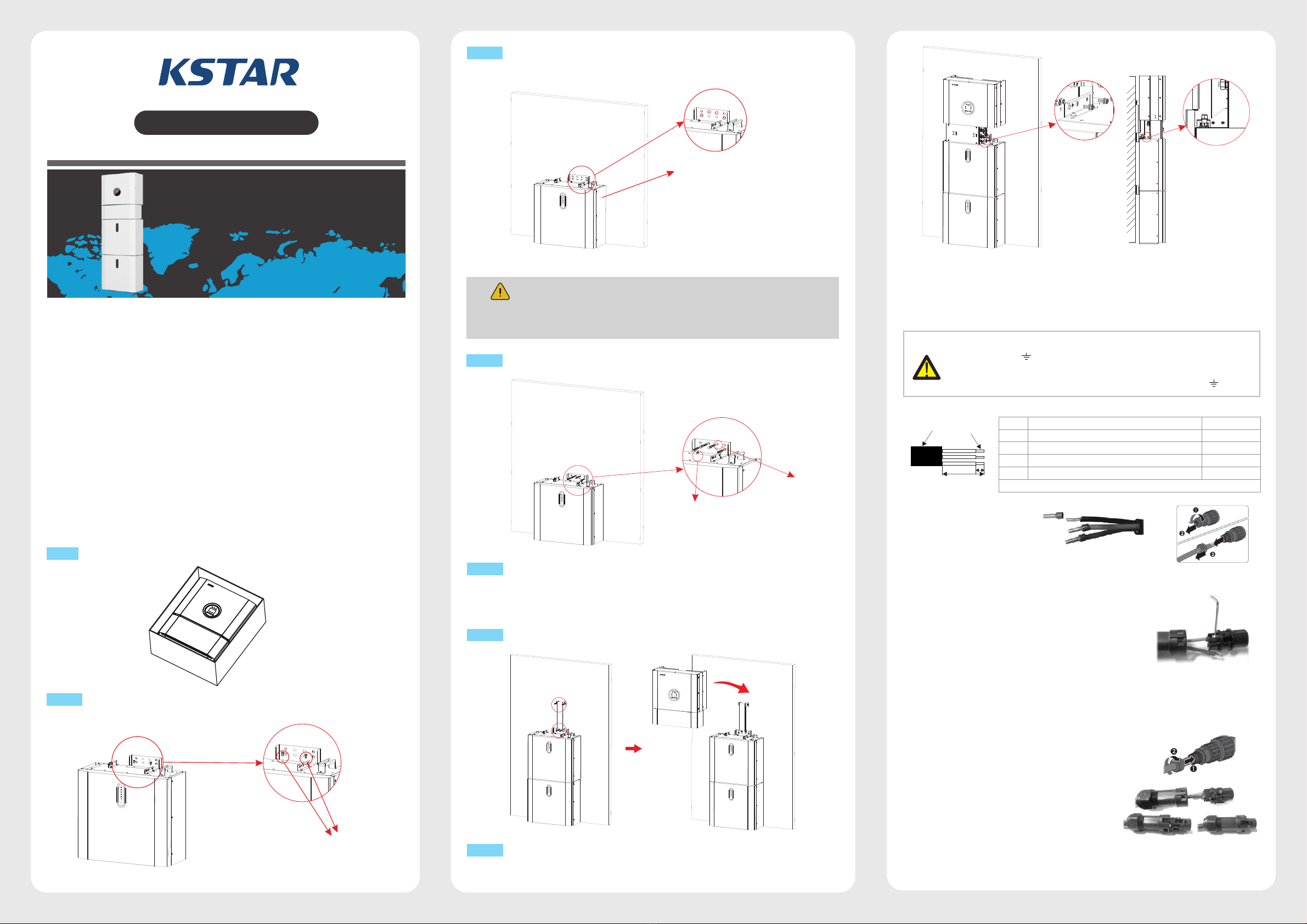
KSTAR BluE-H5/H3
ENERGY STORAGE SYSTEM
QuickInstallation
Step 1 Remove the battery and inverter from the packaging box.
Step 2 Assemble the battery mounting panel on the battery.
1. Battery Installation
Step 3 Position the battery parallel to the wall and use a Φ8mm drill to drill holes at a
depth of about 70mm in the wall for subsequent fixation of the mounting plates.
Step 4
Remove the debris baffle and secure the battery to the wall with screws and gaskets.
NOTE:
The type B RCD must be installed on the backup port of the system.In additon, the
installation of inverter must fulfill AS/NZS 3000,AS/NZS 4777.1 and AS/NZS 5033.
To assemble the second (and all other) battery, repeat steps 6 and 7,
respectively.
Step 5
BluE-Energy Storage System -
Quick Installation Guide
2.Inverter Installation
Inverter Installation.
Step 6
Hang the inverter onto the mounting panels, adjust the entire system and
ensure that the battery and the inverter have been securely hung onto the panels and
brackets.
Step 7
3.AC Cable Assembly and Connection
WARNING:
There are"L" "N'' '' '' symbols marked inside the connector, the Line wire of
grid must be connected to "L" terminal; the Neutral wire of grid must be
connected to "N" terminal; the Earth of grid must be connected to '' ''
Object Description Value
12mm to 18mm
4mm² to 10mm²
approx.13mm
approx.53mm
External diameter
Copper conductor cross-section
Stripping length of the insulated conductors
Stripping length of the outer sheath of the AC cable
A
B
C
D
The PE conductor must be 10mm longer than the L and N conductors
A
B
DC
U
O
W
For all AC connections, 4-10mm² 105 XJ cable is required to be used. Please make
sure the resistance of cable is lower than 1 ohm. If the wire is longer than 20m, it's
recommended to use 10mm² cable.
b. Insert the conductor into the
suitable ferrule acc. to DIN
46228-4 and crimp the contact.
c. Unscrew the swivel nut from the threaded sleeve and
thread the swivel nut and threaded sleeve over the AC cable.
d. Insert the crimped conductors L, N and PE into the
corresponding terminals and tighten the screw with a
hex key wrench screwdriver(size:2.5, 1.2-2.0Nm).
Ensure that all conductors are securely in place in the
screw terminals on the bush insert.
e. Screw the swivel nut onto the threaded sleeve. This seals the AC connector and provides
strain relief for the AC cable. When doing so, hold the bush insert firmly by the locking cap.
This ensures that the swivel nut can be screwed firmly onto the threaded sleeve.
d
e
f. Assembly the plug shell ,adapter as below
picture, Push the adapter and Shell by hand
until a “Click” is heard or felt.
f
g. Plug the AC connector into the jack for the
AC connection by hand until a “Click” is
heard or felt.
d
c
b
M5*12 Screws
Debris Baffle, drill φ8,
depth about 70 mm
ST6.3*50
Gasket


