manuals.online logo
Brands
  1. Home
  2. •
  3. Brands
  4. •
  5. KTM Power Parts
  6. •
  7. Motorcycle Accessories
  8. •
  9. KTM Power Parts 61412925020 User manual

KTM Power Parts 61412925020 User manual

3.213.522
61412925020
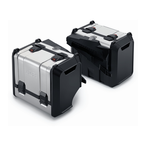
CYLINDER LOCK SET
06.2016
INFORMATION
KTM Sportmotorcycle GmbH
5230 Mattighofen, Austria
www.ktm.com
*3213522*
2
Le agradecemos que se haya decidido por este producto.
Este producto de alta calidad está probado para la competición y se ha desarrollado especíğcamente para las exigencias de este deporte. Para poder garantizar
los máximos niveles de seguridad y funcionalidad, es imprescindible que el producto se monte correctamente. Por este motivo, es muy importante que siga las
instrucciones del manual de montaje o que se ponga en contacto con su concesionario autorizado.
El (cuasi) fabricante y el proveedor de este producto no se harán responsables del montaje y el uso incorrectos.
¡Muchas gracias!
Wir freuen uns, dass Sie sich für dieses Produkt entschieden haben.
Unser hochwertiges Qualitätsprodukt ist rennerprobt und wurde speziell für sportliche Herausforderungen entwickelt. Eine korrekte Montage des Produktes
ist unerlässlich, um ein Maximum an Sicherheit und Funktionalität gewährleisten zu können. Bitte befolgen Sie daher die Montageanleitung oder wenden Sie
sich an Ihren autorisierten Fachhändler.
Für falsche Montage oder Verwendung dieses Produktes kann der (Quasi-)Hersteller bzw. Lieferant nicht zur Verantwortung gezogen werden.
Vielen Dank.
Thank you for choosing this product.
Our high quality product has been tested under racing conditions and was developed speciğcally for use in sports activities. Correct installation of the product
is essential to ensure that a maximum degree of safety and functionality is achieved. Therefore, please follow the installation instructions or contact your
authorized dealer.
The (quasi) manufacturer or supplier cannot be held responsible for products that are incorrectly mounted or inappropriately used.
Thank you.
Grazie per aver scelto questo prodotto.
Questo nostro prodotto di pregiata qualità è collaudato nelle competizioni ed è stato sviluppato speciğcamente per gare sportive. Il montaggio corretto del prodotto
è fondamentale per garantirne la massima sicurezza e funzionalità. Rispetti quindi le istruzioni di montaggio o rivolgersi al proprio concessionario autorizzato.
Il produttore (detentore del marchio)/fornitore non può essere considerato responsabile per un montaggio o impiego errato del presente prodotto.
Vi ringraziamo per l’attenzione!
Merci d‘avoir porté votre choix sur ce produit.
Notre produit de haute qualité est éprouvé pour les compétitions et a été conçu spécialement pour un usage sportif. Un montage approprié du produit est
indispensable pour garantir une sécurité et une fonctionnalité maximales du véhicule. C‘est pourquoi nous vous invitons à suivre scrupuleusement le manuel
de montage ou à vous adresser à votre revendeur agréé.
En cas de montage ou d‘utilisation non conformes de ce produit, le (quasi) constructeur ou le fournisseur déclinent toute responsabilité.
Merci !
17 ITALIANO
24 FRANÇAIS
31 ESPAÑOL
3 DEUTSCH
10 ENGLISH
3
DEUTSCH
- Schrauben mit Dichtring entfernen.
- Schlüsselstellung : Koffer abnehmbar bzw. montierbar
- Verriegelungseinheit aus der Führung entfernen.
HINWEIS
Auf Verbleib der Hebel und Federn achten.
- Schrauben (1 von Verriegelungseinheit entfernen.
- Deckel abnehmen.
Lieferumfang Schließzylinder (2x)
1x Schließzylinder 
12x Zuhaltung 
15x Feder für Zuhaltung 
2x Einrastblech 
1x Feder für Einrastblech 
1x O-Ring 
Der Kit enthält viele Kleinteile. Es wird empfohlen den Zusam-
menbau an einem Tisch sitzend durchzuführen!
Schlossausbau Kofferset 61412925000EB_BH
- Schlüsselstellung : Koffer abgeschlossen
In dieser Stellung lässt sich der Schlüssel abziehen.
- Schlüsselstellung : Koffer lässt sich öffnen
In dieser Stellung lässt sich der Schlüssel abziehen.
- Schlüsselstellung : Koffer abnehmbar bzw. montierbar
In dieser Stellung lässt sich der Schlüssel nicht abziehen.
4
DEUTSCH
- Bauteil (4 entfernen.
- O-Ring (Lieferumfang) montieren.
- Schließzylinder (Lieferumfang) wie in der Abbildung gezeigt posi-
tionieren und mit Hilfe des Schlüssels einsetzen (Nase muss nach
oben zeigen).
Einrastblech (3 rastet ein.
- Bauteil (4 montieren.
- Schlüsselstellung : Koffer abnehmbar bzw. montierbar
- Kappe (2 montieren.
- Verriegelungsplatte (5 nach links schieben.
- Kappe (2 entfernen.
- Schlüsselstellung : Koffer abgeschlossen
- Einrastblech (3 in den Schließzylinder hineindrücken.
- Schließzylinder entfernen.
Schlüssel muss unbedingt im Schließzylinder verbleiben!
5
- Schlüsselstellung : Koffer abgeschlossen
- Hebel und Federn montieren.
- Verriegelungseinheit in der Führung montieren.
HINWEIS
Auf richtigen Sitz der Hebel und Federn achten.
Die Verriegelungseinheit muss so montiert werden, dass sie
oben und unten bündig am Koffer ansteht!
- Schrauben (1 montieren und festziehen.
- Deckel montieren.
HINWEIS
Zunächst oben mit den Nasen einhaken und dann nach unten klap-
pen.
- Schrauben mit Dichtring montieren und festziehen.
DEUTSCH
6
Schlossausbau Top Case 42l 60312929000
- Schlüsselstellung : Koffer abgeschlossen
In dieser Stellung lässt sich der Schlüssel abziehen.
- Schlüsselstellung : Koffer lässt sich öffnen
In dieser Stellung lässt sich der Schlüssel abziehen.
- Schlüsselstellung : Koffer abnehmbar bzw. montierbar
In dieser Stellung lässt sich der Schlüssel nicht abziehen.
- Schlüsselstellung : Koffer lässt sich öffnen
- Schrauben entfernen.
- Schrauben entfernen.
- Schrauben entfernen.
- Schrauben (1 entfernen.
DEUTSCH
7
- Topcase in die dargestellte Position drehen.
- Aufgeklippte Blende abnehmen und Schrauben (2 entfernen.
- Schrauben (3 lösen.
- Verriegelungseinheit (4 entfernen.
- Schlüsselstellung : Koffer abnehmbar bzw. montierbar
- Bauteil (5 abnehmen.
- Bauteil (6 abnehmen.
DEUTSCH
8
- Einrastblech (7 in den Schließzylinder hineindrücken.
- Schließzylinder entfernen.
Schlüssel muss unbedingt im Schließzylinder verbleiben!
- Der Zusammenbau erfolgt in umgekehrter Reihenfolge.
Schlossausbau Touring Koffer 60312924100_25100
- Schlüsselstellung : Koffer abgeschlossen
In dieser Stellung lässt sich der Schlüssel abziehen.
- Schlüsselstellung : Koffer lässt sich öffnen
In dieser Stellung lässt sich der Schlüssel abziehen.
- Schlüsselstellung : Koffer abnehmbar bzw. montierbar
In dieser Stellung lässt sich der Schlüssel nicht abziehen.
- Schlüsselstellung : Koffer lässt sich öffnen
- Schrauben entfernen.
- Schrauben entfernen.
- Schraube entfernen.
DEUTSCH
9
- Koffer in die dargestellte Position drehen.
- Aufgeklippte Blende abnehmen und Schrauben (1 entfernen.
- Seitenteil (2 aufklappen.
- Verriegelungseinheit (3 entfernen.
- Schlüsselstellung : Koffer abnehmbar bzw. montierbar
- Bauteil (4 abnehmen.
- Bauteil (5 abnehmen.
- Einrastblech (6 in den Schließzylinder hineindrücken.
- Schließzylinder entfernen.
Schlüssel muss unbedingt im Schließzylinder verbleiben!
- Der Zusammenbau erfolgt in umgekehrter Reihenfolge.
DEUTSCH
10
ENGLISH
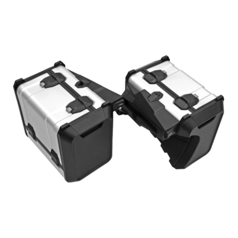
Locking cylinder (2x) included
1x locking cylinder 
12x wafers 
15x spring for wafer 
2x snap-in plates 
1x spring for snap-in plate 
1x O-ring 
This kit contains many small parts. It is advisable to carry out
assembly while sitting at a table!
Lock removal, Case Set 61412925000EB_BH
- Key position : The case is locked
The key can be pulled out in this position.
- Key position : The case can be opened
The key can be pulled out in this position.
- Key position : The case can be removed or mounted
The key cannot be pulled out in this position.
- Remove screws with seal ring .
- Key position : The case can be removed or mounted
- Remove lock unit from the guide.
NOTE
Ensure the lever and springs remain in place.
- Remove screws (1 from lock unit.
- Remove the cover.
11
- Remove plug (2.
- Key position : The case is locked
- Push snap-in plate (3 into the locking cylinder.
- Remove locking cylinder.
Key must remain in the locking cylinder!
- Remove component (4.
- Mount O-ring (included).
- Position locking cylinder (included) as shown in the figure and
insert with the aid of the key (catch must face upward).
Snap-in plate (3 engages.
- Mount component (4.
- Key position : The case can be removed or mounted
- Mount plug (2.
- Push locking plate (5 to the left.
ENGLISH
12
- Mount cover.
NOTE
First hook in at the top with the catches and then fold down.
- Mount and firmly tighten screws (1.
- Key position : The case is locked
- Mount lever and springs .
- Mount lock unit in the guide.
NOTE
Ensure the lever and springs are seated properly.
The locking unit must be mounted in such a way that it is flush
with the case at the top and the bottom!
- Mount screws with seal ring and tighten.
ENGLISH
13
Lock removal, Top Case 42l 60312929000
- Key position : The case is locked
The key can be pulled out in this position.
- Key position : The case can be opened
The key can be pulled out in this position.
- Key position : The case can be removed or mounted
The key cannot be pulled out in this position.
- Key position : The case can be opened
- Remove screws .
- Remove screws .
- Remove screws .
- Remove screws (1.
ENGLISH
14
- Rotate the top case into the position shown.
- Take off the unclipped cover panel and remove screws (2.
- Loosen screws (3.
- Remove locking unit (4.
- Key position : The case can be removed or mounted
- Take off component (5.
- Take off component (6.
ENGLISH
15
- Push snap-in plate (7 into the locking cylinder.
- Remove locking cylinder.
Key must remain in the locking cylinder!
- Reassemble in reverse order.
Lock removal, Touring Case 60312924100_25100
- Key position : The case is locked
The key can be pulled out in this position.
- Key position : The case can be opened
The key can be pulled out in this position.
- Key position : The case can be removed or mounted
The key cannot be pulled out in this position.
- Key position : The case can be opened
- Remove screws .
- Remove screws .
- Remove screw .
ENGLISH
16
- Rotate the case into the position shown.
- Take off the unclipped cover panel and remove screws (1.
- Open side part (2.
- Remove locking unit (3.
- Key position : The case can be removed or mounted
- Take off component (4.
- Take off component (5.
- Push snap-in plate (6 into the locking cylinder.
- Remove locking cylinder.
Key must remain in the locking cylinder!
- Reassemble in reverse order.
ENGLISH
17
Materiale fornito blocchetto serratura (2x)
N. 1 blocchetto serratura 
N. 12 meccanismi di ritenuta 
N. 15 molle per meccanismi di ritenuta 
N. 2 lamierini d’innesto 
N. 1 molla per lamierino d’innesto 
N. 1 O-ring 
Il kit contiene molta minuteria. Si consiglia di effettuare l’as-
semblaggio stando seduti a un tavolo!
Smontaggio della serratura set di borse
61412925000EB_BH
- Chiave in posizione : borsa chiusa a chiave
In questa posizione è possibile estrarre la chiave.
- Chiave in posizione : la borsa può essere aperta
In questa posizione è possibile estrarre la chiave.
- Chiave in posizione : la borsa può essere montata o tolta
In questa posizione non è possibile estrarre la chiave.
- Rimuovere le viti con l’anello di tenuta .
- Chiave in posizione : la borsa può essere montata o tolta
- Rimuovere l’unità di bloccaggio dalla guida.
AVVERTENZA
Verificare la posizione della leva e delle molle .
- Rimuovere le viti (1 dell’unità di bloccaggio.
- Rimuovere il coperchio.
ITALIANO
18
- Rimuovere il tappo (2.
- Chiave in posizione : borsa chiusa a chiave
- Spingere il lamierino d’innesto (3 nel blocchetto serratura.
- Rimuovere il blocchetto serratura.
La chiave deve assolutamente rimanere nel blocchetto serratura!
- Rimuovere il componente (4.
- Montare l’O-ring (in dotazione).
- Posizionare il blocchetto serratura (in dotazione) nel modo illustra-
to in figura e inserirlo con l’ausilio della chiave (il nasello deve
indicare verso l’alto).
Il lamierino d’innesto (3 si aggancia.
- Montare il componente (4.
- Chiave in posizione : la borsa può essere montata o tolta
- Montare il tappo (2.
- Spingere a sinistra la piastra di bloccaggio (5.
ITALIANO
19
- Montare il coperchio.
AVVERTENZA
Agganciare prima in alto con i naselli e quindi richiudere verso il
basso.
- Montare e serrare le viti (1.
- Chiave in posizione : borsa chiusa a chiave
- Montare la leva e le molle .
- Montare l’unità di bloccaggio nella guida.
AVVERTENZA
Verificare il corretto posizionamento della leva e delle molle .
L’unità di bloccaggio deve essere montata in modo tale da
essere a filo in alto e in basso con la borsa!
- Montare e serrare le viti con l’anello di tenuta .
ITALIANO
20
Smontaggio della serratura Top Case 42l 60312929000
- Chiave in posizione : borsa chiusa a chiave
In questa posizione è possibile estrarre la chiave.
- Chiave in posizione : la borsa può essere aperta
In questa posizione è possibile estrarre la chiave.
- Chiave in posizione : la borsa può essere montata o tolta
In questa posizione non è possibile estrarre la chiave.
- Chiave in posizione : la borsa può essere aperta
- Rimuovere le viti .
- Rimuovere le viti .
- Rimuovere le viti .
- Rimuovere le viti (1.
ITALIANO

Other manuals for 61412925020

1

Other KTM Power Parts Motorcycle Accessories manuals

KTM Power Parts 69005283000 Owner's manual

KTM Power Parts

KTM Power Parts 69005283000 Owner's manual

KTM Power Parts 78135941244 User manual

KTM Power Parts

KTM Power Parts 78135941244 User manual

KTM Power Parts 93012935044 Owner's manual

KTM Power Parts

KTM Power Parts 93012935044 Owner's manual

KTM Power Parts 60712912044 Owner's manual

KTM Power Parts

KTM Power Parts 60712912044 Owner's manual

KTM Power Parts 77735936144 User manual

KTM Power Parts

KTM Power Parts 77735936144 User manual

KTM Power Parts 60307940000 User manual

KTM Power Parts

KTM Power Parts 60307940000 User manual

KTM Power Parts 78001095000 User manual

KTM Power Parts

KTM Power Parts 78001095000 User manual

KTM Power Parts 61302931044 Owner's manual

KTM Power Parts

KTM Power Parts 61302931044 Owner's manual

KTM Power Parts 6201292700004 User manual

KTM Power Parts

KTM Power Parts 6201292700004 User manual

KTM Power Parts 54803190100 User manual

KTM Power Parts

KTM Power Parts 54803190100 User manual

KTM Power Parts 93008908044 Owner's manual

KTM Power Parts

KTM Power Parts 93008908044 Owner's manual

KTM Power Parts 90508915000 Owner's manual

KTM Power Parts

KTM Power Parts 90508915000 Owner's manual

KTM Power Parts 60303990044 Owner's manual

KTM Power Parts

KTM Power Parts 60303990044 Owner's manual

KTM Power Parts 90109945000 User manual

KTM Power Parts

KTM Power Parts 90109945000 User manual

KTM Power Parts 79612917000 User manual

KTM Power Parts

KTM Power Parts 79612917000 User manual

KTM Power Parts 69109945000 Owner's manual

KTM Power Parts

KTM Power Parts 69109945000 Owner's manual

KTM Power Parts 93008915044 Owner's manual

KTM Power Parts

KTM Power Parts 93008915044 Owner's manual

KTM Power Parts 60712929000 Owner's manual

KTM Power Parts

KTM Power Parts 60712929000 Owner's manual

KTM Power Parts 60812905044 User manual

KTM Power Parts

KTM Power Parts 60812905044 User manual

KTM Power Parts 61303946044 Owner's manual

KTM Power Parts

KTM Power Parts 61303946044 Owner's manual

KTM Power Parts 60112020000 User manual

KTM Power Parts

KTM Power Parts 60112020000 User manual

KTM Power Parts 60112024050 User manual

KTM Power Parts

KTM Power Parts 60112024050 User manual

KTM Power Parts 90805979044 Owner's manual

KTM Power Parts

KTM Power Parts 90805979044 Owner's manual

KTM Power Parts 69105283100 Owner's manual

KTM Power Parts

KTM Power Parts 69105283100 Owner's manual

Popular Motorcycle Accessories manuals by other brands

Sperian Optrel p430 User instructions

Sperian

Sperian Optrel p430 User instructions

KLOCK WERKS Flare Installation instruction

KLOCK WERKS

KLOCK WERKS Flare Installation instruction

Sena MOMENTUM INC PRO quick start guide

Sena

Sena MOMENTUM INC PRO quick start guide

R&G FI0134BK Fitting instructions

R&G

R&G FI0134BK Fitting instructions

KFI 101320 installation instructions

KFI

KFI 101320 installation instructions

Shark VARIAL RS Safety and instructions for use

Shark

Shark VARIAL RS Safety and instructions for use

probrake TR12-1 Mounting instruction

probrake

probrake TR12-1 Mounting instruction

TERMOSCUD R244 PRO instruction manual

TERMOSCUD

TERMOSCUD R244 PRO instruction manual

Memphis Shades 2321-0060 Mounting instructions

Memphis Shades

Memphis Shades 2321-0060 Mounting instructions

hepco & becker 5019518 00 01 quick start guide

hepco & becker

hepco & becker 5019518 00 01 quick start guide

BRUUDT CBR1000RR Mounting instructions

BRUUDT

BRUUDT CBR1000RR Mounting instructions

Menuett 014420 operating instructions

Menuett

Menuett 014420 operating instructions

R&G SP0085BK Fitting instructions

R&G

R&G SP0085BK Fitting instructions

LSL 150H131 FITTING INSTRUCTION

LSL

LSL 150H131 FITTING INSTRUCTION

Xenith EPIC Player's manual

Xenith

Xenith EPIC Player's manual

warmer TYD193-137-2D6C Series User instruction

warmer

warmer TYD193-137-2D6C Series User instruction

Piaa 1100p Series installation instructions

Piaa

Piaa 1100p Series installation instructions

hepco & becker 501201 00 02 quick start guide

hepco & becker

hepco & becker 501201 00 02 quick start guide

manuals.online logo
manuals.online logoBrands
  • About & Mission
  • Contact us
  • Privacy Policy
  • Terms and Conditions

Copyright 2025 Manuals.Online. All Rights Reserved.