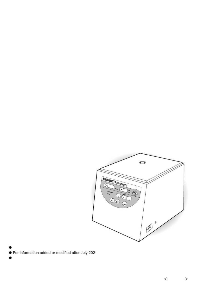
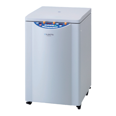
Kubota 2420 User manual

KUBOTA CORPORATION
29-9 HONGO 3-CHOME
,
BUNKYO-KU
,
TOKYO 1 13- 0033
,
JA PA N
To ensure
p
ro
p
er o
p
eration of the centrifu
g
e, be sure to read this manual
carefull
y
before o
p
eratin
g
it.
Also
,
kee
p
this manual hand
y
so that
y
ou can refer to it at an
y
time.
■The
p
roducts bein
g
indicated in this Instruction manual are desi
g
ned f or o
p
era-
tors carr
y
in
g
ex
p
ert knowled
g
e and these
p
roducts are to be used b
y
these
q
u-
alified o
p
erators observin
g
the indicated
p
recautions for res
p
ective
p
ur
p
oses.
For
p
ersons lackin
g
necessar
y
ex
p
ert knowled
g
e
,
these
p
rodu ces ma
y
be diffi-
cult to use
p
ro
p
erl
y
andevendan
g
er ma
y
be conse
q
uent u
p
on the use.
When the aforesaid
p
ersons lackin
g
the necessar
y
ex
p
ert knowled
g
eareusin
g
these
p
roducts
,
do so under a
p
p
ro
p
riate su
p
ervision and
g
uidance of the
q
uali-
fied o
p
erators
p
ossessin
g
the necessar
y
ex
p
ert knowled
g
e.
NOTE
INSTRUCTION
and
SERVICE MANUAL
[
4
0
P
a
g
e
s
]
F30241106
■D
o
n
o
t
d
i
s
t
ri
b
u
t
e
t
hi
s
m
a
n
u
a
lwi
t
hin
t
h
e
U
.
S
.A.
,
M
e
xi
c
o
,
C
a
n
a
d
a
a
n
d
A
u
s
t
r
a
li
a
as the Products advertised in the manual shall not be distributed in the U. S.A.
,
Mexico
,
Canada and Australia.
TABLE-TOP CENTRIFUGE
Ma
y
2005
,
PrintedinJa
p
an
For infor ma ti on added or modified after June 2005
,
p
lease contact
y
our local dealer.

WARRANTY
Kubota Cor
p
oration
(
"Kubota"
)
warrants that the instrument covered b
y
this warrant
y
shall be
free from defects in material and workmanshi
p
under normal use. Kubota will re
p
air or re
p
lace
,
free of all char
g
es
,
the instrument which
,
within one
(
1
)
y
ear after deliver
y
or fifteen
(
15
)
months
after shi
pp
in
g,
whichever comes earlier is
p
roved to the satisfaction of Kubota to have been
defective at the time of deliver
y,
p
rovided that it does not fall under the exce
p
tions and conditions
s
p
ecified in this warrant
y
. Such exce
p
tion and conditions include
,
but are not limited to
,
failure
due to natural wear and tear
,
accident
,
ne
g
li
g
ence
,
alteration
,
re
p
air
,
or o
p
eration in a manner not
p
rescribed in the Instruction Manual su
pp
lied with the instrument. The fore
g
oin
g
ex
p
resses
Kubotas sole warrant
y
with res
p
ect to the instrument.
THIS WARRANTY IS MADE IN LIEU OF ANY AND ALL OTHER WARRANTIES AND ALL
IMPLIED WARRANTIES OF MERCHANTABILITY AND FITNESS FOR A PARTICULAR
PURPOSE ARE HEREBY DISCLAIMED AND EXCLUDED.
Kubota and its authorized dealers will not be liable for an
y
conse
q
uential dama
g
es
,
loss or
ex
p
ense arisin
g
from the im
p
ro
p
er use of the instrument. Kubota will not honor an
y
other
warrant
y,
which ma
y
be
g
iven
,
b
y
its re
p
resentative or dealer or otherwise which is different from
the warrant
y
g
iven hereunder. This warrant
y
is not assi
g
nable and is o
p
erative onl
y
in favor of the
ori
g
inal customer to whom this warrant
y
is ori
g
inall
y
delivered.
Use of Model 2420
Model 2420 can be used for
p
re
p
rocessin
g
in in-vitro anal
y
sis
,
which breaks down blood or urine
sam
p
les containin
g
p
lasmas or cells. Accordin
g
l
y
, it is not desi
g
ned to connect directl
y
to a
p
atient's bod
y
.
Do not use the centrifu
g
e for se
p
aration of an
y
hazardous material
(
ex
p
losive
,
chemicall
y
active
,
or
g
anic
,
or radiation containin
g
material
,
or material contaminated b
y
p
atho
g
enic microor
g
anisms
)
or oil.
Co
py
ri
g
ht
C
1995 KUBOTA Manufacturin
g
Cor
p
orati on

■“Serious in
j
ur
y
"is defined as in
j
uries such as loss of e
y
esi
g
ht, burn
(
hi
g
h / low tem
p
erature
)
,
electric shock
,
fracture of bone
,
p
oisonin
g
causin
g
aftereffects
,
or an
y
ot her in
j
uries re
q
uirin
g
a
lon
g
-term medical treatment at hos
p
ital.
■“Non-fatal in
j
ur
y
" is defined as burns, electric shock, or an
y
other in
j
uries which does not
re
q
uire lon
g
-term medical treatment at hos
p
ital. "Pro
p
ert
y
dama
g
e" is defined as ex
p
ansion
dama
g
e related to dama
g
e to e
q
ui
p
ment or other
p
ro
p
erties.
Safety Instructions
The centrifu
g
e and the manual indicate im
p
ortant information in order to ensure safe
o
p
eration of the centrifu
g
e and to
p
revent
p
h
y
sical in
j
uries and
p
ro
p
ert
y
dama
g
es.
B
e
su
r
e
to
u
n
de
r
st a
n
d
t
h
e
m
ea
nin
gs
o
f
t
h
e
f
o
ll
o
win
g
in
d
i
cat
i
o
n
s
a
n
d
f
o
ll
o
w
t
h
e
instructions.
2. Ex
p
lanation of
p
ictorial marks
1. Ex
p
lanation of indication marks
WARNING
CAUTION
Indication Meanin
g
It is a
p
ossibilit
y
of serious accident resultin
g
in
death or serious in
j
ur
y
.
It is a
p
ossibilit
y
of accident resultin
g
in sli
g
ht or
non-fatal in
j
ur
y
or
p
ro
p
ert
y
dama
g
e.
Pictorial marks Meanin
g
Indi cate s
p
rohibition
(
thin
g
s
y
ou must not do
)
.
Details are shown near the mark
,
usin
g
illustration or
sentences.
Indi cate s c om
p
ulsion
(
thin
g
s
y
ou have to do
)
.
Details are shown near the mark
,
usin
g
illustration or
sentences.
Indicates caution
,
warnin
g
and dan
g
er.
Details are shown near the mark
,
usin
g
illustration or
sentences.
This label indicates the risk of electric shock.
Touchin
g
this attached
p
art will cause an electric shock.
This label indicates a hot section.
Touchin
g
this attached
p
art will cause an burn.
Indicates that the
p
ower is on.
It is indicated on the
p
ower switch and the circuit breaker.
Indicates that the
p
ower is off.
It is indicated on the
p
ower switch and the circuit breaker.

p
a
g
e
Safet
y
Instructions
General Notes・・・・・・・・・・・・・・・・・・・・・・Ⅰ
Usabl e Rotor ・・・・・・・・・・・・・・・・・・・・・・・Ⅳ
Lifetime of rotors・・・・・・・・・・・・・・・・・・・Ⅳ
Number of times allowed for
autoclavin
g
of rotor・・・・・・・・・・・・・・・・Ⅴ
Section 1.
Com
p
onent Name and Ex
p
lanation
1-1.Appear ance・・・・・・・・・・・・・・・・・・・・・ 1-1
1-2.Control Panel ・・・・・・・・・・・・・・・・・・・ 1-2
Section 2.
Installation and Power Su
pp
l
y
2-1.Unpacking・・・・・・・・・・・・・・・・・・・・・・ 2-1
2-2.Place of Installation ・・・・・・・・・・・・・・ 2-1
2-3.Movement of centrifu
g
e・・・・・・・・・・・ 2-1
2-4.Power Re
q
uirement
・・・・・・・・・・・・・・・ 2-2
2-5.Groundin
g
・・・・・・・・・・・・・・・・・・・・・・ 2-3
Section 3. O
p
eration
3-1.Cautions of O
p
eration・・・・・・・・・・・・・ 3-1
3-2.O
p
eration ・・・・・・・・・・・・・・・・・・・・・ 3-1
3-3.O
p
enin
g
and Closin
g
the lid・・・・・・・・ 3-4
[1] Turnin
g
on the
p
ower and o
p
enin
g
the lid
・・・・・・・・・・・・・・・・・・・・・・・・・ 3-4
[2] Opening the lid during power failure・3-4
[3] Closing the lid・・・・・・・・・・・・・・・・・・ 3-5
3-4.Setting the Speed・・・・・・・・・・・・・・・・・ 3-6
[1] Setting the speed by the rpm・・・・・・・ 3-6
[2] Setting the speed by the centrifugal
force( ×g)・・・・・・・・・・・・・・・・・・・・ 3-7
page
3-5.Settin
g
the Timer
・・・・・・・・・・・・・・・・3- 8
3-6.Settin
g
the acce leration ・deceleration
・・・・・・・・・・・・・・・・・・・・・・・・・・・・・・ 3- 9
3-7.Savin
g
the Memor
y
・・・・・・・・・・・・・・3-10
[1] Savin
g
the Memor
y
・・・・・・・・・・・・・3-10
[2] Memor
y
cancellation
・・・・・・・・・・・・ 3-10
3-8.Settin
g
the Function ・・・・・・・・・・・・・ 3-11
[1] Settin
g
the Rotation Radius・・・・・・・ 3-12
[2] Settin
g
the “SLOW" deceleration
・・・・・・・・・・・・・・・・・・・・・・・・・・・・・ 3-13
[3] Setting the Sound that informs
the end of the operation・・・・・・・・・・3-14
[4] Reverse of setting order of
the Speed and the Timer ・・・・・・・3-15
[5] Setting the Reminder alarm・・・・・・・3-16
[6] Setting the Indicators for
the end of the operation ・・・・・・・3-17
3-9.Calculating Centrifugal Force・・・・・・ 3-18
3- 10.
Allow able lo ad and
Reduced maximum s
p
eed ・・・・・・3-18
Section 4. Service
4- 1.Dail
y
Ins
p
ection
・・・・・・・・・・・・・・・・・4-1
4- 2.Monthl
y
In s
p
ections ・・・・・・・・・・・・・4-2
4- 3.Annual Ins
p
ection・・・・・・・・・・・・・・・4-2
4- 4.Cleanin
g
and Sterilization・・・・・・・・・4-3
[1] Cleanin
g
the chambe r interior ・・・・・・ 4-3
[2] Cleanin
g
the rotor
,
buckets and
tube rack ・・・・・・・・・・・・・・・・・・・・・・ 4-4
[3] Sterilization of rotor, buckets and
tube rack ・・・・・・・・・・・・・・・・・・・・・・ 4-4
4- 5.Greasing・・・・・・・・・・・・・・・・・・・・・・・4-5
4- 6.Inspection of Circuit Protector ・・・・・4-6
4- 7.Using the Photoelectric Tachometer Port
・・・・・・・・・・・・・・・・・・・・・・・・・・・・・・ 4-7
Table of Contents

4- 8.Spare Parts Supply・・・・・・・・・・・・・・4- 8
4- 9.Manufacturer re
q
uirements at Re
p
air
or Maintenance
・・・・・・・・・・・・・・・・4- 8
4- 10.
Product Pre
p
aration When Returnin
g
Units for Re
p
air or for Other Reasons
・・・・・・・・・・・・・・・・・・・・・・・・・・・・・ 4- 9
Contaminant Elimination Certificate
・・・・・・・・・・・・・・・・・・・・・・・・・・・・ 4-10
Section 5. Troubleshootin
g
5-1.Alarm Indicators・・・・・・・・・・・・・・・・・ 5-1
E0・・・・・・・・・・・・・・・・・・・・・・・・・・・・ 5-1
C1・・・・・・・・・・・・・・・・・・・・・・・・・・・・ 5-2
C2・・・・・・・・・・・・・・・・・・・・・・・・・・・・ 5-2
C3・・・・・・・・・・・・・・・・・・・・・・・・・・・・ 5-2
C4・・・・・・・・・・・・・・・・・・・・・・・・・・・・ 5-2
C5・・・・・・・・・・・・・・・・・・・・・・・・・・・・ 5-2
5-2.Error Indicators・・・・・・・・・・・・・・・・・・ 5-3
E1・・・・・・・・・・・・・・・・・・・・・・・・・・・・ 5-3
E2・・・・・・・・・・・・・・・・・・・・・・・・・・・・ 5-3
E3・・・・・・・・・・・・・・・・・・・・・・・・・・・・ 5-3
E4・・・・・・・・・・・・・・・・・・・・・・・・・・・・ 5-4
E6・・・・・・・・・・・・・・・・・・・・・・・・・・・・ 5-4
E7・・・・・・・・・・・・・・・・・・・・・・・・・・・・ 5-4
5-3. Troubleshooting・・・・・・・・・・・・・・・・・ 5-5
Section 6. Rotor
6-1. Mountin
g
RS-240 Rotor
・・・・・・・・・・6- 1
6-2. Mountin
g
RS-1004 Rotor
・・・・・・・・・ 6- 2
6-3. Mountin
g
RMP-23 Rotor
・・・・・・・・・ 6- 3
6-4. RS-240 Swin
g
in
g
Buc ket Rotor・・・・6- 4
[1] S
p
ec if ic at ion ・・・・・・・・・・・・・・・・・・6- 4
[2] Settin
g
Bu ckets ・・・・・・・・・・・・・・・・6- 6
[3] Tube distribution method
・・・・・・・・・ 6- 6
[4] Cushions / Ada
p
ter ・・・・・・・・・・・・・6- 7
6-5. RS-1004 Swin
g
in
g
Buc ket Rotor・・・6-10
[1] S
p
ec if ic at ion ・・・・・・・・・・・・・・・・・・6-10
[2] Setting Bu ckets ・・・・・・・・・・・・・・・・6-11
[3] Tube distribution method・・・・・・・・・6-11
[4] Standard accessories・・・・・・・・・・・・6-11
6-6. RMP-23 Swingin g Bucket Rotor・・・6-12
[1] S
p
ec if ic at ion ・・・・・・・・・・・・・・・・・・ 6-12
[2] Check the trunnion
p
in
・・・・・・・・・・・ 6-13
[3] Settin
g
Buckets ・・・・・・・・・・・・・・・・6-13
[4] Distribution of sam
p
les・・・・・・・・・・6-14
[5] Settin
g
p
late・・・・・・・・・・・・・・・・・・・ 6-14
[6] Allowable wei
g
ht of
p
late ・・・・・・・・6-15
[7] Standard accessories・・・・・・・・・・・・ 6-15
Section 7. S
p
ecifications
7-1.Centrifu
g
e・・・・・・・・・・・・・・・・・・・・・・7-1
7-2.Sta ndard Acce ssories ・・・・・・・・・・・・・7-1
Section 8. Parts List
8-1.Recommended Spare Parts・・・・・・・・・8-1

Ⅰ
Do not
p
er for m dr
y
-heat or auto-
clave sterilization with tem
p
era-
tures hi
g
her t han those s
p
ecifi ed.
O
t
h
e
rwi
s
e
,
t
h
e
r
o
t
o
rm
a
y
d
e
t
e
ri
o
-
rate and cause an acci dent .
(2)Maximum s
p
eed
(4)Hazardous material
General Notes
Since lar
g
e electrical and mechanical ener
g
ies are
p
resent on the centrifu
g
eandrotor
,
reasonable care is re
q
uired for their handlin
g
.
Otherwise
,
failure ma
y
occur resultin
g
in
p
ro
p
ert
y
dama
g
es or fatal
p
h
y
sical in
j
uries.
In order to
p
revent them from ha
p
p
enin
g
,
be sure to follow the instruction
g
iven below.
Be sure to follow them.
(1)Maxi mum l oad
WARNING
(5)While the centrifu
g
eisino
p
er ati on
(6)Lid
Do not exceed the maximum load
of rotor and bucket.
The rotor or bucket used be
y
ond
the allowable load level can be
d
a
m
a
g
e
d
,
t
h
e
r
e
b
y
c
a
u
s
in
g
a
n
a
c
-
cident.
Kee
p
the rotor and bucket s
p
eed
below the maximum s
p
eed.
Excessive s
p
eed ma
y
cause dam-
a
g
etotherotor
,
bucket and the
centrifu
g
e. The max imum s
p
eed
de
p
ends on the rotor and bucket
stren
g
th.
Do not modif
y
,
nor use uns
p
eci-
fied
p
arts.
U
n
a
u
t
h
o
riz
e
d
r
e
t
r
o
fi
t
o
f
t
h
e
c
e
n
t
ri-
fu
g
e
,
rotororbucket
,
or use of un-
authorized
p
arts for them can re-
sult in accidents.
Whilethe centrifu
g
eisino
p
eration
,
do not stand closer than 30 cm to
avoid asecondar
y
ac cident.
Do not o
p
en the lid when the rotor
is s
p
innin
g
.
Ph
y
sical contact with the s
p
innin
g
rotor or bucket ma
y
cause serious
in
j
ur
y
.
(9)D
a
m
a
g
e
d
,
c
o
rr
o
d
e
d
,
rusted or def or med
(8)Rotor and drive shaft durin
g
rotation
Do not touch r otor and dri ve shaft
durin
g
the rotation.
Ph
y
sical contact with the s
p
innin
g
rotor or drive s haft ma
y
cause
serious i n
j
ur
y
.
Di
s
c
o
n
t
in
u
e
u
s
e
o
f
t
h
e
e
q
u
i
p
m
e
n
t
when its rotor or the buckets
found to have been dama
g
ed
,
corroded
,
rusted or def or med.
Otherwise failure ma
y
oc cur.
(7)Sterilization
Do not
p
ut an
y
hazardous mat er i-
al
(
ex
p
losive
,
chemicall
y
active
,
or
g
anic
,
or radiation containin
g
material
,
or ma ter ial c on taminated
b
y
p
atho
g
enic microor
g
anisms
)
as
asam
p
le of the centrifu
g
e and do
n
o
t
p
l
a
c
e
i
t
c
l
o
s
e
r
t
h
a
n
3
0
c
m
t
o
avoid a secondar
y
accident
s
h
o
u
l
d
t
h
e
c
e
n
t
rif
u
g
e
a
c
c
i
d
e
n
t
a
ll
y
rotate and contact the material.
(3)Modification
a
n
d
u
n
s
p
e
c
ifi
e
d
p
a
r
t
s

G
r
o
u
n
d
in
g
Installation
WARNING
Do not connect the
g
round cable
to the followin
g
p
laces:
1. Gas
p
i
p
in
g
Ex
p
losion or fire ma
y
occur.
2. Ground cable of li
g
htnin
g
Conduc tor
,
or tele
p
hone cable.
El ect r ic sho ck ma
y
occur in the
case of li
g
htenin
g
.
A clearance of 30 cm minimum
must be
p
rovided around the cen-
tr ifu
g
e.
If the centrifu
g
eisdrivenintoun-
c
o
n
t
r
o
ll
e
d
r
o
t
a
t
i
o
n
s
d
u
e
t
o
a
f
a
il-
ur e
,
secondar
y
dama
g
ecanresult
from ener
g
y
ab sor bed b
y
the rota-
ti on.
Do not install the centrifu
g
eonan
inclined
,
sli
p
p
er
y
,
or unstable sur-
f
a
c
e
.
Violent vibration ma
y
occur.
Ensure that the
g
round cable is
connected to the
g
roundin
g
termi-
n
a
l.
This
p
recaution must be strictl
y
observed to avoid accidents due
to electric shocks or leaka
g
e.
Installation
CAUTION
3. Water
p
i
p
es
Do not install the centrifu
g
eina
p
lace
wi
t
hhi
g
hh
u
mi
d
i
t
y
(
r
e
l
a
t
iv
e
h
u
mi
d
i
t
y
8
5
%
or above
)
.
L
e
a
k
o
r
a
c
c
i
d
e
n
t
m
a
y
o
c
c
u
r.
Do not install the centrifu
g
eina
p
lace
with
p
oor ventilation.
Otherwise inside tem
p
erature of the cen-
trifu
g
ema
y
rise
,
resultin
g
in accidents.
D
o
n
o
t
in
s
t
a
ll
t
h
e
c
e
n
t
rif
u
g
e
in
a
d
u
s
t
y
p
lace.
Do not install the centrifu
g
eina
p
lace where the tem
p
erature is
below 10 or over 40 .
A
p
l
a
c
e
wi
t
h
t
h
e
a
m
b
i
e
n
t
t
e
m
p
e
r
a
-
ture be
y
ond 40 can introduce
u
n
d
e
s
ir
a
b
l
e
b
u
il
d
-
u
p
o
fh
e
a
t
in
s
i
d
e
the centrifu
g
e and a
p
lace under
10 can cause the centrifu
g
e
malfunction and
,
as the r esult
,
ac-
cidents.
Lifetime of rotors
Use of rotors be
y
ond the lifetime
ma
y
lead to breaka
g
e of the rotor.
If the rotor is used continuousl
y
even after the lifetime of the rotor
has ex
p
ired
,
should the rotor
g
et
dama
g
ed an accident ma
y
occur.
Cit
y
water
p
i
p
es ma
y
not be
ade
q
uate as a
g
round since it
ma
y
consist of
p
lastic
p
i
p
in
g
.

CAUTION
F
a
s
t
e
n
a
r
o
t
o
r
Toxic or radioactive substances etc.
Bucket
T
u
b
e
r
a
c
k
)
Cushion
Cleanin
g
Caution
p
late
Wh
e
n
c
e
n
t
rif
u
g
in
g
o
f
s
u
b
s
t
a
n-
ces c ontaminated wi th
p
atho-
g
enic bacteria
,
or toxic or radio-
active substances
,
al wa
y
suse
containers that are
p
atho
g
enic
bacteria
,
toxic substance or ra-
di ation
p
roof.
O
t
h
e
rwi
s
e
,
inf
e
c
t
i
o
n
s
,
in
t
o
xi
c
a
-
tion or radioactive ex
p
osure ac-
c
i
d
e
n
t
s
m
a
y
o
c
c
u
r.
Do not use deter
g
ents exceed-
in
g
the ran
g
eof
p
H5-8orchlor-
ine deter
g
ents for washin
g
p
ur-
p
oses.
Corrosion ma
y
dama
g
etherotor
and bucket resultin
g
in dama
g
e
to the centrifu
g
e.
R
e
p
l
a
c
e
t
h
e
c
u
s
hi
o
nwh
e
n
t
h
e
g
lass or
p
lastic tube is cracked.
If the cushion with
g
lass fra
g
-
mentcuttoitisused
,
the tube is
easil
y
cracked.
Kee
p
the load
(
of the sam
p
le
,
bucket
,
etc.
)
balanced.
If an a
p
p
ro
p
riate balance is not
p
rovided
,
unex
p
ected accidents
can r esu lt fr om a dama
g
ed r otor
or centrifu
g
e.
Use the same t
y
p
e of tube racks.
The wron
g
arran
g
ement will
cause imbalance and resultin
g
in
dama
g
etorotor
,
bucket or the
centrifu
g
e.
Ensure that the rotor is firml
y
fastened to the drive shaft.
If not
p
ositivel
y
held in
p
lace
,
the rotor or centrifu
g
ecanbe
dama
g
ed
,
thereb
y
causin
g
acc i-
dents.
Thesamet
y
p
e buckets must be
p
rovidedtoever
y
rotor
y
oke.
If not
p
ositivel
y
held in
p
lace
,
the
rotororcentrifu
g
e can be dam-
a
g
ed
,
thereb
y
causin
g
accidents.
Do not remove the caution
p
lates.
When a caution
p
late becomes
di rt
y
,
blurred or
p
eeled off
,
re-
p
lace it with a new one
(
caution
p
lates are available at char
g
e
)
.
Balance of sam
p
le

Ⅳ
Use of rotors be
y
ond the lifetime ma
y
lead to breaka
g
e of the rotor.
If the rotor is used continuousl
y
even after the lifetime of rotors has ex
p
ired
,
should
the rotor
g
et dama
g
ed
,
the main unit of the centrifu
g
e suddenl
y
ma
y
start to rotate
;
this could result in an accident causin
g
in
j
ur
y
or death.
WARNING
Usable Rotor
Lifetime of rotors
Lifetime of rotors is 7
y
ears after the deliver
y
.
When 7
y
ears have
p
assed after the deliver
y,
discontinue o
p
eration of the centrifu
g
e to re
p
lace the
rotor with a new one.
Earlier re
p
lacement
,
however
,
is re
q
uired if an
y
corrosion
,
lowered stren
g
th
,
flaw or deform due to
incorrect o
p
eration is detected on the rotor.
In such case, contact
y
our local dealer and be sure to have the rotor checked before reusin
g
it.
WARNING
(1) Do not use an
y
rotors other than those s
p
ecified in
(
2
)
below.
If rotors other than those s
p
ecified are used
,
the rotors ma
y
be broken
,
resultin
g
in
a serious accident.
(2) The rotors that can mount as of Ma
y
2005 are as follows:
This information is sub
j
ect to addition or chan
g
e.
For information after June 2005
,
p
lease contact
y
our local dealer.
Swin
g
in
g
Bucket Rotor Plate Rotor
RS-240
RS-1004 RMP-23

Sto
p
the use of the rotor immediatel
y
when it is used be
y
ond the number of
times allowed for autoclavin
g
. Otherwise
,
the rotor ma
y
deteriorate b
y
the heat
g
enerated b
y
autoclavin
g,
res ultin
g
in deformation or destruction.
Should the rotor
g
et dama
g
ed, the main unit of the centrifu
g
e suddenl
y
ma
y
start to rotate
;
this could result in an accident causin
g
in
j
ur
y
or death.
WARNING
Ⅴ
Number of times allowed for autoclavin
g
of rotor
The number of times allowed for autoclavin
g
of each rotor should be deemed as follows.
When the followin
g
conditions has been met, discontinue o
p
eration of the centrifu
g
e to
re
p
lace the rotor with a new
p
art.
Earlier re
p
lacement
,
however
,
is re
q
uired if an
y
corrosion
,
lowered stren
g
th
,
flaw or deform
due to wron
g
o
p
eration is detected on the rotor. In such case
,
contact
y
our local dealer and
be sure to have the rotor checked before reusin
g
it.
[1] Number of times allowed for autoclavin
g
and tem
p
erature of rotor
[
2
]
Recordin
g
autoclave
After each autoclave
p
ro ces s
,
be sure to record the followin
g
(1)
to (3)
to control how
man
y
times the autoclave is executed.
(1)Date
(2)Tem
p
erature of autoclave
(3)Time of autoclave
You can take advanta
g
e of usin
g
the “Autoclave record table”
attached to
the rotor instruction manual.
Rotor Tem
p
erature of autoclave Number of times
allowed for autoclavin
g
RMP-23 121 ℃50 times
RS-1004 121 ℃100 times

ST
ART
ST
OP
TIME
min
sec
SP
EE
D
100rp m
100g
MEM
OR
Y
123
ACC
DE
C
F
UN
C
TIO N
1-1
“POWER"switch
Drive Shaft
Control
p
anel
Chamber
Front cover
Hook
Refer to Pa
g
e 1-2.
Refer to Pa
g
e 3-5.
Refer to Pa
g
e 3-4.
The lid o
p
ens whe n it is
p
ushed durin
g
the o
p
eration
sto
p
with the
p
ower on.
Lid
Tachometer
p
ort
Refer to Pa
g
e 4-7.
“OPEN
”
button
Refer to Pa
g
e 3-4.
Lid extreme release ca
p
Bucket intervention
p
revention
p
late
This
p
late
p
revents the touch of
the b ucket.
Do not remove this
p
la te
,
when
y
ou remove the rotor.
Section 1 Com
p
onent Name and Ex
p
lanation
1-1.A
pp
earance

1-2
1-2. Control Panel
Section1 Com
p
onent Name and Ex
p
lanation
START
STOP
TIME
min
sec
SPEED
100rpm
100g
MEMORY
123
ACC
DEC
FUNCTION
When this ke
y
is
p
ressed
the o
p
eration will b
e
started.
“START" ke
y
“TIME" dis
p
la
y
“STOP"ke
y
Press this key to
discontinue o
p
eration.
“ACC / DEC" ke
y
“FUNCTION" ke
y
This ke
y
allow the selection
of saved programs.
Pre ssin
g
the ke
y
will li
g
ht
the lamp.
MEMORY selection ke
y
“SPEED" dis
p
la
y
“SPEED/TIME"knob
Refer to Pa
g
e 3-10.
Refer to Pa
g
e 3-2.
(
Settin
g
the s
p
eed
,
RCF and time.
)
Refer to Pa
g
e 3-9. Refer to Pa
g
e 3-2.
(
To chan
g
e for ACC and DEC.
)
Refer to Pa
g
e 3-6.
(
To chan
g
e for s
p
eed /
RCF and time.
)
(
S
p
eed / R CF
)

2-1
Co
n
td
.
o
n n
e
x
t
page
.
●Never move the centrifu
g
e while the rotor is rotatin
g
or while the rotor is
attached to the centrifu
g
e. Otherwise
,
the drive shaft ma
y
become bent
or the rotor and the bucket ma
y
co me o ff
,
re sul tin
g
in an accident or
dama
g
e to the centrifu
g
e.
●Ensure that rotor and bucket are removed from the centrifu
g
e and that
the
p
ower cord is disconnected from the wall socket.
●Movin
g
the
p
osition of the centrifu
g
e while the
p
ower is turned on ma
y
cause electrification accident or functional failure of the centrifu
g
e.
WARNING
When installin
g
this centrifu
g
e, kee
p
3meters or more awa
y
from AM radio.
Noise
g
enerated b
y
this centrifu
g
e causes the sound of AM radio deteriorated.
A clearance of 30 cm minimum must be
p
rovided around the centrifu
g
e.
If the centrifu
g
e is driven into uncontrolled rotations due to a failure
,
secondar
y
dama
g
e can result from ener
gy
absorbed b
y
the rotation.
WARNING
Do not install the centrifu
g
e on an inclined, sli
pp
er
y
, or unstable surface.
Violent vibration ma
y
occur.
CAUTION
Section 2 Installation and Power Su
pp
l
y
2-1. Un
p
ackin
g
When the centrifu
g
e is taken out of a corru
g
ated carton box, check the followin
g
.
(1)
U
p
on receivin
g
the centri fu
g
e, examine it for an
y
visible dama
g
e caused durin
g
trans
p
ortation.
If an
y
is found, contact the dealer immediatel
y
.
(2)Confirm that all the accessories listed in
[
7 - 2. Standard Accessories
]
are included with
the deliver
y
. Refer to
p
a
g
e 7-1.
2-2. Place of installation
2-3. Movement of centrifu
g
e

2-2
■When movin
g
the centrifu
g
e
,
lift u
p
the bottom of the centrifu
g
e
bod
y
b
y
two or more
p
ersons usin
g
e
q
ual f orces to move the
ce
n
t
rif
uge
to
t
h
e
des
ir
ed
p
l
ace
.
■Do not dro
p
the centrifu
g
e
,
otherwise dama
g
e or in
j
ur
y
ma
y
occur.
CAUTION
Pre
p
are a
p
ower su
pp
l
y
that meets the followin
g
conditions.
1. The
p
ower su
pp
l
y
volta
g
e must be the same as that indicated on the
name
p
late of the centrifu
g
e and the volta
g
e va riation must be within
the ran
g
e
g
iven in Table 2-1.
2. The current ca
p
acit
y
must be more than
g
iven in Table 2-1.
3. In connectin
g
the cord
,
install a knife switch or circuit breaker of
g
iven
value in Table 2-1.
When the centrifu
g
e is connected to an outlet b
y
means of a
p
lu
g,
use
a 3-
p
in
p
lu
g
with a
g
round terminal.
4. Use sin
g
le-
p
hase
p
ower.
5. The outlet must have a
g
round terminal and its
g
round resistance must
be less than 100 ohm.
Table 2-1 Rated Volta
g
e
,
Current and Acce
p
table Volta
g
e Ran
g
e and Current Re
q
uirement
WARNING
●The
p
ower cable alone should be connected to the
p
lu
g
socket.
●Do not use a branched
p
lu
g
socket, which ma
y
cause overheatin
g
or fire.
WARNING
Rated Volta
g
e 100-115V 200-240V
Acce
p
table Volta
g
e Ran
g
e 90V to 126V 180V to 264V
Current requirement 8A 5A
2-4.Power Requirement
Section 2 Installation and PowerSu
pp
l
y

2-3
Power
p
lu
g
Inle
t
When usin
g
the cent rifu
g
e for the
first time
,
p
lu
g
the
p
ower cable on
the centrifu
g
e into the inlet on the
back of the centrif u
g
e.
NOTE
Ensure that the
g
round wire is connected to t he
g
roundin
g
terminal.
WARNING
Do not connect the
g
round cable to the followin
g
p
la ces:
1. Gas
p
i
p
in
g
Ex
p
losion or fire ma
y
occur.
2. Ground cable of the li
g
htnin
g
conductor
,
or tele
p
hone cable. Electric
shock ma
y
occur in case of thunderbolt.
3. Water
p
i
p
es
Cit
y
water
p
i
p
es ma
y
not be ade
q
uate as a
g
round since it ma
y
be
connected to
p
lastic
p
i
p
ework.
WARNING
2-5.Grounding
Section 2 Installation and Power Su
pp
l
y
Plu
g
Socket
Power
p
lu
g
Ground terminal
Ground wire
(
Gr ee n- and -
y
ellow stri
p
e
p
attern
)
Ground terminal
Knife switch
Power
(
White
)
Power
(
Bla ck
)
water pipes Gas
p
i
p
in
g

3-1
If the lid is not closed
p
ro
p
erl
y
the
ce
n
t
rif
uge
i
s
n
ot
ab
l
e
to
sta
r
t
.
Make sure the lid is closed firml
y
.
NOTE
Install the rotor after checkin
g
if the
"Bucket intervention
p
revention
p
late" is
installed on the drive shaft.
Refer to
p
a
g
e 1-1.
NOTE
Press the "SPEED/TIME" knob to check the "centrifu
g
al force" of the set
s
p
eed or "s
p
eed" of the set centrifu
g
al force.
NOTE
Co
n
td
.
o
n n
e
x
t
page
.
When usin
g
this centrifu
g
e
,
observe the contents of the Section "General
Notes" bein
g
described in the front
p
art of this document and the
p
recautions
g
iven in res
p
ective sections.
Section 3 O
p
eration
3-1. Cautions of O
p
eration
3-2. O
p
eration
O
p
eration 1. Turn on the “POWER" switch.
O
p
eration 2.After the “STOP”
lam
p
on the control
p
an el li
g
hts
,
p
ress the “OPEN”
button.
O
p
eration 3. Mount the rotor on the drive shaft.
Refer to Section 6.
O
p
eration 4. For swin
g
in
g
bucket rotor,
mount buckets on the rotor.
O
p
eration 5. Place the sam
p
le in the rotor or buckets.
Refer to Section 6.
O
p
eration 6. Close the lid firml
y
.
O
p
eration 7. Proceed to o
p
eration 9 when o
p
eratin
g
with the same settin
g
values as before.
O
p
eration 8. Set the res
p
ective
p
arameters.
・Set to re
q
uired s
p
eed. Refer to
p
a
g
e 3-6.
・Set to re
q
uired time. Refer to
p
a
g
e 3-8.
・Set brakin
g
force durin
g
deceleration and acceleration s
p
eed with the“ACC/DEC”
ke
y
Refer to
p
a
g
e 3-12.
●When the memor
y
has been saved
,
p
ress the selection ke
y
.
Refer to
p
a
g
e 3-10.

3-2
min
sec
min
sec
(1) When
y
ou want to chan
g
e the settin
g
(
s
p
eed, RCF, time
)
durin
g
the o
p
eration.
Press the“FUNCTION" ke
y
1
or 2 times on the control
p
anel after chan
g
in
g
the
settin
g
, and the flashin
g
of the dis
p
la
y
is sto
pp
ed.
The o
p
eration becomes shifted to the settin
g
that have
been chan
g
ed.
START
STOP
(2) When
y
ou want to halt o
p
eration
,
Press the“STOP" ke
y
on the control
p
anel.
There is the sound and the rotor will come to a halt.
In case that the o
p
eration is sto
pp
ed before the end of the
p
eriod set b
y
the
timer and is resumed
,
the o
p
eration
p
eriod after resum
p
tion is the remained
p
eriod of the o
p
eration.
If the knob is
p
ressed before resum
p
tion of o
p
eration
,
the o
p
eration
p
eriod
returns to the ori
g
inall
y
set
p
eriod.
FUNCTION
O
p
eration 9. Press the “START"ke
y
.
“Pi
p
"sound and lam
p
on the“START" ke
y
li
g
hts.
Value on the “TIME”dis
p
la
y
starts decrea-
sin
g
.
When the value becomes 0
,
the centrifu
g
e
automaticall
y
decelerates and sto
p
s.
O
p
eration 10.
*** In the followin
g
case ***
Sectio n 3 O
p
eration

3-3
NOTE
When the rotor has sto
pp
ed
,
the “STOP" lam
p
flashes and an sound that informs the end of
the o
p
eration is issued.
●The “Sound that informs the end of the o
p
eration ”can be selected from the 5 kinds +
Sound none. Refer to
p
a
g
e 3-14.
●The “Alarm Indicators ”to show the end of the o
p
eration can be selected from the 5
kinds. Refer to
p
a
g
e 3-17.
O
p
eration 11. Press the“OPEN" button to o
p
en the lid.
“STOP”
lam
p
remains lit.
O
p
eration 12. Remove the sam
p
le.
Refer to
p
a
g
e 3-16.
O
p
eration 13. If the centrifu
g
e is to be used a
g
ain
,
retu rn to O
p
eration 5.
O
p
eration 14. After finishin
g
use of the centrifu
g
e, turn "OFF" the "POWER" switch to turn off
the
p
ower s u
pp
l
y
, leavin
g
the lid in o
p
ened state.
If the
p
ower is turned off while a memor
y
bein
g
called u
p
and is
then turned on a
g
ain
,
the same memor
y
as dis
p
la
y
ed before the
p
ower cut will be called u
p
and dis
p
la
y
ed.
Ex. : Turn off the
p
ower while“MEMORY 2”
called u
p
. Turn on the
p
ower
,
the“MEMORY 2”
ke
y
lam
p
will li
g
ht and the
p
arameter stored under
“MEMORY 2”
ke
y
will be dis
p
la
y
ed.
Sectio n 3 O
p
era tion

3-4
The lid is locked in followin
g
cases
a
n
d
will n
ot
ope
n
e
v
e
n if
the
〈
OPEN
〉
button is
p
ressed.
・When the rotor is s
p
innin
g
.
・Wh
e
n
t
h
e
r
e
i
s
a
po
w
e
r f
a
il
u
r
e
or the
p
ower is turned off.
Do not o
p
en the lid while the rotor is s
p
innin
g
.
When a
p
ower failure occurs durin
g
o
p
eration of the centrifu
g
e, the rotor
will naturall
y
decelerate to sto
p
its rotation. If the lid is unlocked forcibl
y
before the rotor sto
p
s
,
the
p
erson can be entan
g
led in the rotor
,
resultin
g
in a serious in
j
ur
y
or death.
WARNING
S
T
AR
T
S
T
OP
TIME
m
in
s
ec
SPE
E
D
100rpm
100g
M
EM
O
R
Y
123
A
C
C
D
EC
FU
N
C
T
IO
N
“OPEN”
button
O
p
en
NOTE
3-3. Opening and Closing the lid
[1] Turning on the power and opening the l id
(1)Turn on the the “POWER" switch to turn the
p
ower on.
The“POWER" switch locates on the front side
p
anel of
the centrifu
g
e.
(2)The〈STOP 〉
lam
p
on the control
p
anel will be lit.
(3)Pressin
g
the〈OPEN〉
button the lid can be o
p
ened.
[2] Opening the lid during power failure
(1)Turn off the “POWER”
switch.
(2)B
y
usin
g
a flat-blade screwdriver
,
remove the lid
extreme release ca
p
on the lower
p
art of the left
si de of the unit.
While
p
ullin
g
the strin
g
strai
g
ht
,
p
ush “OPEN”
button.
(
Do not
p
ull the strin
g
too stron
g
.
)
Then the lid o
p
ens.
Sectio n 3 O
p
er atio n
Strin
g
S
TART
S
TO
P
T
IM
E
S
PE
ED
F
UN
CTI ON

3-5
The lid can be closed even
when there is a
p
ower failure
or the
p
ower is turned off.
NOTE
For
p
revention of electric shock
,
wait at least 5 minutes before o
p
enin
g
the
front lid.
◆If the lid extreme release ca
p
strin
g
is cut
WARNING
(1)Turn off the “POWER" switch.
(2)Remove the
p
ower s u
pp
l
y
p
lu
g
from the outlet.
(3)When more than 5 minutes hav e
p
assed after turnin
g
off the
p
ower
,
remove the 2
screws on the left and the ri
g
ht si des of the centrifu
g
e.
(4)Insert a minus driver into the clearance between the front cover and the centrifu
g
e, and
turn the front cover over
g
entl
y
to the front side.
(5)Press the “OPEN”
button while holdin
g
down the lock
p
late.
The lid o
p
ens after the lid lock has been released.
[3] Closing the lid
Close the lid b
y
p
ressin
g
the front center of the lid b
y
hands.
Press the lid securel
y
and lock it.
Sectio n 3 O
p
er atio n
S
T
A
R
T
STO
P
T
IM
E
m
in
sec
S
PE
ED1
00rpm
100g
M
E
MO
R
Y
123
AC
C
D
EC
F
U
N
C
TI ON
Screws
(two
)
S
p
ace
Minus driver
Lock
p
late
Push
The inside of the centrifu
g
e
Strin
g
(
When the strin
g
is cut
,
it can be fixed b
y
t
y
in
g
the ends.
)
Push
“OPEN”
button
Connection stick
Table of contents
Other Kubota Laboratory Equipment manuals
Popular Laboratory Equipment manuals by other brands

Velp Scientifica
Velp Scientifica ECO 8 Operation manual

Micromeritics
Micromeritics GEMINI VII Operator's manual

MedKlinn
MedKlinn PRO AS750D user manual

Thermo Scientific
Thermo Scientific 1160 instruction manual

Velp Scientifica
Velp Scientifica FP4 instruction manual

SP Scientific
SP Scientific FTS SYSTEMS TITAN-TRAP Operator's manual