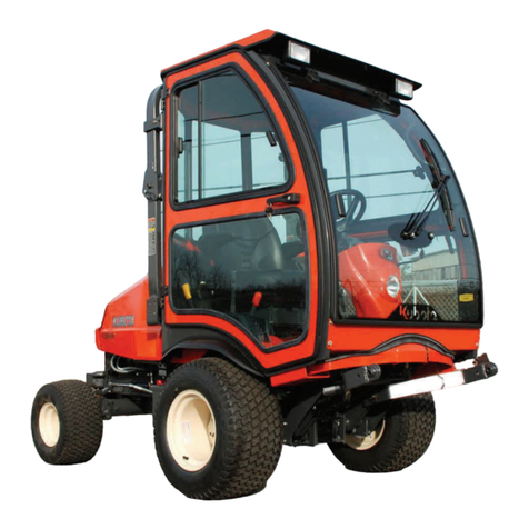
Kubota BX80 User manual

OWNER’S MANUAL
PLEASE READ THIS MANUAL CAREFULLY
KEEP READY AT ALL TIMES
BX-80 SERIES FRONT WIPER
P/N BX4072
MANUAL P/N: IM-BX4072
MANUAL P/N: 77700-08651
WIPER
MOTOR
For use with: BX4070 AND BX4090 CAB SYSTEMS FOR
KUBOTA BX1880, 2380, 2680 AND 23S TRACTORS
Rev. B, 02/21/2024

2
All products are designed to give safe, dependable service if they are operated and maintained ac-
cording to the instructions. Read and understand this manual before operation. It is the own-
er’s responsibility to be certain anyone operating this product reads this manual, and all other ap-
plicable manuals, to become familiar with this equipment and all safety precautions. Failure to do
so could result in serious personal injury or equipment damage. If you have any questions, consult
your dealer.
California Proposition 65
WARNING
Engine exhaust, some of its constituents,
certain machine components and fluids,
contain or emit chemicals known to the
State of California to cause cancer and
birth defects or other reproductive harm.
Legal Disclaimer
Kubota Corporation notes that specifications and technical information are subject to change
without notice and Kubota does not represent or warrant that the information in this publication
is completely accurate or current; however, Kubota used reasonable efforts to set forth and
include accurate and up to date information in this publication. Kubota disclaims all
representations and warranties, whether express or implied, including, but not limited to,
warranties of merchantability and fitness for a particular purpose and Kubota shall not be liable
for any damages, whether compensatory, direct, indirect, incidental, special, or consequential,
arising out of or in connection with the use of this publication, or the information therein.
The Product(s) described in this Publication are designed and manufactured only for the
country in which they are initially wholesaled by Kubota. Kubota does not provide parts,
warranty or service for any Product which is re-sold or retailed in any country other than the
country for which the Product(s) were designed or manufactured.
SAFETY FIRST
This symbol, the industry’s “Safety Alert Symbol”, is used throughout this manual
and on labels on the machine itself to warn of the possibility of personal injury.
Read these instructions carefully. It is essential that you read the instructions and
safety regulations before you attempt to assemble or use this unit.
Indicates an imminently hazardous situation which, if
not avoided, will result in death or serious injury.
DANGER:
WARNING:
CAUTION:
IMPORTANT:
NOTE:
Indicates a potentially hazardous situation which, if not
avoided, could result in death or serious injury.
Indicates a potentially hazardous situation which, if not
avoided, may result in minor or moderate injury.
Indicates that equipment or property damage could
result if instructions are not followed.
Gives helpful information.

3
GENERAL SAFETY INFORMATION
BEFORE YOU START SERVICE
• Read all instructions and safety instructions in this
manual and on your machine safety decals.
• Clean the work area and machine.
• Park the machine on a stable and level ground, and
set parking brake.
• Lower the implement to the ground.
• Stop the engine, then remove the key.
• Disconnect the battery negative cable.
• Hang a “DO NOT OPERATE” tag in the operator
station.
• When performing maintenance on the equipment,
hang the DO NOT OPERATE sign where it will be
obvious from and around the driver’s seat
• When performing maintenance or repairs, always
lower attachments to the ground, stop the engine
and secure the tracks with blocks.
• When performing maintenance on the equipment,
always disconnect the negative battery cable.
• Before using tools, make sure you understand how
to use them correctly and use tools in good condition
and of the right size for the job.
START SAFELY
• Do not do the procedures below when you start the
engine
- short across starter terminals
- bypass the safety start switch
• Do not alter or remove any part of machine safety
system.
• Before you start the engine, make sure that all shift
levers are in neutral positions or in disengaged
position.
• Do not start the engine when you stay on the
ground. Start the engine only from operator’s seat.
STARTING THE MACHINE SAFELY
• Before starting the engine, always sit in the driver’s
seat and make sure the area is safe and clear.
• As it is dangerous, never start the engine from
anywhere but the driver’s seat
• Always check and make sure control lever(s) are not
engaged before starting the engine.
• Never start the engine by hot-wiring the starter
circuit. This is not only dangerous, but may damage
the machine.
• Wear clothes appropriate for working on equipment.
Do not wear loose-fitting clothes as they may catch
on the machine controls.
• When working on the equipment, use all safety gear,
such as a helmet, safety glasses and shoes, that are
required by law or regulation.
• Never perform maintenance while drowsy or under
the influence of alcohol or drugs.
BE READY FOR AN EMERGENCY
• Keep a first-aid kit and fire extinguisher close at
hand so you can use it when needed.
• Keep emergency contact information for doctors,
hospitals and ERs handy.
KEEP A GOOD AIRFLOW IN THE WORK AREA
• If the engine is in operation, make sure that the area
has good airflow. Do not operate the engine in a
closed area. The exhaust gas contains poisonous
carbon monoxide.
NO SMOKING OR OPEN FLAMES WHILE FUELING
• Fuel is extremely flammable and dangerous. Never
smoke near fuel. If fuel is spilled on the machine, its
engine, or electrical parts, it may cause a fire. If fuel
is spilled, wipe it all up immediately.
• Never smoke while filling machine with fuel. And
always tighten the fuel cap securely and wipe up any
spilled fuel.
• Before getting on/off of the machine, clean off
around the steps so there is no mud on them.
Always give yourself 3-point support when getting
on/off the machine
CAUTION
• 3-point support means using both legs and
one hand or both hands and one leg as you
climb up/down.
• Do not remove the radiator cap when the engine
operates, or immediately after it stops. If not, hot
water can spout out from radiator. Only remove the
radiator cap when it is at a sufficiently low tempera-
ture to touch with bare hands. Slowly loosen the cap
to release the pressure before you remove it fully.
• The engine, muffler, radiator, hydraulic line, etc.,
have parts that remain very hot even after the engine
has been stopped. Be sure to avoid these parts, as
touching them can result in burns. Radiator coolant,
hydraulic fluid and oil also remain hot. Therefore, do
not attempt to remove caps and plugs, etc., before
these fluids have sufficiently cooled.
• Make sure the coolant temperature has dropped
sufficiently before opening the radiator cap. Also
since the inside of the radiator is pressurized, when
removing the cap, first loosen it to release the
pressure before removing the cap completely.
• Grease is under high pressure inside the hydraulic
cylinder. It is very dangerous to loosen a grease
nipple quickly as it may shoot off. Always loosen
grease nipples slowly.
• And never face a grease nipple while loosening it.
• The pressure in the hydraulic circuit stays at pres-
sure even after the engine stops. Before removing
parts, such as hydraulic devices from the machine,
first release the pressure. Please note that when
releasing residual pressure, the machine itself and/or
implements may move without warning, so be very
careful when releasing the pressure.
• Oil gushing out under pressure is extremely danger-
ous as it may pierce your skin or your eyes. Similar-
ly, oil leaking out of pinholes is not visible. So when
checking for oil leaks, always wear safety glasses
and gloves and use a piece of cardboard or a wood
block to shield yourself from oil.
• Do no open a fuel system under high pressure. The
fluid under high pressure that stays in fuel lines can
cause serious injury. Do not disconnect or repair the
fuel lines, sensors, or any other components be-
tween the fuel pump and injectors on engine with a
common rail fuel system under high pressure.
• Put on an applicable ear protective device (earmuffs
or earplugs) to prevent injury against loud noises.
• Be careful about electric shock. The engine gener-
ates a high voltage of more that DC100 V in the ECU
and is applied to injector.

4
GENERAL SAFETY INFORMATION
PREVENT A FIRE
• Fuel is very flammable and explosive under some
conditions. Do not smoke or let flames or sparks in
your work area.
• To prevent sparks from an accidental short circuit,
always disconnect the battery negative cable first
and connect it last.
• The battery gas can cause an explosion. Keep the
sparks and open flame away from the top of battery.
Especially when you charge the battery.
• Make sure that you do not spill fuel on the engine.
DISPOSE OF WASTE FLUIDS PROPERLY
• Never dispose of waste fluids on the ground, in
the gutter, a river, pond or lake. Always dispose
of hazardous substances like waste oil, coolant
and electrolytic fluid in accordance with the
relevant environmental protection regulations.
• Keep the safety plates clean so they can be
read. If a safety plate is damaged and comes off
or becomes illegible, put a plate with the same
warnings back in its place.
(1) SAFETY STAND
• When you need to access the underside of the
machine for maintenance purposes, be sure to
support the machine with a safety stand. Getting
under the machine while supporting the machine by
machine’s own hydraulic cylinder or using a hydrau-
lic jack can be extremely dangerous in the event of a
hydraulic fluid leakage or similar mishap.
• Whenever it is necessary to open the engine covers
or hood in order to service the machine, always prop
them open.
• If it is absolutely necessary to run the engine while
working on the machine, make sure you are clear of
all rotating or moving parts. Also take care not to
leave anything, such as tools or rags, near any
moving parts.
LOADER AND BACKHOE SAFETY
• Engage the loader control valve lock to prevent
accidental actuation when the implement is not in
use or during transport. Do not utilize the valve lock
for machine maintenance or repair.
• Engage the loader control valve lock to prevent
accidental actuation when the implement is not in
use or during transport. Do not utilize the valve lock
for machine maintenance or repair.
• Do not perform machine maintenance with loader in
the air. If possible, follow loader instructions to
remove loader before performing maintenance.
• If the machine has a backhoe, engage swing and
boom locks

5
ESTIMATED ASSEMBLY TIME
Refer to the following table for the estimated assembly time to open the packaging and assemble
the accessory.
Approximate Installation Time 30 minutes
Assembly times on the table are just reference under the average conditions with following
assumption(s)
1. Assembly is done by one worker
2. The following tools are readily available:
1) 3/8” Drive Ratchet and Long Drive Extension
2) Torque Wrench (inch-pounds)
3) 2.5mm Allen Wrench
4) 3/16 Allen Wrench
5) 1/2” Socket
6) 7/16” Socket
7) 7mm Open End Wrench
8) 8mm Open End Wrench
9) 21mm Open End Wrench
10) Flat Head Screw Driver
11) #2 Phillips Screw Driver
ASSEMBLY
All installation procedures listed within this manual are generally representative of the machine
model for which the manual is written. Your machine may be configured differently (e.g. SP1 vs. SP2,
etc.), but the outline for the procedure should still be followed. For further support for any issues not covered
within the pages of this manual, please contact your local Kubota representative.
WARNING:
TO PREVENT SERIOUS PERSONAL INJURY OR DEATH:
REQUIRED BEFORE INSTALLATION:
1. Read and understand this entire manual and any other publications for the equipment being operated.
2. Ensure that the surrounding area is clear and that personnel are positioned away from the area where
engagement and disengagement of attachments will occur.
3. Always shut off engine when leaving the operator’s area to perform any portion of the listed procedures.

ASSEMBLY
6
Steps 1-2 are only required if a cab has already been fully
installed.
If a cab is currently being installed for the first time, proceed
to step 3.
1. Remove installed roof and set aside with mounting
hardware.
Tools: 3/16 Allen Wrench
1/2” Socket
Figure 3: Remove Windshield Plugs
Figure 1: Remove Roof
Figure 2: Disconnect Weatherproof Connector
2. Disconnect the weatherproof connector from the main
power harness protruding from the bottom of the right
sideframe.
Disconnect
3. Remove and discard the (2) plugs found on the
windshield.
WARNING: Avoid damage! Do not pry against the
windshield to remove the plugs from outside the cab. Push
them out from inside the cab.

ASSEMBLY
7
Figure 4: Remove and Discard Dome Plugs
4. Remove (1) dome plug on the underside of the
windshield near the Rocker Switch hole plugs. Next,
remove the larger dome plug above the previously
removed hole plugs found in the windshield.
5. Install the wiper motor using the hardware provided on
the wiper motor and in the wiper motor mounting kit.
Tools: 21mm Open End Wrench
7/16” Socket
Torque Wrech
Note: Tighten the bolts at this time. Tighten the hex nut on
the motor shaft to 30 inch-lbs. and the 1/4-20 hex head bolt
to 75 inch-lbs..
WARNING: Over tightening wiper mounting hardware
can damage windshield and components. Tighten only
to specified values.
Hex Nut
1/4” Lock
Washer
1/4” Hex
Head Screw
Black Plastic
Standoff
Large Collar
Bushing
Small Collar
Bushing
Cap Nut
Rubber
Washer
Plastic
Washer
Plastic
Washer
Rubber
Washer
6. Install the circuit breaker on the inside of the windshield
support using the supplied thumb nut. Make sure
that the marking for terminal “1” is on the front right side
as shown. Next, install the supplied rubber grommet
into the bottom of the windshield support right above
the wiper motor.
Figure 6: Install Circuit Breaker & Grommet
“1”
Figure 5: Install Wiper Motor
Motor Shaft

ASSEMBLY
8
7. Connect the supplied front wiper wire harness to the
wiper motor and run the harness through the rubber
grommet.
Figure 7: Install Wiper Wire Harness
Figure 8: Connect Red Wire
White Power Wire
Red Jumper Wire to Additional
Breaker if Required
8. Connect the white power wire extending from the top of
the sideframe to terminal “1” found on the circuit
breaker.
Note: If additional accessories will be installed, install
the supplied jumper wire to terminal “1” and connect
the white power wire to the male portion of the
piggyback terminal. Connect the open end of the
jumper wire to terminal “1” on the next circuit breaker.
Next, install the red wire found on the front wiper
harness to terminal “2” found on circuit breaker.
Black Power Wire
Figure 9: Connect Black Wire
9. Connect the black power wire extending from the top of
the right sideframe onto the ground strip. Next, place
the black wire found on the front wiper wire harness
onto the same ground strip.
10. If there are any additional electrical accessories being
installed, install them now.
Red Accessory Wire
Connect Black Accessory
Wire here

ASSEMBLY
9
Figure 11: Connect Weatherproof Connector
11. If cab has been previously installed, re-connect the
weatherproof connector and processed to step 12. If
not, connect the weatherproof connector from the main
power harness previously installed to the connector on
the harness protruding from the bottom of the right
sideframe. Be sure to route the harnesses to avoid
sagging. Pull any excess wire back into the battery
compartment and secure with cable ties provided in the
cab hardware box.
Length Adjustment Tab
Set Screw
Angle Adjustment
Bolt
Figure 12: Power Up Wiper Motor
12. Turn the key to the on position and turn on the wiper
motor to make sure the motor functions.
ON
OFF
Figure 13: Install Wiper Blade onto Wiper Arm
Figure 14: Install Wiper Arm onto Wiper Motor Shaft
13. Remove the screw and locknut found on the wiper arm.
Insert the screw through the wiper arm, then upper
mounting hole in the wiper blade and through the wiper
arm securing with the locknut.
Tools: 7mm Open End Wrench
8mm Open End Wrench
14. Make sure the (2) set screws found on the wiper arm
are backed out enough to install the wiper arm onto the
wiper motor shaft. Install the wiper arm at the six (6)
o’clock position onto the wiper motor. Snug set screws.
Do not fully tighten. Turn the wiper motor on and test its
operation. Adjust the arm sweep by turning the blade,
adjusting the arm length, or removing the wiper arm off
of the wiper motor shaft
and reinstalling it at a different position.
Tools: 2.5mm Allen Wrench

ASSEMBLY
10
15. Next, tighten down the (2) set screws found on the
wiper arm (180 degrees apart) to ensure that the arm
does not work its way off the splined shaft of the motor.
Tighten to 24 inch-pounds max.
Tools: 2.5mm Allen Wrench
Torque Wrench
If the cab assembly has not been completed yet, continue
with the remaining steps to complete the cab installation. If
the cab was previously installed, procced to the next step.
Set
Screw
Figure 15: Wiper Arm Set Screw(s)
16. Re-install the roof using the fastening order shown.
Do not overtighten as damage to the plastic will occur.
Hand tighten until the rubber washer just begins to
bulge from under the steel fender washer.
Hardware previously removed (Reference only)
(6) 5/16-18 x 3/4” Flange bolts
(6) 5/16”ID x 1-1/4”OD Steel Fender Washers
(6) 5/16”ID x 1-1/4”OD Rubber Fender Washers
(6) 5/16-18 Flange nuts
Tools: 3/16 Allen Wrench
1/2” Socket
Figure 16: Re-Install Roof
(6) Flange Bolts
(6) Steel Washers
(6) Rubber Washers
(6) Flange Nuts

11
OPERATION
WARNING
REQUIRED BEFORE OPERATION
1. Read and understand this entire manual and any other publications for the equipment being operated.
2. Ensure that the surrounding area is clear and that personnel are positioned away from the area where engagement
and disengagement of attachments will occur
3. Always shut off engine when leaving the operator’s area to perform any portion of the listed procedures
ON
OFF
CIRCUIT
BREAKER
WIPER ANGLE
ADJUSTMENT
MOTOR
SWITCH
WIPER ARM LENTGH
ADJUSTMENT

12
TROUBLESHOOTING
Condition Possible Solution
• Front Wiper Motor does not turn on • Is the battery dead?
• Check the following electrical connections in order: wiper
motor to wiper harness, power harness to main harness
found on the lower part of the right sideframe, power harness
to battery, main harness to ground strip, main harness to
circuit breaker, jumpers to circuit breaker(s), wiper harness to
ground strip, wiper harness to circuit breaker.
FRONT WIPER TROUBLESHOOTING

PARTS BREAKDOWN
13
ITEM #: PART NUMBER: CODE NUMBER: QTY/KIT: DESCRIPTION:
170000-01056 9PWM852 1WIPER MOTOR, 85 DEGREE
270000-01054 9PWA14-16 1WIPER ARM, ADJUSTABLE LENGTH (11" - 16")
370000-01055 9PWB20-FB 1WIPER BLADE, 20", FLEX
477700-08630 9PWK-HBOEM 1GLASS MOUNTING KIT FOR WIPER SYSTEMS, O.E.M.
577700-08625 9SV-APBR 1ETA 5 AMP PUSH BUTTON RESET BREAKER W/ NUT
677700-08631 WH-00036 1FRONT WIPER HARNESS, BX80
777700-08628 WH-00035 1WIRE HARNESS, POWER JUMPER, BX80
--- 77700-08651 IM-BX4072 1INSTALL INSTRUCTIONS (NOT SHOWN)
123
456
7
Other manuals for BX80
2
This manual suits for next models
1
Table of contents
Other Kubota Tractor Accessories manuals

Kubota
Kubota 77700-VC5040 User manual

Kubota
Kubota VC5045 User manual

Kubota
Kubota 2491 User manual

Kubota
Kubota B01 Series Operating instructions

Kubota
Kubota AP-SSP1572 User manual

Kubota
Kubota AP-SR2672 User manual

Kubota
Kubota F5205 Installation instructions

Kubota
Kubota 77700-12652 User manual

Kubota
Kubota BX25 Deluxe ROPS Cab User manual

Kubota
Kubota GCD 450 H Quick start guide