Kubota VC5045 User manual

OWNER’S MANUAL
MANUAL P/N: 77700-07221
PLEASE READ THIS MANUAL CAREFULLY
KEEP READY AT ALL TIMES
CAB ENCLOSURE
p/n: 77700-VC5045 (VC5045)
For use with KUBOTA RTV X1140
Rev. D, 05/19/2022

This is the owner’s manual for the Cab Enclosure kit for the Kubota RTV X1140. This manual includes installation of
the cab onto the vehicle, and notes for conversion of the vehicle from four to two passenger modes as it relates to the
cab.
IMPORTANT:
• Windshield assembly (VC5025, VC5023, or VC5020) must be installed prior to installation of cab enclosure.
• If installing work lights, it will ease assembly to install lights onto the canopy prior to installing canopy onto vehicle.
• If installing a 4-way flasher kit, it will ease assembly to install lights onto the rear header before installing header to
vehicle.
• If installing a Vinyl Center Curtain, the curtain must be installed prior to installing canopy onto vehicle.
Approximate installation time: 4 Hours (not including accessories or other cab components)
INTRODUCTION
1
California Proposition 65
WARNING
Engine exhaust, some of its constituents,
certain vehicle components and fluids,
contain or emit chemicals known to the
State of California to cause cancer and birth
defects or other reproductive harm.
SAFETY FIRST
This symbol, the industry’s “Safety Alert Symbol”, is used throughout this manual and
on labels on the machine itself to warn of the possibility of personal injury. Read these
instructions carefully. It is essential that you read the instructions and safety regulations
before you attempt to assemble or use this unit.
Indicates an imminently hazardous situation which, if not
avoided, will result in death or serious injury.
DANGER:
WARNING:
CAUTION:
IMPORTANT:
NOTE:
Indicates a potentially hazardous situation which, if not
avoided, could result in death or serious injury.
Indicates a potentially hazardous situation which, if not
avoided, may result in minor or moderate injury.
Indicates that equipment or property damage could re-
sult if instructions are not followed.
Gives helpful information.
Legal Disclaimer
Kubota Corporation notes that specifications and technical information are subject to
change without notice and Kubota does not represent or warrant that the information
in this publication is completely accurate or current; however, Kubota used
reasonable efforts to set forth and include accurate and up to date information in this
publication. Kubota disclaims all representations and warranties, whether express or
implied, including, but not limited to, warranties of merchantability and fitness for a
particular purpose and Kubota shall not be liable for any damages, whether
compensatory, direct, indirect, incidental, special, or consequential, arising out of or in
connection with the use of this publication, or the information therein.
The Product(s) described in this Publication are designed and manufactured only for
the country in which they are initially wholesaled by Kubota. Kubota does not provide
parts, warranty or service for any Product which is re-sold or retailed in any country
other than the country for which the Product(s) were designed or manufactured.

INTRODUCTION 1
TABLE OF CONTENTS 2
SAFETY INFORMATION 3
GENERAL SAFETY INFORMATION 4
OPERATION 7
INSTALLATION 9
TROUBLESHOOTING 22
SERVICE PARTS BREAKDOWN 23
TABLE OF CONTENTS
2

WARNING:
TO PREVENT SERIOUS PERSONAL INJURY OR DEATH:
• This cab enclosure adds an additional 335lbs (152Kg) to the weight of the base vehicle, not
including Windshield, Canopy or other accessories. Deduct the accessory’s total weight from
the vehicle’s rated capacity including driver and passenger. Never operate the vehicle outside
of its rated weight capacity. The additional weight could affect the center of gravity of the unit,
therefore additional care should be taken during operation.
• Use proper personal protective equipment during all phases of installation, removal and
operation.
• Exposure to Carbon Monoxide can cause illness, serious injury or death.
Never operate vehicle if suspicious of Carbon Monoxide. Inspect exhaust system for leaks
monthly. Leaks can result from loose connections, corrosion, cracks or other damage to the
exhaust manifold. If leaks are found, repair or replace exhaust system. Do not use vehicle until
repair or replacement is complete.
Serious injury or death:
• This cab enclosure does not provide protection from rollover or other accidents.
• This cab enclosure does not provide protection from flying objects including golf balls.
• This cab enclosure does not provide protection from lightning. When lightning threatens, take
cover and do not operate vehicle.
SAFETY INFORMATION
3

GENERAL SAFETY INFORMATION
4
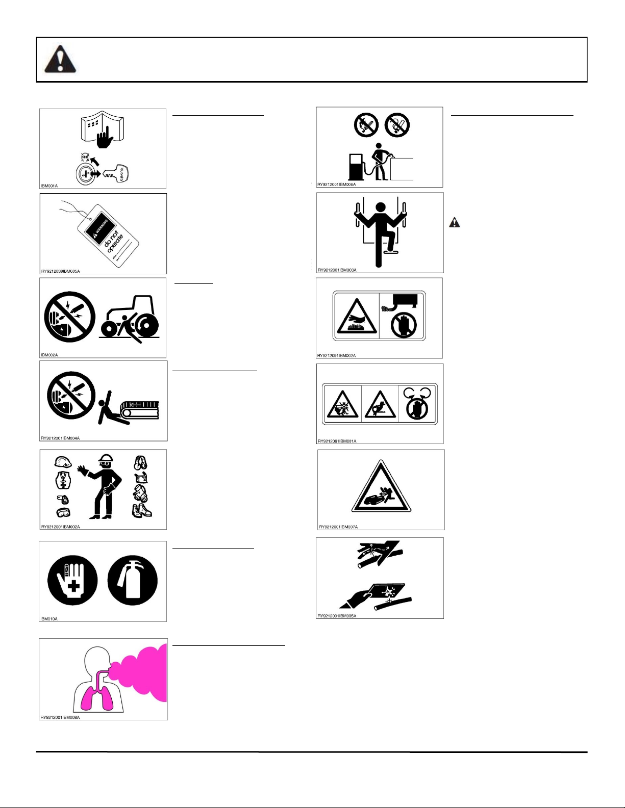
BEFORE YOU START SERVICE
• Read all instructions and safety instructions in this
manual and on your machine safety decals.
• Clean the work area and machine.
• Park the machine on a stable and level ground, and
set parking brake.
• Lower the implement to the ground.
• Stop the engine, then remove the key.
• Disconnect the battery negative cable.
• Hang a “DO NOT OPERATE” tag in the operator
station.
WSM000001INI0010US0
• When performing maintenance on the equipment,
hang the DO NOT OPERATE sign where it will be
obvious from and around the driver’s seat
• When performing maintenance or repairs, always
lower attachments to the ground, stop the engine
and secure the tracks with blocks.
• When performing maintenance on the equipment,
always disconnect the negative battery cable.
• Before using tools, make sure you understand how
to use them correctly and use tools in good condi-
tion and of the right size for the job.
RY9212038INI0002US0
START SAFELY
• Do not do the procedures below when you start the
engine
- short across starter terminals
- bypass the safety start switch
• Do not alter or remove an part of machine safety
system.
• Before you start the engine, make sure that all shift
levers are in neutral positions or in disengaged
position.
• Do not start the engine when you stay on the
ground. Start the engine only from operator’s seat.
WSM00001INI0015US0
STARTING THE MACHINE SAFELY
• Before starting the engine, always sit in the driver’s
seat and make sure the area is safe and clear.
• As it is dangerous, never start the engine from
anywhere but the driver’s seat
• Always check and make sure control lever(s) are
not engaged before starting the engine.
• Never start the engine by hot-wiring the starter
circuit. This is not only dangerous, but many
damage the machine.
RY9212001INI0008US0
• Wear clothes appropriate for working on equip-
ment. Do not wear loose-fitting clothes as they may
catch on the machine controls.
• When working on the equipment, use all safety
gear, such as a helmet, safety glasses and shoes,
that are required by law or regulation.
• Never perform maintenance while drowsy or under
the influence of alcohol or drugs.
RY9212001INI000US0
BE READY FOR AN EMERGENCY
• Keep a first-aid kit and fire extinguisher close at
hand so you can use it when needed.
• Keep emergency contact information for doctors,
hospitals and ERs handy.
RY9212001INI0004US0
KEEP A GOOD AIRFLOW IN THE WORK AREA
• If the engine is in operation, make sure that the
area has good airflow. Do not operate the engine
in a closed area. The exhaust gas contains
poisonous carbon monoxide.
WSM000001IN006US0
NO SMOKING OR OPEN FLAMES WHILE FUELING
• Fuel is extremely flammable and dangerous.
Never smoke near fuel. IF fuel is spilled on the
machine, its engine, or electrical parts, it may
cause a fire. If fuel is spilled, wipe it all up
immediately.
• Never smoke while filling machine with fuel. And
always tighten the fuel cap securely and wipe up
any spilled fuel.
RY9212001INI0012US0
• Before getting of/off of the machine, clean off
around the steps so there is no mud on them.
Always give yourself 3-point support when getting
on/off the machine
CAUTION
• 3-point support means using both legs and
one hang or both hands and one leg as you
climb up/down.
RY9212038INI0003US0
• Do not remove the radiator cap when the engine
operates, or immediately after it stops. If not, hot
water can spout out from radiator. Only remove
the radiator cap when it is at a sufficiently low
temperature to touch with bare hangs. Slowly
loosen the cap to release the pressure before you
remove it fully.
• The engine, muffler, radiator, hydraulic line, etc.,
have parts that remain very hot even after the
engine has been stopped. Be sure to avoid these
parts, as touching them can result in burns.
Radiator coolant, hydraulic fluid and oil also
remain hot. Therefore, do not attempt to remove
caps and plugs, etc., before these fluids have
sufficiently cooled.
• Make sure the coolant temperature has dropped
sufficiently before opening the radiator cap. Also
since the inside of the radiator is pressurized,
when removing the cap, first loosen it to release
the pressure before removing the cap completely.
• Grease is under high pressure inside the
hydraulic cylinder. It is very dangerous to
loosen a grease nipple quickly as it may shoot
off. Always loosen grease nipples slowly.
• And never face a grease nipple while loosening
it.
• The pressure in the hydraulic circuit stays at
pressure even after the engine stops. Before
removing parts, such as hydraulic devices from
the machine, first release the pressure. Please
not that when releasing residual pressure, the
machine itself and/or implements may move
without warning, so be very careful hen releasing
the pressure.
• Oil gushing out under pressure is extremely
dangerous as it may pierce your skin or your
eyes. Similarly, oil leaking out of pinholes is not
visible. So when checking for oil leaks, always
wear safety glasses and gloves and use a piece
of cardboard or a woo block to shield yourself
from oil.
• Do no open a fuel system under high pressure.
The fluid under high pressure the stays in fuel
lines can cause serious injury. Do not disconnect
or repair the fuel lines, sensors, or any other
components between the fuel pump and injectors
on engine with a common rail fuel system under
high pressure.
• Put on an applicable ear protective device
(earmuffs or earplugs) to prevent injury against
loud noises.
• Be careful about electric shock. The engine
generates a high voltage of more that DC100 V in
the ECU and is applied to injector.

GENERAL SAFETY INFORMATION
5
PREVENT A FIRE
• Fuel is very flammable and explosive under some
conditions. Do not smoke or let Flames or sparks in
your work area.
• To prevent sparks from an accidental short circuit,
always disconnect the battery negative cable first
and connect it last.
• The battery gas can cause an explosion. Keep the
sparks and open flame away from the top of battery.
Especially when you charge the battery.
• Make sure that you do not spill fuel on the engine.
WSM000001INI0005US0
DISPOSE OF WASTE FLUIDS PROPERLY
• Never dispose of waste fluids on the ground, in the
gutter, a river, pond or lake. Always dispose of
hazardous substances like waste oil, coolant and
electrolytic fluid in accordance with the relevant
environmental protection regulations.
• Keep the safety plates clean so they can be read. If
a safety plate is damaged and comes off or be-
comes illegible, put a plate with the same warnings
back in its place.
• Make sure the lift arm stopper is properly
engaged before performing any work beneath
raised lift arms. Never attempt to do any work
or move under the lift arms when they are not
properly supported.
• Keep in mind that the lift arms may fall whenev-
er hydraulic lines are disconnected, loosened,
or removed. Any malfunction or failure in the
hydraulics can also cause lift arms to drop.
• Always perform the necessary repairs or service
whenever the lift arm stopper becomes dam-
aged or malfunctioned, or parts are missing.
Damaged or malfunction the lift arm stopper
may cause the lift arms to fall causing serious
injury or death.
(1) Life arm stopper
• When you need to access the underside of the
machine for maintenance purposes, be sure to
support the machine with a safety stand.
Getting under the machine while supporting the
machine by machine’s own hydraulic cylinder or
using a hydraulic jack can be extremely danger-
ous in the event of a hydraulic fluid leakage or
similar mishap.
(1) Safety Stand
• Whenever it is necessary to open the engine
covers or hood in order to service the machine,
always prop them open.
• If it is absolutely necessary to run the engine
while working o the machine, make sure your
are clear of all rotating or moving parts. Also
take care not to leave anything, such as tools or
rages, near any moving parts.

IMPORTANT: Keep all decals clean and legible. Replace all missing, illegible, or damaged decals.
IMPORTANT: Decal placement locations shown are approximate; decals should not be placed in a location where the
operator’s field of view is impeded, and should not cover any portion of other decals installed in the same vicinity.
INSTALLING OR REPLACING DECALS: Thoroughly clean the area where decal is to be placed using mild soap and
water. Allow the surface to fully dry. Remove the backing from the decal, exposing the adhesive surface. Apply the
decal to the recommended position shown in the diagram below and smooth out any bubbles.
• WARNING: PINCH POINT - 9DL-150
Located on left and right sides of Lower Rear Panel
• CAUTION: NO STEP - 9DL-197
Located on top surface of left and right Fender Panels.
DECALS AND PLACEMENT
6
Lower rear panel
Rear fender panel (left)
1) WARNING: 9DL-150
CAUTION
2) CAUTION: 9DL-197
Lower rear panel
Rear fender panel (right)
1
1
2
2

CAUTION: To prevent injury: The additional latches, upper and lower rear panels present potential
pinch points which may cause personal injury.
IMPORTANT: The addition of a cab requires extra steps to convert from four passenger to two and back,
due to the rear panel latches, upper and lower rear panels.
Four Passenger to Two Passenger conversion:
1) Open both rear doors. Note: the rear doors may remain on the vehicle and will not interfere with the operation of the
cargo bed. The rear doors will latch securely in two-passenger mode.
2) Lift and rotate the seat bottom forward. IMPORTANT: if the rear seat is not forward, the rear seat back assembly
may damage the rear seat cushion.
3) Open both cabin rear panel latches by lifting the latch tab, rotating the tab counter-clockwise and pulling up on the
tab.
4) Pull up on the rear seat latch handle behind the driver’s side of the seat, lift and rotate the rear seat back assembly
forward. Secure the seat back with the rubber tethers on the front side of the rear passenger compartment.
5) Rotate the upper rear panel up and forward and lock the panel into the latch on the driver’s side.
6) Close or remove the rear doors as desired.
When converting from two passenger to four passenger:
Convert from two passenger to four passenger in reverse order of the above with the following exceptions:
• Release the upper rear panel from its latch first by pressing down on the release lever above the front of the upper
rear panel, on the driver’s side of the cab.
NOTE: The upper rear panel must be behind the lower rear panel for proper fit and seal.
• The lower rear panel may need to be shifted side to side to align to the fender panels.
• Make sure to lift the center seat belt catches above the seat bottom.
OPERATION
7
Rear Panel Latches
Latch keeper
Latch tab
Upper Rear Panel
Four Passenger configuration
(shown with doors removed)
Two Passenger configuration
Rear panel
latches
Upper rear
panel Latch for upper
rear panel
Latch
release
lever
Close latch
Open latch

CARE AND MAINTENANCE:
Check and tighten all hardware after 20 hours of operation. Periodically inspect and tighten hardware for the
remainder of the unit’s service life. Keep the enclosure components clean in order to prevent dust and dirt
from forming an unattractive film. The life of your cab components depend upon following these care proce-
dures:
1. NEVER USE AN ABRASIVE DETERGENT / VEHICLE CLEANER OR A WIRE BRISTLED BRUSH. Do
not use any CITRUS BASED CLEANERS such as orange or lemon.
2. NEVER USE AN ALCOHOL-BASED PRODUCT FOR CLEANING PLASTIC WINDOWS.
Do not use WINDEX, GLASS PLUS, FANTASTIC, etc. Use of these products will result in deterioration
of the plastic windows.
3. Clean the enclosure surfaces thoroughly with warm soapy water and a COTTON cloth or chamois. Be
sure to use mild soap, specifically a dish liquid or equivalent. Clean in a light circular motion for best
results.
4. Use EXTRA CAUTION when cleaning the interior of the enclosure. The interior is more sensitive than
the exterior.
5. Remove grease and oil with mineral spirits and a COTTON cloth or chamois.
OPERATION
8

All installation procedures listed within this manual are generally representative of the machine
model for which the manual is written. Your machine may be configured differently (e.g. SP1 vs. SP2,
etc.), but the outline for the procedure should still be followed. For further support for any issues not
covered within the pages of this manual, please contact your local Kubota representative.
WARNING:
TO PREVENT SERIOUS PERSONAL INJURY OR DEATH:
REQUIRED BEFORE INSTALLATION:
1. Read and understand this entire manual and any other publications for the equipment being operated.
2. Ensure that the surrounding area is clear and that personnel are positioned away from the area where
engagement and disengagement of attachments will occur.
3. Always shut off engine when leaving the operator’s area to perform any portion of the listed procedures.
IMPORTANT:
• Windshield assembly (VC5025, VC5023, or VC5020) must be installed prior to installation of cab
enclosure.
• If installing work lights, it will ease assembly to install lights onto the canopy prior to installing canopy
onto vehicle.
• If installing a 4-way flasher kit, it will ease assembly to install lights onto the rear header before installing
header to vehicle.
• If installing a Vinyl Center Curtain, the curtain must be installed prior to installing canopy onto vehicle.
TOOLS REQUIRED:
Open ended wrenches or sockets: Allen Wrenches (T-handle •Torque Wrench and Ratchet
•3/4” •17mm recommended): •Cordless drill and 11/32” drill bit
•1/2” •14mm •5mm •Needle Nose Pliers
•7/16” •12mm •5/32” •Grease
•3/8” •3/16” •Measuring Tape
STEP 1: Vehicle Preparation
• Convert the Cargo Bed into the shorter four-seat configuration, raise the Cargo Bed to its highest angle
and set the bed lock. The cargo bed should remain raised until cab installation is complete.
WARNING: TO PREVENT SERIOUS INJURY OR DEATH: Failure to install the lock on the cargo
bed may result in personal injury or damage to cab components
STEP 2: Canopy Mounts and Windshield
• Install the Canopy Mounts and Windshield per the windshield installation manual. Do not tighten any
bolts until the full cab assembly is complete.
NOTE: If a canopy is already installed on the vehicle, remove the canopy and retain all bolts, washers and
nuts used to secure the canopy. Re-install the (6) M10 bolts into the top of the vehicle ROPS. Remove
and discard the P-clamps that were holding the canopy.
INSTALLATION
9

STEP 3: Lower Rear Panel Mounts
3.1 Convert the rear seat into its forward, two-seat configuration.
3.2 Remove the bracket holding the seat support rod to the seat back (Figure 3.2) and install the Rear Panel Mount
between the bracket and the seat frame. Reinstall the seat support bracket with the original fastener. Align the
lower hole of the mount to the hole in the seat frame and install (1) flanged hex 1/4-20 x 3/4” bolt and flanged nut.
Repeat for the opposite side.
3.3 Torque both seat support bracket bolts to 19 ft-lbs. (25.8 N-m), and the lower 1/4-20 bolts to 10ft-lbs. (13.5 N-m).
STEP 4: Lower Rear
Panel
4.1 Move the seat back into its rear position and latch it into place.
4.2 IMPORTANT: Remove the protective film from the inside of the window on the lower rear panel.
4.3 Place the lower rear panel onto the seat back, with the tabs at the top of the panel hooked over the seat
screen frame (see Figure 4.1). Align the holes in the panel to the threaded inserts in the rear panel mounts
and secure the panel with (4) 5/16-18 x 3/4” bolts (see Figure 4.2). Center the lower rear panel on the rear
seat back and tighten the bolts snug.
INSTALLATION
10
Figure 3.2: Lower Rear Panel Mounts
Seat support bracket
1/4-20 bolts
and nuts
Rear panel mounts
Figure 4.1: Lower Rear Panel onto Seat Screen
Lower rear panel tabs
Seat screen frame
Figure 4.2: Lower Rear Panel onto Seat Screen
5/16” Bolts
3 of 4 shown

STEP 5: Rear Fender Panels
5.1 Move the rear seat back to its forward
position.
5.2 Remove the two plastic tree plugs shown
from the rear floor pan. Remove the M10
nut from the seat belt retractor for the rear
seat (see Figure 5.2). Do not remove the
seat belt retractor or washers.
5.3 Slide the fender panel under the frame for
the seat belt, over the stud for the seat
belt and outside the seat belt retractor
(see Figure 5.2). Install two 1/4-20 x 3/4”
button-head bolts and fender washers
through the floorboard and secure with
1/4-20 nuts under the floor pan (see
Figure 5.3). Leave loose.
5.4 Install the nut for the seat belt retractor,
set the slot of the fender bracket
approximately centered on the seat belt
stud and tighten snug. Ensure the seat
belt retractor rotates freely.
5.5 Repeat steps 5.2 through 5.4 for the other
side.
INSTALLATION
11
Figure 5.2: Rear Fender Panel (Driver’s side shown)
M10 nut
Plastic tree plugs:
Remove and discard
Figure 5.3: Rear Fender Panel (Driver’s side shown)
1/4-20 Bolts
and fender
washers
1/4-20 Nuts

STEP 6: B-Pillar Panels
6.1 For each side, remove and retain both M12 bolts at the base of the center, side pillar of the ROPS
(see Figure 6.1)
6.2 For each side, remove and retain the M10 bolt from the side of the ROPS, just forward of the center
pillar (see Figure 6.2). These bolts will be used later to secure the front side headers.
6.3 Place the B-Pillar over the center side ROPS pillar and secure it with the removed M12 bolts.
6.4 Adjust the B-pillar to be centered in the slots with the lower section of the B-pillar as close to parallel to
the ROPS as possible. Tighten the M12 bolts snug but do not apply final torque.
6.5 Install a floorboard bracket at the corner above the floorboard and inside the B-pillar (see Figure 6.1).
Attach the bracket to the B-pillar with (3) 5/16-18 X 3/4” flanged button head bolts and nuts inside.
Push the B-pillar against the floorboard to remove any gap and secure the bracket to the floorboard
with (2) 5/16-18 X 3/4” flanged button head bolts and nuts underneath. Tighten snug but do not apply
final torque.
6.6 Repeat for the other side.
INSTALLATION
12
Figure 6.1: B-Pillar center and lower bolts Figure 6.2: B-Pillar upper M10 bolt
M12 Bolts:
Remove and
re-use
M10 Bolt:
Remove and
retain
5/16-18 Nuts
5/16-18 Bolts
5/16-18 Bolts
5/16-18
Fender
Washers
B-Pillar Panel
Floorboard
Bracket

STEP 7: Front Side Header Assemblies
7.1 For each side, one side at a time, remove and retain the M10 bolt at the underside of the front end of the
front ROPS cross member, and the M10 bolt at the top of the ROPS above the B-pillar (see Figure 7.1).
7.2 Place each front side header over the ROPS and secure it to the underside of the ROPS with the removed
M10 bolt.
7.3 Install the M10 bolt removed in step 6.2 through the front header and B-pillar panel and into the ROPS.
Tighten both M10 bolts snug but do not apply final torque.
NOTE: The front header will be secured to the windshield frame after the rear doors are installed and adjusted.
The M10 bolt in the top of the ROPS will be installed with the canopy.
INSTALLATION
13
Figure 7.1: Front Side Headers (Driver’s side shown)
M10 Bolt:
Remove and
re-use
M10 Bolt
from step 6.2
M10 Bolt:
Remove and discard
(retain if Canopy had been installed)
Assemble
later

STEP 8: Rear Header Assemblies
8.1 For both sides, remove and retain the (2) M10 bolts at the outside, upper rear of the side of the ROPS (see
Figure 8.1). Do not remove or loosen the bolts on the inside of the ROPS.
8.2 Place the driver’s side rear side header over the ROPS and secure it with the removed bolts (see Figure
8.1). Leave the bolts loose. Ensure the latch is on the inside of the frame.
8.3 Secure the Side Header to the B-Pillar with (1) 5/16 x 3/4” bolt and nut. Leave loose.
8.4 Convert the rear seat to its forward position.
8.5 Loosen the bolt in the mirror mount on the ROPS and remove the rear mirror (see Figure 8.5).
NOTE: If installing a 4-way flasher kit (VC5057A), install the flashers to the rear header first before placing the
header on the vehicle frame.
8.6 With an assistant, place the rear header onto the rear ROPS and against the inside of the driver’s side
header and secure the rear header to the side header with (2) 5/16-18 x 3/4” bolts and nuts. Leave loose.
Place the passenger’s side header onto the frame and secure it with (2) M10 bolts from step 8.1, and (1)
5/16 x 3/4” bolt and nut to the B-pillar.
8.7 Secure the rear header to the passenger’s side header with (2) 5/16-18 x 3/4” bolts and nuts. Ensure the
top of the rear header is parallel to the top of the side headers and tighten the (4) 5/16” bolts for the rear
header snug.
8.8 Re-install the rear mirror onto the upper rear frame.
INSTALLATION
14
Figure 8.1: Rear Side Headers (Driver’s side shown)
5/16-18 Bolt
5/16-18 Nut
M10 Bolts:
Remove and re-use
Latch inside
ROPS frame
Figure 8.5: Rear header
Rear Mirror
Rubber flaps must be
inside side headers
5/16-18
Bolts
5/16-18 Nuts

STEP 8: Rear Header Assemblies (continued)
8.9 Measure the distance between the rear fenders and the rear side headers, just rear of the latch pin
washers, to the sheet metal surface of the panels.
8.10 Push up or down on the rear side headers to meet the following dimensions: (see Figure 8.10)
• Driver’s side: 49-7/8” ± 1/8” (1267mm ± 3mm)
• Passenger’s side: 46-7/8” ± 1/8” (1190mm ± 3mm)
If the header height is still too low or too high from header adjustment alone, push the headers up or down
as far as the slots will allow, then loosen the M10 nut for the seat belt retractor and push the fender panel
up or down to meet the required measurement within ± 1/8” (3mm).
NOTE: Left and right measurements differ due to the designs of the left and right fender to accommodate the
battery cover and fuel filler, respectively.
8.11 Tighten the (2) M10 bolts in each rear side header, the 5/16” bolt at the front of each side header and the
M10 nut at the seat belt retractor snug.
INSTALLATION
15
Figure 8.10: Rear Header Adjustment
Loosen here
to adjust
Fender panel
up or down
Fender latch pin
Header latch pin
Measure between
Fender Panel and
Rear Header, at rear
side of Latch Pins
Loosen here to
adjust Header
up or down

STEP 9: Upper Rear Panel
9.1 With assistance, align the upper rear panel to the hinge tabs of the upper header, with the rear panel
tabs to the inside of the rear header tabs. Secure the upper rear panel to the rear header with two
shoulder screws, 3/8” ID washers, plastic spacers and 5/16” nuts (see Figure 9.1). Torque to 16 ft-lbs.
(21.5 N-m).
9.2 Rotate the upper rear panel up and check alignment of the rear panel pin and latch on the driver’s
side. Adjust the latch and pin as needed until the panel latches fully and repeatably (see Figure 9.2).
INSTALLATION
16
Figure 9.2: Upper Rear Panel Latch Adjustment
Adjust latch
forward or back
Figure 9.1: Upper Rear Panel Hardware
Shoulder bolt
3/8” I.D.
Fender
washer
Plastic
bushing
5/16-18
nut Adjust pin
up or down

STEP 10: Lower Rear Panel Alignment
Install Rear Panel Latches
10.1 Unlatch the upper rear panel from the upper frame
and allow it to hang down, then move the rear seat
back to its rear position.
10.2 Shift the lower panel and rear seat back left or right
as needed to center it under the upper rear panel.
(see Figure 10.2). If more movement of the lower
panel is needed, loosen the (4) 5/16” lower bolts
and shift the lower rear panel left or right. Tighten
the bolts snug.
10.3 Using the holes in the upper portion of the lower
rear panel as a guide, drill (4) 11/32” holes though
the screen frame of the rear seat (see Figure 10.2).
10.4 For the upper (2) holes, place a rear panel bracket
inside the screen frame and under the rear panel
tabs (see Figure 10.4) and align the brackets to the
drilled holes. Install 5/16-18 x 1-1/2” bolts, 5/16” I.D.
rubber and steel fender washers and 5/16-18 nuts
through all (4) drilled holes in the rear panel and
screen frame. Tighten snug.
10.5 Install one rear panel latch mount to each rear panel
tab and bracket with (2) flanged hex 1/4-20 x 3/4”
bolts and flanged nuts per latch (see Figure 10.5).
Leave loose.
10.6 Open the rear panel latches on the lower rear panel
by lifting the tab and rotating the tab counter-
clockwise. Hook the latch onto the keeper on the
upper rear panel and slightly rotate the latch tab
clockwise to partially close (see Figure 10.5).
10.7 Raise or lower the latch mount until the mount
contacts the upper rear panel frame and fully close
the latch. Repeat for both latches and tighten the (4)
1/4” bolts snug.
INSTALLATION
17
Figure 10.2: Lower Rear Panel
Drill through here
4 places
5/16” Bolts
3 of 4 shown
5/16-18 x 1-1/2” Bolt
Figure 10.4: Rear Panel to Screen bolts
Note: upper mounting hole shown.
5/16 x 1-1/4”
Rubber Fender
Washer
5/16” x 1-1/4” Steel
Fender Washer
5/16-18 Nut
Rear panel bracket
Figure 10.5: Rear Panel Latches
Latch keeper
Latch tab
Mount
tabs
1/4-20 bolts, nuts
behind bracket
Adjust bracket
up or down
Check upper and lower rear
panel alignment at these corners
Close latch
Open latch

STEP 11: Fender Alignment
11.1 Ensure the lower rear panel is centered under the upper rear panel. If necessary, loosen the latches at
the top of the lower rear panel and shift the lower rear panel left or right.
11.2 Loosen the (2) 5/16” nuts at the rear of each fender panel and shift the rear of the fender panel left or
right to align the outer surface to the bottom of the lower rear panel (see Figure 11.2). Tighten the
5/16” nuts snug.
STEP 12: Rear Door Installation.
12.1 Install a total of (4) Brass Washers onto the weld-on
hinge pins on the B-Pillars, one washer per pin (see
Figure 12.1).
12.2 Apply Grease to the Hinge Pins on the B-pillars.
12.3 Holding the door perpendicular to the vehicle, lower
the door hinge sleeves over the pins on the vehicle
(see Figure 12.1).
NOTE: If the hinge sleeves don’t line up with the hinge
pins, loosen factory installed door hinges until
fasteners are finger tight, then repeat this step,
aligning the sleeves to the pins, as necessary.
12.4 Rotate the door open and closed until the hinge
sleeves seat properly on the brass washers. It may
be necessary to manipulate the angle of the hinges
by hand to get them to fully seat on the brass
washers.
12.5 Gently close the door, lifting on the door handle if
necessary, to allow the latches to lock around the
striker pins. Ensure that you have heard (2) clicks of
both latches.
NOTE: The rear doors have two latches, one at each rear
corner of the door.
INSTALLATION
18
Figure 11.2: Rear Fender Adjustment
Loosen
these nuts Align these
surfaces
Figure 12.1: Rear Door Installation (Driver’s side shown)
Gas Spring (short)
Brass Washer
Brass Washer
Upper door latch
Lower door latch

STEP 13: Rear Door Adjustment
13.1 Tighten the rear door hinges enough to remove slack yet still allow the door to hinge bolts to slide
within the slots of the hinges. Shift the door to align the top of the door roughly parallel door to the top
of the rear side header.
13.2 Check the vertical alignment of the door to the striker pins. Readjust as needed via the door hinges if
the door latches are less than 1/16” from either striker pin washer.
13.3 If more adjustment is needed:
• The rear header assembly may be moved up or down (see Step 8).
• The fender panel may be adjusted up or down after loosening the bolt at the seat belt mount.
• The B-Pillar can be shifted to rotate the hinge pin alignment. Loosen all bolts in the B-Pillar as well
as the two M10 bolts in each side header to adjust.
13.4 Once the latches are aligned vertically, adjust both striker pins back or forth to align to the latches.
13.5 Tighten all hinge bolts, striker pins and any bolts loosened for adjustment snug.
13.6 Ensure the door latches consistently with (2) clicks of both latches, and opens consistently with both
the inside and outside handles. Readjust if needed.
13.7 Open door to slightly less than 90°. Install the shorter pair of gas springs onto the rear door and rear
side header ball studs with the red tab quick release end on the side header (see Figure 12.1).
STEP 14: Canopy, Center Panel and Accessories
14.1 If installing a Vinyl center panel, VC5047, install it at this time per the instructions included with the
panel, prior to installing the canopy.
14.2 If installing a Center Panel with Slider, VC5046, install it at this time per the instructions included with
the panel.
14.3 Apply the 1/2” V-groove weather seal along the top perimeter of the cab (see Figure 14.3). Start at
the seal on the windshield and route the seal to the rear along the edge of the side headers. Continue
along the rear header and forward along the front headers up to the seal on the opposite side of the
windshield.
14.4 Apply 1/2” foam weather seal to the upper center beam of the ROPS, along the center of the beam
and up to the v-groove seal on each side (see Figure 14.3).
14.5 Install the plastic or steel canopy at this time per the instructions included with the canopy kit. Note
that the canopy will use the holes in the cab enclosure and does not require the P-clamps included
with the canopy kit.
INSTALLATION
19
Figure 14.3: Canopy Weather Seal
Start and end
V-groove seal at
windshield rubber
Foam seal
This manual suits for next models
1
Table of contents
Other Kubota Tractor Accessories manuals

Kubota
Kubota 2409 User manual

Kubota
Kubota 77700-12652 User manual

Kubota
Kubota B01 Series Operating instructions

Kubota
Kubota AP-SR2672 User manual

Kubota
Kubota 2491 User manual

Kubota
Kubota 77700-VC5040 User manual

Kubota
Kubota AP-SSP1572 User manual

Kubota
Kubota AP-SG2572 User manual

Kubota
Kubota BX80 User manual

Kubota
Kubota BX80 User manual