Safety
Improperuseormaintenancebytheoperatoror
ownercanresultininjury.Toreducethepotential
forinjury,complywiththesesafetyinstructionsand
thoseinthetractionunit
Operator’ s Man ual
.Always
payattentiontothesafetyalertsymbol,which
means
Caution
,
W ar ning
,or
Danger
—personal
safetyinstruction.Failuretocomplywiththe
instructionmayresultinpersonalinjuryordeath.
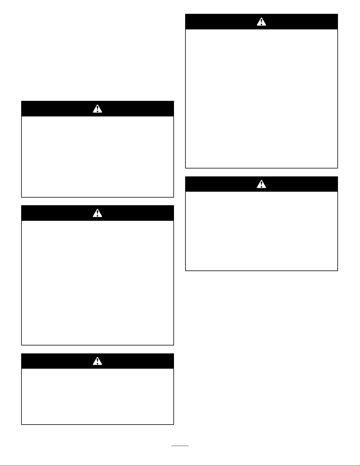
Theremaybeburiedpower,gas,and/or
telephonelinesintheworkarea.Shockor
explosionmayoccurifyoudigintothem.
Havethepropertyorworkareamarkedfor
buriedlinesanddonotdiginmarkedareas.
Contactyourlocalmarkingserviceorutility
companytohavethepropertymarked(for
example,intheUnitedStates,call811forthe
nationwidemarkingservice).
Rotatingrodandbitscanentangleloose
clothing,hands,arms,legs,andfeet,causing
deathorseriousinjury.
•Keepatleasttenfeetfromrotatingparts,
unlessyouareoperatingtherodguidetool.
•Neveruseanythingbuttherodguidetool
forstartingtherodandboringbit.
•Keepextremitiesandotherpartsofyour
bodyorclothingawayfromrotatingparts.
•Donotwearlooseclothingorjewelrywhile
operatingorassistingwiththeboringunit.
•Alwaysturnoffthetractionunitbefore
changingaccessories.
Whentheengineisoff,attachmentsinthe
raisedpositioncangraduallylower.Someone
nearbymaybepinnedorinjuredbythe
attachmentasitlowers.
Alwayslowertheattachmentlifteachtimeyou
shutoffthetractionunit.
Ifyoudonotfullyseattheattachmentlocking
pinsintheattachmentmountplateholes,the
attachmentcouldfalloffofthetractionunit
severelyinjuringtheoperatororbystanders.
•Ensurethatyoufullyseattheattachment
lockingpinsthroughtheholesinthe
attachmentmountplatebeforeliftingthe
attachment.
•Ensurethattheattachmentmountplateis
freeofanydirtordebristhatmayhinder
theconnectionofthetractionunittothe
attachment.
•Refertoyourtractionunit
Operator’ s
Man ual
fordetailedinformationonsafely
connectinganattachmenttoyourtraction
unit.
Hydrauliccouplers,hydrauliclines/valves,and
hydraulicuidmaybehotandcanburnyouif
youtouchthem.
•Weargloveswhenoperatingthehydraulic
couplers.
•Allowthetractionunittocoolbefore
touchinghydrauliccomponents.
•Donottouchhydraulicuidspills.
•Donotservicetheattachmentunlessrodrotationis
stopped,theauxiliaryhydraulicsleverismovedto
neutral,andtheengineofthetractionunitisstopped.
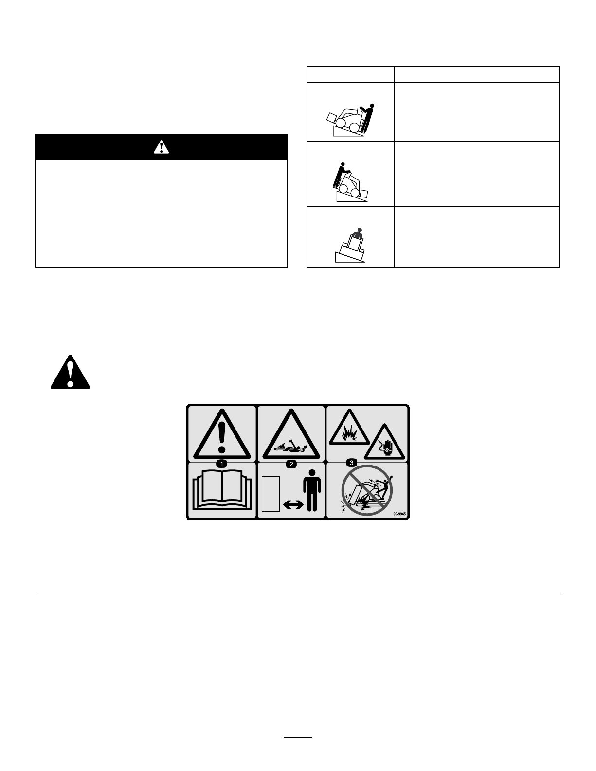
•Neveruseboltsorpinsinplaceofpushbutton
connectors.
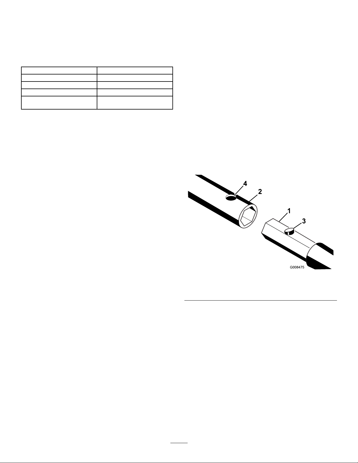
•Alwaysuse2peopletooperatetheattachment,one
tooperatethetractionunitandtheothertoguide
theboringunitwiththeguidetool.
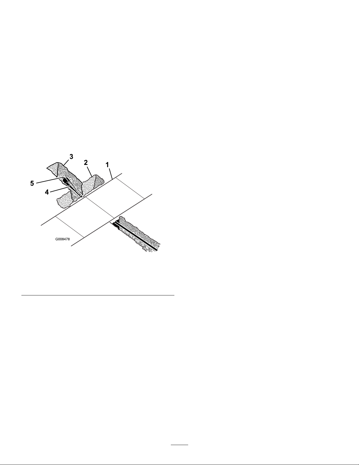
•Alwaysusetheguidetooltoaligntheboringunit.
•Neverstraddleorstandontherodwhentheengine
isrunning.
3