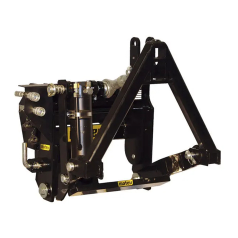
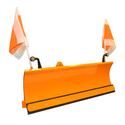
matev SRM-SF 140 Installation instructions

matev GmbH
Nürnberger Str. 50
90579 Langenzenn
T +49 (0) 9101 9087 -0
F +49 (0) 9101 9087 -20
info@matev.eu
www.matev.eu
Version
02/2014
Original Operating Manual
SRM-SF 140/ 160/ 180/ 200/ 220
Snow blade

Contents
Page 2
Table of contents
1About this operating manual....................................................................................3
2Safety.........................................................................................................................4
2.1 Intended use...............................................................................................................4
2.2 Qualifications of personnel..........................................................................................4
2.3 General safety instructions..........................................................................................4
2.4 Special safety notices .................................................................................................4
3Installation.................................................................................................................6
3.1 Attaching the snow blade on the tractor ......................................................................6
3.2 Adjusting the slide runners or casters .........................................................................7
3.3 Adjust the engagement angle of the blade..................................................................8
3.4 Adjust the pendulum compensation. .........................................................................10
3.5 Adjusting the pressure control valve..........................................................................11
4Operation and fault correction...............................................................................12
4.1 Operation..................................................................................................................12
4.2 Faults........................................................................................................................12
4.3 Contact.....................................................................................................................12
5Maintenance............................................................................................................14
5.1 Daily maintenance ....................................................................................................14
5.2 Maintenance after 50 operating hours or after a longer standstill period....................14
6Disposal...................................................................................................................16
7Guarantee................................................................................................................16
8Technical data.........................................................................................................16
9Wear parts and accessories...................................................................................17
10 List of illustrations..................................................................................................18
11 EC Declaration of Conformity ................................................................................19

Safety
Page 3
1 About this operating manual
Dear customer! Dear customer!
Thank you for purchasing this implement, we appreciate your trust.
Prior to using this implement for the first time, read this operating manual carefully and
conscientiously all the way through.
Keep this operating manual where it is easily accessible. This will enable you to refer to
important information and handling instructions as needed.
Listings with bullet points are marked as follows:
Text
Text
Text . . .
Handling instructions are marked in the sequence in which they should be executed, as
follows:
1. Text
2. Text
3. Text . . .
This implement is subject to change in the interest of technical progress. All
information, illustrations, and technical specifications represent the latest
status at the time this manual was published. The manufacturer reserves the
right to make changes at any time in the interest of technical progress.

Safety
Page 4
2 Safety
Guidelines and instructions with which you must comply, are summarized in this section.
Personnel who mount, operate and maintain this implement, must have read and under-
stood this operating manual.
2.1 Intended use
The snow blade is an implement for winter service and is used for clearing snow from
roads, paths, and other areas.
All other uses are excluded.
Non-intended use causes:
Danger of injury to the operator or third parties
Damage to the tractor and the implements
Environmental damage
2.2 Qualifications of personnel
Only personnel 18 years of age or older, or instructed personnel should install, operate,
and maintain the snow blade. The operator must have read and understood this operat-
ing manual.
2.3 General safety instructions
General safety instructions are explained in this section. These safety instructions are
used in the subsequent chapters. In addition to the safety aspect, you will save money
and work time if you follow these safety instructions.
Danger!
Severe injury to the operator or third parties occurs.
Comply with the safety instruction.
Attention!
Minor injury to the operator or third parties
can occur. The tractor, the snow blade or the environment can be damaged.
Comply with the safety instruction.
Note!
Important, helpful tips or information for the operator.
Read this note. It facilitates your work.
2.4 Special safety notices
Safety notices are specified in this section that are also affixed as stickers on the imple-
ment.

Safety
Page 5
Attention!
Prior to start-up read and comply with the operating manual and the safety
instructions.
Attention!
Prior to performing maintenance and repair tasks, turn off the engine and re-
move the key.
Attention!
Injuries due to fluid escaping under high pressure.
Comply with the instruction in the operating manual.
Attention!
Danger of crushing due to moving parts.
Never reach into the crushing hazard danger zone, if parts are still moving or
can move.
Comply with the instruction in the operating manual.

Installation
Page 6
3 Installation
Attention!
Before starting up the implement, read the instructions on safety and han-
dling for operation of the entire implement and connection to the tractor.
Danger!
Switch off the tractor and remove the ignition key before mounting or dis-
mounting the implements.
Note!
Enter the chassis number of the implement in section 4.3 of this operating
manual.
3.1 Attaching the snow blade on the tractor
In order to attach the snow blade to a tractor, the tractor must be equipped with a front lift.
Take up via a coupling triangle is described in more detail below:
1. Position the snow blade in such a manner that you can drive to just in front of its
coupling triangle.
2. Then the coupling triangle of the front lift is lowered all the way and is brought under
the triangle of the snow blade by driving the tractor forward. In this process, ensure
that the coupling triangle of the front lift is tilted slightly forward. If it is not possible to
easily drive forward under the triangle of the snow blade, then the height can be set
suitably by adjusting the coupling triangle. To do this you must remove the 6 screws
and shift the coupling triangle up or down on the attachment flange. The final step is
to retighten the threaded unions.
Fig. 1: Adjusting the coupling triangle
3. Lifting the front power system hooks-in its coupling triangle under the coupling trian-
gle of the snow blade.
Coupling triangle
Threaded union

Installation
Page 7
4. Insert the locking pin on the coupling triangle and secure it via the spring cotter pin. If
this is not possible then the locking part must be readjusted. To do this both nuts are
unscrewed, the locking part is adjusted, the bolt is inserted and then it is retightened.
Fig. 2: Locking pin on the coupling triangle
5. Fit the hydraulic hoses, for the angle adjustment of the snow blade onto the coupling
sockets of the supplemental hydraulic system.
Fig. 3: Connecting the hydraulic lines on the tractor hydraulic system
3.2 Adjusting the slide runners or casters
Before starting to clear snow, the slide runners or the casters must be correctly adjusted.
To do this the snow blade is lowered onto a level surface via the hydraulic system. The
snow blade is correctly adjusted when the slide runners rest on the ground and the
scraper bar just barely touches the ground or clears the ground by 1-2 mm. If this is not
the case the snow blade must first be adjusted.
1. Lower the snow blade until it is just a little above the ground.
2. Set the hydraulic system to the float position and switch off the tractor.
3. Unscrew the clamp screws and lower the slide runners to the ground. For the variant
with casters, crank the casters downward until they rest full-surface on the ground.
Locking pin
Spring cotter pin
Nut
Hydraulic couplings

Installation
Page 8
Fig. 4: Adjust slide runner
4. Secure slide runners with clamp screws. For the variant with casters, engage the
lock bracket on the crank.
Fig. 5: Secure slide runner
Fig. 6: Secure telescopic foot
3.3 Adjust the engagement angle of the blade
Clamp screw
with lock nut
Slide runner
1-2 mm
Bracket

Installation
Page 9
The contact angle of the scraper bar on the ground influences the snow clearing capacity
of the blade. A lesser angle results in a more aggressive clearing capacity and the spring
flap, folds with slightly more resistance. With a greater angle the spring flaps fold at light-
er resistance and the blade runs more quietly.
Note!
The blade plate must be removed to adjust the contact angle.
1. Removing the blade plate
2. Unscrew the 8 fastening screws
Fig. 7: Fastening screws - attachment bracket
3. Adjust the length of the set screw.
Fig. 8: Adjust the length of contact angle - set screw
4. Retighten the 8 fastening screws, see Fig. 7.
Note!
To avoid premature wear, do not forget to tighten the fastening screws be-
fore using the blade again.
5. Mount the blade plate.
Set screw
Fastening screws

Installation
Page 10
3.4 Adjust the pendulum compensation.
To ensure the horizontal position of the blade in lifted position, the pendulum compensa-
tion springs are attached. The springs are preset in the factory and should only be read-
justed as required, i.e. if the blade does not hang horizontally in lifted position.
1. Lift out the snow blade.
2. Tension the springs by turning the laterally attached screws. Only tension the
springs that are opposite of the side on which the blade hangs down.
Fig. 9: Adjusting the pendulum compensation
Note!
The pendulum compensation element must be easy to move. Ensure that
the stop nuts on the pendulum compensation allow slight play of approx. 0.5
mm between pendulum plate and pivot bracket.
Pendulum compensation
springs
Inner - pressure piece
Screw

Installation
Page 11
Fig. 10: Pendulum plate
3.5 Adjusting the pressure control valve
If the snow blade is equipped with a pressure control valve the blade can give way when
moving laterally against obstructions, e.g. house walls or curbstones. The pressure at
which the blade gives way can be adjusted separately for each pivot direction. Unscrew
lock nut, use an Allen wrench to adjust set screw, retighten lock nut. Repeat the adjust-
ment on the opposite side of the pressure control valve for the other pivot direction. Turn
the set screw to the right to increase the pressure or to the left to decrease the pressure.
Fig. 11: Adjust the pressure control valve.
Stop nuts
Pivot bracket
Play approx. 0.5 mm
Pendulum plate
Lock nut
Set screw

Operation and fault correction
Page 12
4 Operation and fault correction
4.1 Operation
If the snow blade is correctly adjusted, you can start working. For travel between imple-
mentation sites the snow blade is lifted via the front lift and the lowering safeguard of the
front lift is activated. To work with the snow blade, it must be lowered into float position.
Danger!
Driving on pressure is prohibited. This can make the vehicle unsteerable!
Attention!
A disabled hydraulic system can result in damage to the implement and/or
tractor!
To clear the snow to a specific side the snow blade can be pivoted via the hydraulic angle
adjustment. This setting must be made in a slightly lifted out position without load on the
snow blade. When working with the snow blade small unseen obstacles can be run over.
To protect the operator and the implement, the snow blade is equipped with spring-flap
segments. When encountering an obstacle (e.g. manhole cover) the spring-flap fold back
and the impact is reduced.
4.2 Faults
Fault:
Possible cause:
After clearing, snow still remains
Slide runner or support wheel is set too low, see 3.2
The snow blade vibrates excessively
when removing snow
Slide runner or support wheel is set too high, see 3.2
extremely uneven substrate
Tractor is hard to steer
Hydraulic system for the front lift is not in float position
The snow blade oscillates back and
forth when clearing snow
Hydraulic system for angle adjustment is not in float posi-
tion
bearings are deflected
Pendulum compensation element
moves with great difficulty
Stop nuts of the pendulum compensation element over-
tightened, see 3.4
4.3 Contact
If there are faults, problems, or other indications of malfunction,
contact your sales consultant or directly contact the manufacturer.
Enter the article number and the chassis number here.
This information is on the type plate of the implement.
Code - number:....................................................................
Serial number:......................................................................

Operation and fault correction
Page 13
Fig. 12: Nameplate

Maintenance
Page 14
5 Maintenance
The entire implement must be subjected to regular service.
After first use, the threaded unions on the snow blade must be checked and retightened if
necessary. Particularly check the following components:
Blade plate
Blade extensions
Flap-segments
Scraper bars
Attachment bracket
Holder of the slide runners, or telescopic foot
Mechanism of the contact angle.
5.1 Daily maintenance
Check scraper bars for wear
Check adjustment of the slide runners or the casters
Check pendulum compensation for ease of movement
Check hydraulic connections and lines
Clean the implement.
Danger!
Hydraulic oil escaping under high pressure can penetrate under the skin
and cause severe injuries. Never attempt to find a possible leak point on the
hydraulic lines by feeling them with your hands.
5.2 Maintenance after 50 operating hours or after a longer standstill period.
At regular intervals, and always at the beginning and end of the season, the moving parts
of the implement must be checked and if necessary the threaded unions must be retight-
ened. The scraper bars must be checked for wear.
Lubricate the points cited below with grease (not with oil):
Fig. 13: Lubricating nipple - cylinder eyes
Lubricating
nipples

Maintenance
Page 15
Fig. 14: Lubricating nipple - piston rod eye
Fig. 15: Lubricating nipple - pendulum axle
Fig. 16: Swing axle of the snow blade
Lubricating
nipples
Pendulum axle
Lubricating nipp-
les
Lubricating nipple - swing axle

Maintenance
Page 16
6 Disposal
The snow blade must be disposed of in accordance with the applicable regulations of the
municipality or the country. Take the parts to the collection points for residual waste, spe-
cial waste, or recycle them depending on material.
matev GmbH does not provide any disposal services.
7 Guarantee
The general delivery conditions of matev GmbH apply.
8 Technical data
Technical data
(without accessories)
SRM-SF 140
SRM-SF 160
SRM-SF 180
SRM-SF 200
SRM-SF 220
Working width, max.
1.4 m
1.6 m
1.8 m
2.0 m
2.2 m
Working width, angled
1,212 mm
1,382 mm
1,555 mm
1,726 mm
1898 mm
Weight
188 kg
209 kg
242 kg
264 kg
277 kg
Blade height
610 mm
610 mm
750 mm
750 mm
750 mm
Angle adjustment
30,3°
30,3°
30,3°
30,3°
30,3°
Length
580 mm
580 mm
700 mm
700 mm
700 mm

Maintenance
Page 17
9 Wear parts and accessories
Wear parts and accessories
SRM-ST/IX 140-220 attachment cat. 0
SRM-ST/IX 140-220 attachment cat. 1
SRM-ST/IX 140-220 attachment cat. 1 for quick-catch hook
SRM-ST/IX 140-220 attachment Scanframe
Rubber scraper bar kit 140 cm
Rubber scraper bar kit 160 cm
Rubber scraper bar kit 180 cm
Rubber scraper bar kit 200 cm
Rubber scraper bar kit 220 cm
PU scraper bar kit 140 cm
PU scraper bar kit 160 cm
PU scraper bar kit 180 cm
PU scraper bar kit 200 cm
PU scraper bar kit 220 cm
Side end plates, kit
Casters, kit
Pressure control valve kit
Bumper, kit
Holder for warning flags and side marker lights
Warning flags, kit
Warning flags plastic, kit
Side marker lights, kit
Side marker lights LED, kit

List of illustrations
Page 18
10 List of illustrations
Fig. 1: Adjusting the coupling triangle.......................................................................................................6
Fig. 2: Locking pin on the coupling triangle...............................................................................................7
Fig. 3: Connecting the hydraulic lines on the tractor hydraulic system.......................................................7
Fig. 4: Adjust slide runner.........................................................................................................................8
Fig. 5: Secure slide runner.......................................................................................................................8
Fig. 6: Secure telescopic foot...................................................................................................................8
Fig. 7: Fastening screws - attachment bracket..........................................................................................9
Fig. 8: Adjust the length of contact angle - set screw................................................................................9
Fig. 9: Adjusting the pendulum compensation ........................................................................................10
Fig. 10: Pendulum plate.........................................................................................................................11
Fig. 11: Adjust the pressure control valve...............................................................................................11
Fig. 12: Nameplate.................................................................................................................................13
Fig. 13: Lubricating nipple - cylinder eyes...............................................................................................14
Fig. 14: Lubricating nipple - piston rod eye.............................................................................................15
Fig. 15: Lubricating nipple - pendulum axle ............................................................................................15
Fig. 16: Swing axle of the snow blade ....................................................................................................15

EC Declaration of Conformity
Page 19
11 EC Declaration of Conformity
EC Declaration of Conformity for a machine to confirm compliance with the Machinery Directive
2006/42/EC and with the statutory regulations issued for the implementation of the Machinery Directive.
The manufacturer matev GmbH
Nürnberger Str. 50
90579Langenzenn
declares that the machines with type designations:
SRM-SF -140 ST snow blade : Order number 131 7747
SRM-SF 140 IX snow blade : Order number 131 7748
SRM-SF 160 ST snow blade : Order number 131 7749
SRM-SF 160 IX snow blade : Order number 131 7750
SRM-SF 180 ST snow blade : Order number 131 7751
SRM-SF 180 IX snow blade : Order number 131 7752
SRM-SF 200 ST snow blade : Order number 131 7753
SRM-SF 200 IX snow blade : Order number 131 7754
SRM-SF 220 ST snow blade : Order number 131 7755
SRM-SF 220 IX snow blade : Order number 131 7756
comply with the provisions of the Machinery Directive 2006/42/EC and with the implementing national
statutory regulations.
The signer is authorized to compile the technical documents.
The address is the address of the manufacturer.
Date / Signature October 2013 ..........................................................
Name of signer Georg Hemmerlein
Signer information Managing Director
This manual suits for next models
4
Table of contents
Other matev Tractor Accessories manuals

matev
matev SCA-130 User manual

matev
matev FPS JD-2036R User manual

matev
matev FPS-PTO JD 4020 Installation instructions

matev
matev FPS-FZW-Kioti CS 2520 User manual

matev
matev SRM-VP 130 Installation instructions

matev
matev FPS-LS J23/27 Installation instructions

matev
matev FPS-FKH-Kioti CX 2510 User manual

matev
matev FPS-FKH-NH Boomer 35 MJ 2021 User manual

matev
matev SRM-FB 130 Installation instructions

matev
matev FPS-FKH-Kioti CS 2520 User manual