KUHN AXERA-M User manual

OPERATOR’SMANUAL
AXERA-M
N° 95718 B.GB - 11.2003

DEAR OWNER,
In buying a KUHN machine you have chosen wisely. Into it have gone years of thought,
researchandimprovements.Youwillfind,ashavethousandsofownersallovertheworld,that
you have the best that engineering skill and actual field testing can produce. You have
purchased a dependable machine, but only by proper care and operation can you expect to
receive the performance and long service built into it.
This manual contains all the necessary information for you to receive full efficiency from your
machine.Theperformanceyougetfromthismachineislargelydependantuponhowwellyou
readandunderstandthismanualandapplythisknowledge.PleaseDONOTASSUMETHAT
YOU KNOW HOW TO OPERATE AND MAINTAIN YOUR MACHINE before reading this
manual carefully. KEEP THIS MANUAL AVAILABLE FOR REFERENCE.
YourKUHN dealerwillinstruct youonthegeneral operationofyourmachine. He isinterested
that you get the best performance possible and will be glad to answer any special questions
that may arise regarding the operation of the KUHN machine.
Your KUHN dealer can offer a complete line of genuine KUHN service parts.
These parts are manufactured and carefully inspected in the same factory that builds the
machine to assure high quality and accurate fitting of any necessary replacements.
When ordering service parts it is important that you indicate the type of machine concerned
and its serial number.
Forthisreasonpleasecompletethemodelidentificationplatediagrambelowwiththerequired
information. This will provide you with an easy reference for future service parts orders.
ABOUT IMPROVEMENTS
KUHN iscontinuallystriving to improveitsproducts and,therefore,reserves the righttomake
improvements or changes when it becomes practical to do so, without incurring any
obligations to make changes or additions to the equipment sold previously.
Copyright2003 KUHN S.A.

3
Contents Page
Correct use 4
Driving on public roads 4
Accident prevention and safety issues 5
Essential instructions for the hydraulic system 7
Warning and instruction decals 8
Warning and instruction decals on fertilizer spreader 8
1. Machine specifications 10
1.1 Technical specifications AXERA M range 10
1.2 Taking delivery of the fertilizer spreader 11
2. Preparation of the fertilizer spreader 12
2.1 Attaching to the tractor 12
2.2 Parking the fertilizer spreader 12
2.3 Fitting the Tele-Space pto shaft (spreader side) 13
2.4 Hydraulic control connection 16
2.4.1 Single acting two cylinder shutter control 16
2.4.2 Double acting two cylinder shutter control 16
2.5 Fitting and removing the spreading discs 17
3. Adjusting the spreader 19
3.1 Spreading charts 19
3.2 Setting the application rate 20
3.3 Adjusting the fertilizer output point 21
3.4 Adjustment as per spreading charts (normal spreading/boundary spreading
during normal spreading)
22
3.5 Adjustment as per spreading charts (late top dressing/boundary spreading
during late top dressing)
23
3.6 Boundary spreading with boundary spreading discs DG 68 - 72 (Optional
Equipment)
24
3.7 Boundary spreading limiter GSE 5 (Optional Equipment) 24
3.8 Setting disc vanes for fertilizers not listed in spreading charts 25
4. Calibration check 28
4.1 Calculating the mean application rate 28
4.2 Carrying out the calibration check 29
5. Removing unused fertilizer 30
6. Cleaning 30
7. Servicing 31
7.1 Servicing PTO shafts fitted with a slip clutch (Optional Equipment) 31
8. Lubrication chart 31
8.1 Gearbox oil (check / change) 32
9. Checking the balance of the metering slides 33
10 Gearbox position control 34
11. Valuable tips for precision spreading 35
12. Fault diagnosis 36
13. Optional Equipment 37
14. Warranty conditions 40

4
When the symbol "Attention" appears in the manual it means that the sa-
fety of the operator, assistant, bystander, or the normal operation of the
machine, could be in danger. It is essential that all safety instructions are
observed. It is vitally important to make sure that all users have the op-
portunity to read and thoroughly understand these instructions.
Correct use
The AXERA M fertilizer spreader is designed to spread dry, prilled and granular fer-
tilizer as well as seeds. Any other use is inappropriate and any defects arising there-
from will invalidate the manufacturer's warranty; any risk associated therewith is
borne entirely by the user. Correct use also entails the full compliance with all oper-
ating, maintenance and repair instructions issued by the manufacturer.
The spreader should only be used, maintained and repaired by persons who are fa-
miliar with the machine and who have received instructions with regard to potential
dangers.
All current appropriate accident prevention requirements and all other general recog-
nised safety, technological work-related and road traffic legislation must be ob-
served.
Any warranty claims against the manufacturer for damage resulting from unauthor-
ized alterations to the machine will be ruled invalid
Driving on public roads
When driving on public roads and paths, ensure that the tractor/spreader combination
complies with all relevant road traffic regulations. (Overall permissible weight, over-
all permissible axle weight, lighting warning signs, guarding, etc.)
Attention: Pay attention to correct front axle weight!

5
Accident prevention and safety issues
Most accidents happen because someone ignores the most elementary safety rules
during operation, maintenance or transport. It is vital that all persons coming in con-
tact with the machine - the purchaser himself/herself, a member of his/her family, an
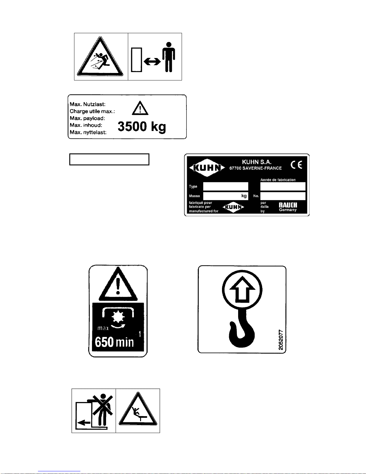
employee, a bystander - strictly obeys the following main safety rules. Other safety
instructions are to be found on the decals placed in various prominent positions on
the machine.
♦ Observe all safety notes contained in this Operators Manual and all current statu-
tory safety and accident prevention regulations!
♦ Before every operation, check nuts and bolts and other fixings for tightness, espe-
cially those of the spreading discs and spreading vanes. If necessary, tighten to re-
commended torque settings.
♦ Before using the machine, operators must familiarize themselves with all parts of
the equipment and the function of all controls and adjustments. Finding out dur-
ing operation may be too late.
♦ Before every operation, ensure that the tractor spreader combination complies with
all relevant road traffic, as well as health and safety regulations.
♦ When filling the hopper, lower the spreader to the ground and switch off the trac-
tor engine. Remove ignition key before leaving the tractor cab. Make sure shutter
controls are closed.
♦ Before adjusting or undertaking other work such as cleaning, lubricating or carry-
ing out operations on the spreader, disengage the PTO, switch off the tractor en-
gine, wait until all moving parts have come to a stop and remove the ignition key.
During control or repair work, make sure no one can switch on the unit by mis-
take.
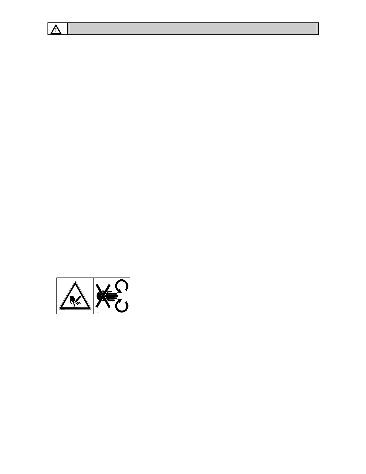
DANGER = Power driven parts !
Never put hands, feet or clothing anywhere near mov-
ing parts. Never reach into the hopper - moving parts !
Always avoid wearing loose clothing or clothing with
loose parts that are liable to come into contact with
moving parts.
♦ Keep the hopper free of any foreign bodies.
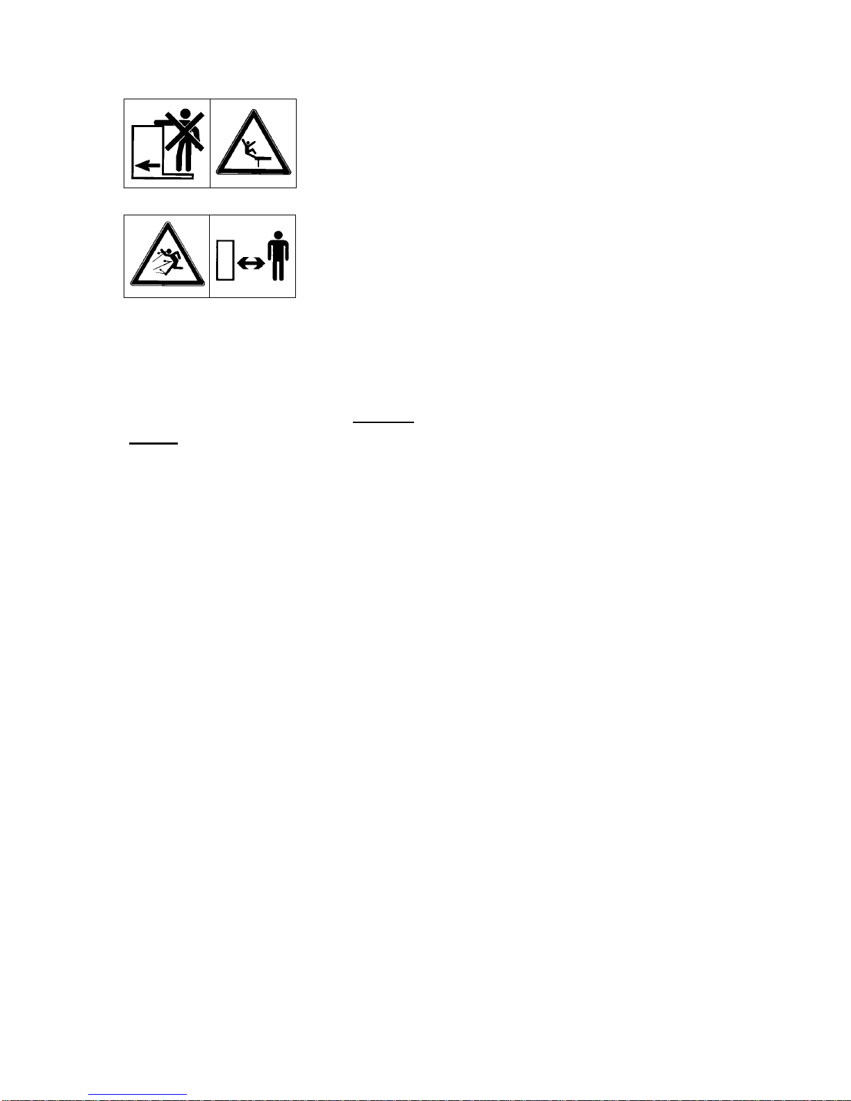
♦ Before starting the spreader, make sure that nobody is within the danger area a-
round the machine. Make sure you have a good view all round and keep a special
watch out for children!
♦ When outside the area of work the spreading mechanism must be disengaged.
♦ Only start up the spreader when all safety devices and guards have been properly
fitted.

6
♦ Never leave the spreader running unattended.
It is illegal and dangerous to carry passengers when using
or transporting the spreader.
Attention: ! Danger from revolving discs and fast mov-
ing spreading material. Make sure no one is within the
spreading zone around the spreader before engaging
the PTO shaft/spreading discs!
♦ Before leaving the tractor seat, lower the spreader on to the ground, switch the
tractor off and remove the ignition key. With single acting hydraulic shutter con-
trols, switch off the hydraulic hose shut-off valves.
♦ Parking the fertilizer spreader without being attached to the tractor : only with an
empty hopper and on firm, level ground.
♦ Never allow anyone to enter the space between tractor and spreader without first
making sure that the tractor is prevented from moving by means of a parking brake
and/or wheel chocks.
♦ It is absolutely forbidden to remain between tractor and fertilizer spreader during
operation
♦ Before attaching or removing the spreader from the tractor 3-point linkage, make
sure that the control valve is positioned so that inadvertent lowering or raising of
the linkage is impossible.
♦ It is recommended that the condition of the spreader is checked by a recognised
dealer at the end of every season. Especially disc vanes and fixings.
♦ In the event of a failure during operation, switch off the spreader immediately.
Stop engine and remove the ignition key before checking and repairing the dam-
age.
♦ PTO shaft and shaft protection damage must be repaired immediately before using
the spreader. WARNING: Power driven parts : this is a danger zone which can
cut or crush.
♦ Ill advised choice or use of fertilizer or other spreading material can cause serious
damage to people, animals, plants and the environment. Choose the correct mate-
rial for your application. Handle with car and carefully follow the manufacturer's
instructions.

7
Warning
Maximum attachment height of the fertil-
iser spreader!
Danger of injury by unintentional contact
with the spreading discs.
As protection against unintentional con-
tact with the discs, the maximum attach-
ment height of 1500 mm from the un-
derside of the guardrail to ground le-
vel must not be exceeded.
If this attachment height is insufficient
when in normal spreading mode, the late
top dressing mode position (attachment
height 0/ 6) should be used.
Essential safety instructions for the hydraulic system
♦ Hydraulic circuits contain oil under high pressure.
♦ Mark all hydraulic connections between tractor and implement at both coupling
sockets and plugs in order to avoid incorrect connection.
♦ Follow correct connecting instructions of hydraulic cylinder and motors. Inter-
changed hoses could cause the opposite effect to that expected.
♦ When connecting the hoses to the tractor, ensure that the hydraulic pressure in
both tractor and spreader has been relieved.
♦ Use suitable protection when locating leaks (safety goggles, gloves, etc.) in order
to avoid injury. Hydraulic fluid escaping under high pressure can penetrate the
skin and cause serious injuries! In case of injury, immediately consult a doctor, as
there is serious risk of infection.
♦ Before working on the hydraulic system, lower the fertilizer spreader on to the
ground, relieve the system pressure, switch off the engine and remove the ignition
key.
♦ Prior to coupling or uncoupling fittings, carefully clean all hydraulic connections.
♦ Operational time limit of a hydraulic hose line is six years from the date of manu-
facture. The manufacturing date of a hose is indicated in month and year on the
hose armature.
♦ The useful life of an undamaged hose should be limited to six years, including a
possible maximum two-year stocking period.
♦ Even when carefully stored and correctly used, hoses and hose connections un-
dergo natural aging. Therefore, their stocking and operational periods should not
be exceeded.
♦ Replacement hoses must meet the technical specifications quoted by the spreader
manufacturer.
Ground

8
Warning and instruction decals
Warning and instruction decals give important information to operate the fertilizer
spreader without danger.
♦ Replace any decals that are missing or illegible.
♦ Further decals are available from the spare parts department of your dealer or di-
rect from the factory.
♦ Before placing new decals on the fertilizer spreader, remove all dust, dirt and
grease and thoroughly dry the area where the decal is placed.
♦ Correct decals must be placed on any replacements fitted to the machine during
maintenance or repair work.
Warning and instruction decals on the fertilizer spreader
The fertilizer spreader carries the following warning and instruction decals which gi-
ve important information for your safety and the safety of others. They also contain
information on correct operation. The text by each diagram explains the message that
the decal is giving.
c
Before starting the machine, read the
Operators Manual and safety instruc-
tions carefully.

9
d
Danger from revolving discs and fast
moving spreading material. Make sure
no one is within the spreading zone be-
fore switching on the PTO
drive/spreading discs !
e
Maximum payload.
f
Machine No.
(Stamped on frame)
g
(Serial number plate)
h
(PTO speed)
i
(Hooking point when loading
e.g. with a crane.)
It is illegal and dangerous to car-
ry any passenger on the fertiliser
spreader

10
1. Machine specifications
Manufacturer
RAUCH Landmaschinenfabrik GmbH
Landstraße 14 Postfach 1162
D-76547 Sinzheim D-76545 Sinzheim
1.1 Technical specifications AXERA M range
Technical
Specifications
AXERA M
Capacity approx. l 1100
Payload max. kg 3500
Filling height approx. cm 99
Filling width approx. cm 240
Hopper size approx. cm 250x115
Weight approx. kg 430
Working width m 12 - 42 m depending on fertilizer type and vanes
Noise level 70 db (A) (Depending on fertilizer type and application rate)
Empty weight data is given on the fertiliser spreader serial number plate
The weight of the fertiliser spreader (mass) when empty varies according to the equipment fitted.
The weight indicated on the serial number plate applies to the most commonly used specifica-
tion. It can, however, be higher or lower.
Type / combination Capacity
(+ litres)
Max. extension
size (cm)
Filling height
(+ cm)
Description Extension
weight (kg)
B 413 + 400 l 250x115 + 0 3- sided 25
B 713 + 700 l 250x115 + 10 3- sided 50
B 910 + 900 l 250x115 + 30 4- sided 50
B 1210 + 1200 l 250x115 + 42 4- sided 70
B 910 + B 413 + 1300 l 250x115 + 30 4+3- sided 75
B 910 + B 713 + 1600 l 250x115 + 40 4+3- sided 100
B 910 + B 910 + 1800 l 250x115 + 60 4+4- sided 100
B 1210 + B 713 + 1900 l 250x115 + 52 4+3- sided 120
B 1210 + B 910 + 2100 l 250x115 + 72 4+4- sided 120
GLB 903 + 900 l 280x115 + 15 3- sided 60
GLB 1000 + 1000 l 280x115 + 30 4- sided 65
GLB 1400 + 1400 l 280x115 + 43 4- sided 80
GLB 1000 + GL 700 + 1700 l 280x115 + 52 4+4- sided 110
GLB 1400 + GL 700 + 2100 l 280x115 + 65 4+4- sided 125
ATTENTION

11
1.2 Taking delivery of the fertilizer spreader
When the fertilizer spreader is delivered, please check that it is complete.
The following items are included as standard equipment:
;Calibration kit (slide rule calculator)
;Top and bottom 3-point linkage pins
;Set of spreading discs (according to choice)
;PTO shaft (including PTO instruction book)
Also carefully check all ordered optional equipment.
Attention : Check all nuts and bolts and other fixings for tightness, es-
pecially those of the spreading discs and spreading vanes.
Right-hand disc (R) and left-hand disc (L) must be correctly mounted on
their respective sides when viewing the machine in direction of travel.
Discs and vanes are indicated with (R) or (L).
Claims can only be accepted if notified at time of delivery. Ask the haulier to ac-
knowledge any transport damage. In case of doubt, contact your dealer or the factory
direct.

12
2. Preparation of the fertilizer spreader
Take special care when attaching/detaching the fertilizer spreader
to/from the tractor.
2.1 Attaching to the tractor
The fertilizer spreader AXERA M can be attached to Cat.II tractor linkages. At-
tachment to Cat.III tractor linkages is only possible using Cat.II geometry and plac-
ing reduction sleeves over upper and lower linkage pins. A second lower link con-
nection is provided as standard and allows a higher attachment height to the tractor
of approx. 140mm. The upper and lower pins must be secured in place with the
linchpins attached to the spreader.
For correct horizontal spreading of fertilizer, the fertilizer spreader must be attached
as per dimensions given in the spreading charts.
Pay attention that the spreader is mounted at right angles to the direction of travel, is
perfectly horizontal and that the 3-point frame is correctly restrained from sideways
movement to avoid the unit swinging from side to side during operation.
Important: If the lower link pins are in the upper connection point then the top
link pin must also be placed in its upper connection point, to avoid poor load dis-
tribution between upper and lower links.
2.2 Parking the fertilizer spreader
The spreader can be parked on the frame, support rollers or parking stand (support
rollers & parking stand are optional equipment).
When parking the spreader pay attention to the following :
♦ When operating the external tractor 3-point lift control lever, do not stand between
the tractor and the spreader.
♦ Before uncoupling the spreader from the tractor make sure that all weight from the
upper and lower linkage coupling points is relieved.
♦ Only park the spreader when the hopper is empty and on a firm level surface.
♦ After disconnecting PTO shaft and hydraulic hoses from the tractor, place them in
the holders provided on the spreader.

13
2.3 Fitting the Tele-Space pto shaft (spreader side)
Only pto shafts supplied or recommended by the manufacturer should be used. The
fertiliser spreader is equipped with a pto shaft that corresponds to the implement's
technical characteristics and power requirements. It should not be replaced with
shafts with other specifications.
When first attaching the spreader to the tractor, the length of the shaft must be
matched and, if necessary, shortened to fit the tractor correctly.
Read the pto manufacturer's operator's manual carefully, taking special note of the
instructions concerning the shortening of the shaft. This operator's manual can be
found attached to the pto shaft.
If the pto shaft is too long, both pto drive and the spreader may be damaged when the
unit is raised.
The Tele-space pto shaft allows additional free room for easy coupling of the fertil-
iser spreader to the tractor.
DANGER
Fitting and removing the pto shaft (fertiliser spreader side)
Injury or death hazard due to rotating shaft.
• Before fitting or removing the pto shaft, make sure that the cou-
pled spreader is secured by support blocks to avoid unintentional
lowering and that the tractor is choked to avoid unintentional
creeping.
• Before fitting or removing the pto shaft, make sure that the pto
drive is disengaged, the tractor engine is switched off and the ig-
nition key is removed!
• Always respect correct fitting and securing of the pto shaft. The end marked with
a tractor symbol must be fitted on the tractor side.
Remove the cover (1) from the bell protector
guard.
Fit the pto shaft onto the drive stub and secure in
place with the hexagon nut and bolt (2) and (3).

14
Refit the cover (1) into its original place.
• Make sure that pto shafts, protector tube and end gaiter, as well as extension gai-
ters on the fertiliser spreader side, are correctly in place and in good condition!
• Do not use the safety chain to support the shaft when not in use.
• Before engaging the pto drive, make sure that the correct tractor pto speed is se-
lected to match the implement.
• When detaching the pto drive shaft, place in the holder provided on the fertiliser
spreader.
IMPORTANT
Drive shaft damage when engaging the pto drive
The pto drive shaft and the agitator drive can suffer damage if the
pto drive is engaged at high tractor engine speeds.
• Engage the pto drive at lower tractor engine speeds to avoid
sudden overload to the drive shaft and agitator drive.
• With abrupt engaging on hydraulic tractor pto drives, it is rec-
ommended that a pto incorporating a friction clutch is used.
Additional information for the fitting of pto shafts equipped with a friction
clutch (optional equipment).
WARNING
Friction clutch injury hazard
Pto drive shafts with friction clutches not conforming to recognised
standards can cause serious injury.
• The friction clutch must always be installed on the spreader si-
de.
• For safety reasons an additional extension guard must be fitted
to the spreader side when using a pto drive shaft equipped with
a friction clutch.
• Should a pto shaft with friction clutch be fitted after the ma-
chine has been delivered, the extension guard included with the
shaft must be fitted onto the spreader.
• It is recommended that the friction clutch be checked by a pro-
fessional workshop for correct functioning at the end of each
season.

15
ASSEMBLY
• Fit the friction clutch extension guard to the spreader side.
• Slide the friction clutch end of the pto shaft onto the spreader
and bolt in place.
ATTENTION
Checking the friction clutch locking bolt for correct tightness
• The locking bolt should be checked regularly for tightness!
• Read the manufacturer's additional maintenance instructions
delivered with the friction clutch!

16
2.4 Hydraulic control connection
Each shutter control mechanism is separately operated by two individual hydraulic
cylinders. After disconnecting the fertilizer spreader from the tractor, the dust caps
should be refitted in the hydraulic connections and, to avoid dirt contamination, the
hydraulic hoses must be placed in the holders provided on the spreader.
Important: Before every operation, check to ensure that both open/close shutter sli-
des fully open and fully close.
2.4.1 Single acting two cylinder hydraulic shutter control
Oil pressure closes - Spring pressure opens
Tractors must be equipped with two hydraulic valves.
With optional extra double acting equipped units only one one control valve is
needed.
Prior to long transport journeys, or when filling, the hydraulic hose shut-off valves
must be closed, thus preventing subsequent opening of the shutter slides, should oil
inadvertently escape through the control valves.
By closing either the left- or the right-hand open/close shutter slide, the unit can be
operated to spread to one side only, thus avoiding double spreading or overspreading
in narrow field areas or on field edges and neighbouring fields.
If the empty spreader is uncoupled from the tractor, the open/close shutter slides
must be left open so that spring tension is not weakened.
2.4.2 Double acting two cylinder hydraulic shutter control
Oil pressure closes and opens
Tractors must be equipped with two hydraulic valves. By closing either the left- or
right-hand open/close shutter slides, the unit can be operated to spread to one side
only, thus avoiding double spreading or overspreading in narrow field areas or on
field edges and neighbouring fields.

17
2.5 Fitting and removing the spreading discs
Depending on the fertilizer type and working width, different spreading discs can be
used. Spreading disc type is listed in the spreading charts. To simplify changing the
spreading discs it is recommended to slide the movable gearbox to the rear and lock
in place (see Photo 1). Using a screwdriver or ∅8 mm round bar, loosen the syn-
thetic disc hub nuts (Photo 1, No. 1) and remove spreading discs.
Only fit and remove spreading discs when the PTO and tractor engine
are switched off and the ignition key has been removed.
Spreading discs are fast moving parts, therefore carry out any work with
great care and attention.
Replace any defective synthetic disc hub nuts (threads, splits, fractures)
immediately.
Photo 1
Note: When fitting the spreading discs on to the disc hub, make sure not to invert
the right-hand spreading disc (R) with the left-hand spreading disc (L)!
The right-hand disc (R) and left-hand disc (L) must be placed carefully over their
corresponding drive hubs when viewing in the direction of travel.
Centre the spreading disc on to the disc hub, making sure it is lying correctly.
Discs and vanes are indicated with (R) or (L).

18
♦ Make sure the synthetic disc hub nuts are correctly fitted (not cross-threaded)
(Photo 2; No.1).
♦ Tighten the synthetic disc hub nuts (Photo 2; No.1) by hand.
♦ Turn the spreading discs by hand to make sure discs and vanes (Photo 2; No.2)
turn freely without fouling the metering output tracts (Photo 2; No.3).
Photo 2
Important: After the first hour of operation, check that the synthetic disc hub nuts
(Photo 2; No.1) are firmly seated.

19
3. Adjusting the spreader
3.1 Spreading charts
Values provided in the spreading charts are derived from practical tests in the manu-
facturer's purpose built fertilizer spreader research centre. Settings are obtained using
fertilizer in perfect condition from each respective manufacturer.
Note: The mounting height is always measured from the top of the crop to the lo-
wer edge of the frame.
Mount the fertilizer spreader on to the tractor in accordance with the instructions and
measurements given in the spreading charts.
We would particularly emphasize that physical characteristics of fertilizers can vary,
even within the same type and brand, due to differences in size of granules, density,
surface texture, specific weight and quality of granules, etc.
These variations can influence spreading characteristics quite markedly, which re-
sults in differences in the fertilizer application rates as well as changes in spread pat-
terns predicted in the spreading charts, therefore, making it necessary to recalibrate
the fertilizer spreader.
The data provided in the spreading charts can only be used as a guideline. To ensure
greater accuracy, the unit should be recalibrated for application rate and spread pat-
tern every time fertilizer is changed, even when using different bags of the same fer-
tilizer.
We suggest the use of only quality fertilizer from well-known suppliers, preferably
those fertilizers listed in the spreading charts. If you need to use fertilizers not listed,
please contact us.
Note: Spreading of Urea: This highly concentrated nitrogen fertilizer has a wide
variation of quality and particle sizes, due to the great number of importers han-
dling this product. It is therefore essential to recalibrate the unit every time this
fertilizer is used. Also note that Urea is very susceptible to wind variations.
Pay special attention when setting the spreader. Even a very small error in setting can
result in a large change in spreading pattern.
We must stress that no liability can be accepted for consequential losses or damages
due to spreading errors.
Before adjusting, lubricating, cleaning or carrying out any operation
on the machine, disengage PTO drive, switch off the tractor engine,
wait until all moving parts have come to a stop and remove the igni-
tion key before leaving the tractor.

20
3.2 Setting the application rate
There are two shutter slides per hopper outlet. The open/close shutter slides (Photo 3,
No.5) only move hydraulically to a fully opened or a fully closed position.
Photo 3
The hand operated metering slides (Photo 4, No.6) control the application rate with
the aid of a fine graded flow rate quandrant (Photo 4, No.7) and indicator (Photo 4,
No.8). When the application rate is selected in accordance with the spreading
charts/calibration test, position the metering slides (Photo 4, No.6) in the same place
on both sides by firmly locking the handlock nut (Photo 4, No.9) in place.
Photo 4
Table of contents
Other KUHN Farm Equipment manuals