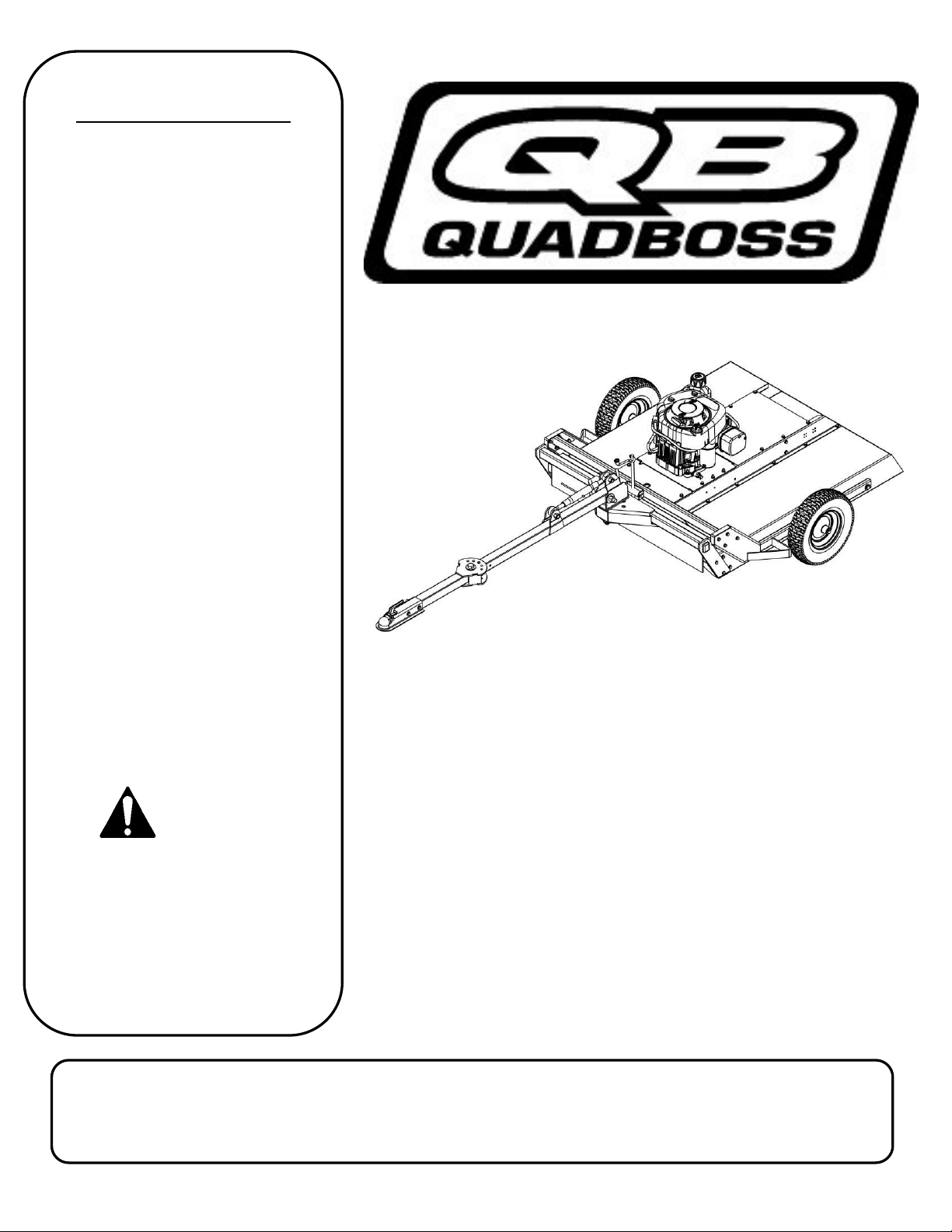
Swisher Quadboss L18-236001 Series User manual

8/23/2019
44” COUNTRY CUT
TRAIL CUTTER
OWNER’S
MANUAL
SWISHER ACQUISITION INC.
1602 CORPORATE DRIVE, WARRENSBURG, MISSOURI 640 3
PHONE (660) 747-8183 FAX (660) 747-8650
Assembly
Operation
Service and Adjustment
Repair Parts
www.swisherinc.com
MODEL NO.
STARTING SERIAL #:
L18-236001
QBRC11544
17341 REV 18-236
Read and follow all
Safety Precautions
and Instructions
before operating this
equipment.
IMPORTANT
Read and follow all
Safety Precautions
and Instructions
before operating this
equipment.
IMPORTANT
ade I The
USA
of US and Global Parts

LIMITED WARRANTY
The manufacturer’ warranty to the original con umer purcha er i : Thi product i free from
defect in material and workman hip for a period of one (1) year from the date of purcha e
by the original con umer purcha er.
We will repair or replace, at our di cretion, part found to be defective due to material or
workman hip. Thi warranty i ubject to the following limitation and exclu ion :
1) Engine Warranty All engine utilized on our product ha a eparate warranty
extended to them by the individual engine manufacturer. Any
engine ervice difficulty i the re pon ibility of the engine
manufacturer and in no way i Swi her or it agent re pon ible
for the engine warranty. The Brigg & Stratton Engine Service
Hot Line i 1-800-233-3723.
2) Commercial U e Thi product i not intended for commercial u e and carrie no
commercial warranty.
3) Limitation Thi warranty applie only to product , which have been
properly a embled, adju ted, and operated in accordance with
the in truction contained within thi manual. Thi warranty
doe not apply to any product of Swi her that ha been ubject
to alteration, mi u e, abu e, improper a embly or in tallation,
hipping damage, or to normal wear of the product.
4) Exclu ion Excluded from thi warranty are normal wear, normal
adju tment , and normal maintenance.
In the event you have a claim under thi warranty, you mu t return the product to an
authorized ervice dealer. All tran portation charge , damage, or lo incurred during
tran portation of part ubmitted for replacement or repair under thi warranty hall be borne
by the purcha er. Should you have any que tion concerning thi warranty, plea e contact u
toll-free at 1-800-222-8183. The model number, erial number, date of purcha e, and the
name of the authorized Swi her dealer from whom you purcha ed the mower will be needed
before any warranty claim can be proce ed.
THIS WARRANTY DOES NOT APPLY TO ANY INCIDENTAL OR CONSEQUENTIAL
DAMAGES AND ANY IMPLIED WARRANTIES ARE LIMITED TO THE SAME TIME
PERIODS STATED HEREIN FOR ALL EXPRESSED WARRANTIES. Some tate do not
allow the limitation of con equential damage or limitation on how long an implied warranty
may la t, o the above limitation or exclu ion may not apply to you. Thi warranty give
you pecific legal right and you may have other right , which vary from tate-to- tate. Thi i
a limited warranty a defined by the Magnu on-Mo Act of 1975.
2

SAFETY PRECAUTIONS
This Safety Alert Symbol indicates important messages in this
manual. When you see this symbol, carefully read the message that
follows and be alert to the possibility of personal injury.
Read this manual completely. This machine can amputate hands and feet, and
throw objects. Failure to observe the following safety instructions could result in
serious injury or death.
Thank you for choo ing Swi her’ 44” Trail Cutter. Before operating
your cutter, plea e read, under tand and follow all of the afety precaution
and other in truction explained in thi manual. A with all power
equipment, lawn mower and cutter can be potentially dangerou if
improperly u ed.
3
• Read the manual. Learn to operate thi machine afely.
• Alway di connect the park plug wire and place the wire where it cannot contact the
park plug, to prevent accidental tarting the engine when etting up, tran porting,
adju ting or making repair .
• Keep all hield and guard in place.
• Under tand the peed, teering and tability of thi machine. Know the po ition and
operation of all control before you operate thi machine. Check all of the control in
a afe area before tarting to work with thi machine.
• Allow only re pon ible adult who are familiar with the e in truction to operate thi
machine. Never allow children to operate this machine.
• Clear the area of object uch a rock , toy , wire, etc. that can be picked up and
thrown by the blade.
• Be ure the area i clear of other people before mowing. Be aware of the cutter
di charge direction and do not point at anyone. Stop the machine if anyone enter the
cutting area. Children are often attracted to the machine and the mowing activity.
Never assume that children will remain where you last saw them. Keep children
under the watchful care of another re pon ible adult.
•No riders!
• Do not put hand or feet near or under rotating part .
• Do not mow in rever e. Always look down and behind before and during backing.

• Turn off the blade when not cutting. Before leaving the machine, turn off the blade
and top the engine.
• Watch for traffic when operating near or cro ing roadway .
• Do not operate the cutter if it ha been dropped or damaged in any manner or if the
mower vibrate exce ively. Exce ive vibration i an indication of damage.
Repair cutter a nece ary.
• Dre properly. Do not operate the cutter when barefoot or wearing open andal .
Wear only olid hoe with good traction when cutting.
• Never allow operation by untrained per on .
• Do not operate the machine while under the influence of alcohol or drug .
• Do not operate on lope greater than 15 degree .
• Never tamper with afety device . Check their proper operation regularly.
• Stop and in pect the equipment if you trike an object. Repair, if nece ary, before
re tarting. Never make adju tment or repair with the engine running.
• Cutter blade are harp and can cut. Wrap the blade or wear glove , and u e extra
caution when ervicing them. Do not operate at too fa t a rate.
• Return lever to it vertical po ition to di engage blade .
• The braking y tem i applied when the blade become di engaged. It i de igned to
bring the blade to a quick top (approximately 7 econd ). Each Trail Cutter brake
y tem ha been et at the factory. For afety, the con umer hould not alter the
braking y tem.
4
ASSEMBLY
• In ert 5/8-11 X 2½ bolt through the top of the Pivot A embly and Top Link and ecure with
5/8-11 nut. In ert 5/8-11 x 2½ bolt through the tab on the top of the Hitch bar and Top Link and
ecure with 5/8-11 nut.
• Place 2” Hitch Coupler on the end of the Hitch Bar. Align Hole with Hitch Bar and Coupler.
Fa ten u ing (2) 3/8-11 x 3 Bolt , (4) 3/8 Wa her , and (2) 3/8-11 Locknut . Tighten nut
ecurely.
• The hitch can be adju ted up or down to level the deck from front to back. (See figure 2 page 11)
• Check engine oil. All engine are filled with oil at the factory. Verify oil level and
add if nece ary before tarting engine. (See Engine Owner’ Manual)
• Verify fuel level and add if nece ary before tarting engine.
• Reconnect park plug wire.
• Refer to Owner’ Manual pg 5 for proper operating procedure .
Wrench/Socket
Qty. Size
(1) 1-1/8”
(1) 1-1/16”
(2) 15/16”
(2) 9/16”
Tools Required:
• Di engage park plug wire and place where it cannot make a
connection.
•Refer to Fig. 1 pg. 11. Attach hitch a embly part to front of
mower u ing 3/8-16 X 1¼ bolt and ecure with 3/8-16 locknut .
In ert 3/4-10 x 4 ½” bolt through the bottom hole of the pivot
a embly, (2) 3/4 wa her , and hitch tube and ecure with 3/4-10
nut. Tighten nut tight until tube i clamped tight, then back off 1/4
turn to allow tube to pivot.

ӥ
5
OPERATING YOUR TRAIL CUTTER
The operation of any mower can produce foreign object to be thrown into the eye , re ulting in evere eye
damage. Alway wear certified afety gla e or wide-vi ion afety goggle over pectacle before tarting
any cutting machine and while operating uch a machine.
The operation of any mower produce ound wave that are damaging to the human ear. Ear protection i
recommended.
CAUTION! Tragic accident can occur if the operator i not alert to the pre ence of children.
Children are often attracted to the machine and the mowing activity. Never assume that children will
remain where you last saw them.
STOPPING THE ENGINE
• Make ure the tow vehicle parking brake i et.
• Di engage cutting blade .
• Reduce engine to idle peed and allow engine to run momentarily for cooling.
• Turn the key to the off po ition.
INTENDED USE
The 44” Trail Cutter i de igned to clear den e area of gra and cut apling up to 3” thick
on meadow and mall e tate . It is not intended to create a finish cut on lawns. Your
Trail Cutter hould be towed behind an ATV, golf cart, lawn tractor or other approved
vehicle. It i not recommended for peed exceeding 5 MPH.
ATTACHING TRAIL CUTTER TO TOW VEHICLE
• Back vehicle up to de ired towing po ition.
• Off et the Trail Cutter to the ide oppo ite the tow vehicle di charge (if any).
Thi prevent the tow vehicle from throwing gra into Trail Cutter engine.
• U ing the 7365 2” ball coupler, connect the hitch to the vehicle your machine
will be towed with. Once attached, adju t the cutting height and level the
mower by rotating the adju tment rod (See figure 2 page 11).
TRANSPORTING CUTTER
• Stop Trail Cutter.
• Place Trail Cutter deck in it highe t po ition.
• When tran porting without the u e of a tow vehicle, remove park plug wire
and place it where it cannot contact the park plug.

歐ӧ
6
ENGAGING BLADES
Note: Do not attempt to tart the unit with the T-handle con ole in the “ENGAGED” po ition.
• Engage blade by pulling down the T-handle lever into the horizontal po ition.
• Return lever to the vertical po ition to di engage blade . See Fig 10 pg 17.
• The braking y tem i applied when the blade become di engaged. It i de igned to bring
the blade to a quick top (approximately 7 econd ). Each Trail Cutter brake y tem ha
been et at the factory the con umer hould not alter any part of the brake y tem.
BREAKING IN YOUR CUTTER
• Set the vehicle parking brake and chock the wheel to prevent accidental rolling.
• While engine i running, engage the blade control.
• In a afe environment, (i.e. no children or pet ) allow the blade to rotate and the engine to
run at full throttle for 5 minute , breaking in the belt for longer life.
• Di engage the blade and hut off the engine.
CAUTION: SHUT OFF THE CUTTER ENGINE AND REMOVE SPARK
PLUG WIRE FROM SPARK PLUG BEFORE MAKING ANY
ADJUSTMENTS TO THE CUTTER.
STARTING THE ENGINE
See engine manufacturer’s recommendations for the type and amount of oil and fuel used.
• Make ure the tow vehicle parking brake i et, mower i level, and blade are di engaged.
Engine mu t be level to accurately check and fill oil. Do not overfill.
• Check park plug wire, oil, and fuel.
• Check all electrical connection for buildup of debri .
• Set engine idle to “CHOKE” po ition.
• Turn key to the “RUN” po ition.
• Pull rope with a ingle fluid motion.
• Set engine idle at maximum RPM for be t performance.
• Allow engine to run a few moment before engaging blade .
IMPORTANT: This engine is not equipped with a spark arrester muffler. It is a violation of
California Public esource Code Section 4442 to use or operate the engine on any forest-covered,
brush-covered, or grass-covered land. Other states or federal areas may have similar laws.

㹐Ө
7
CUTTER HEIGHT ADJUSTMENT
• There i approximately 4” of height adju tment.
• Rotate height adju t crank handle in a clockwi e direction to lower the mower deck.
Rotate counterclockwi e to lift the mower deck.
• Den e area hould be cut twice.
• Pu h handle down to lock height po ition.
• Adju t the top link located on the front of the hitch to level the mower after
adju ting the cutting height (See figure 2 page 11).
TOW HITCH OFFSET
• If towing with a lawn tractor, off et the rough cut mower to the oppo ite ide of the
lawn tractor gra di charge.
• Swi her recommend if the tow vehicle i equipped with a mid-mount mower to
overlap the cut approximately 6”. Thi may vary depending on mowing terrain,
ob tacle , and/or tow vehicle. Alway keep afety the fir t priority.
• Alway keep the tow vehicle cutter rai ed higher than the Trail Cutter.
STARTING TO CUT
• Adju t the cutting height.
• Double check tow vehicle to rough cut mower attachment.
• Start mower engine and et throttle to “FAST” for be t cutting performance.
• Slowly engage T-handle lever. See Fig 8 pg 16.
• Carefully mount tow vehicle and tart mowing at a low travel peed.
STOPPING THE CUTTING SESSION
• Bring tow vehicle to a complete top, et the parking brake and di engage blade .
• Turn key witch to the “OFF” po ition.
• Alway remember to remove key to avoid irre pon ible u age.
SUGGESTED CUTTING PRACTICES
• Operate cutter engine at full throttle to a ure the be t cutting performance and
maximum material di charge.
• Allow wet gra to dry. Wet gra will clump and collect under the mowing deck.
• Cutter hould be tarted with tow vehicle in low gear and increa ed only a afe
mowing condition permit. Cutting peed hould not exceed 5 MPH.
• Cutting condition and the type of gra will vary from place to place. You may
find when cutting den e area that the pre ure of the wheel track may cau e the
gra to be pu hed down and not effectively mowed. If thi happen you may want
to mow the area twice. Once with the cutter rai ed and the econd cutting at the
de ired height. The econd cutting hould be at a right angle from the previou for
be t re ult .

跐Ө
CAUTION: DO NOT HANDLE CUTTER BLADES WITH BARE HANDS.
CARELESS OR IMPROPER HANDLING MAY RESULT IN SERIOUS
INJURY.
8
GENERAL RECOMMENDATIONS
The warranty on thi cutter doe not cover item that have been ubjected to operator
abu e or negligence. To receive full value from the warranty, operator mu t maintain
unit a in tructed in thi manual.
Some adju tment will need to be made periodically to maintain your unit properly.
Refer to your engine manual for recommended fuel, oil, and ervice part .
BEFORE EACH SEASON
A new park plug and clean air filter a ure proper air fuel mixture and help your engine
run better and la t longer.
• Replace the park plug.
• Clean or replace the air filter.
• Check blade and belt for wear.
BEFORE EACH USE
• Check engine oil level. Do thi twice to en ure an accurate reading.
• Check condition of air filter and clean or replace if nece ary.
• Check blade operation.
• Check for loo e fa tener .
• Lubricate thread of adju tment rod P/N 4006. See Fig 5 pg 13.
DAILY MAINTENANCE
Make ure all nut and bolt are tight and cotter pin and retainer pring are ecure.
Keep blade harp. Ob erve all afety precaution .
BLADE CARE AND SERVICE
For be t re ult cutter blade mu t be kept harp. The blade can be harpened with a
few troke of a file or grinding wheel. Do Not attempt to harpen while on the cutter.
Important: Replace blades that have been damaged or deeply nicked.
Important: Check blade and spindle hardware on a regular basis to make sure
nuts are tight.
CUTTER MAINTENANCE
• Reducing the travel peed will help cut den e growth. Thi allow the blade the
time nece ary to make it initial cut, and regain momentum to continue cutting.
The engine may tall if you are mowing too fa t!
• Do not attempt to cut area that the tow vehicle cannot maneuver through and/or
lope that you do not feel comfortable riding.

逐6
The unit is not cutting level.
• Level deck. Check air pre ure of all tire ; make ure they are equal. See
tire for maximum inflation.
• Without the engine running, make certain blade are in talled identically.
The engine will not start.
• Di engage blade , turn key witch to the “OFF” po ition, check all
electrical connection and in pect park plug and wire.
• Contact engine manufacturer or qualified mechanic.
Engine runs poorly.
• See engine manual.
• Check the throttle adju ter.
• Replace fuel, check fuel filter and fuel line.
• Check park plug and gap.
Cutter bounces excessively while towing.
• Decrea e tire pre ure.
• Tow at a lower peed.
IF PROBLEMS PERSIST HAVE A QUALIFIED MECHANIC SERVICE
THE CUTTER. NEVER ATTEMPT TO MAKE AN ADJUSTMENT THAT
YOU ARE NOT SURE IS CORRECT. DOING SO CAN CAUSE OTHER
PROBLEMS.
GENERAL TROUBLESHOOTING

SAFETY AND OPERATIONAL DECALS
Replace decal immediately if damaged. Order by part number from
Swi her. 1-800-222-8183, 8-5 CT M-F
OD29-DANGER DECAL
OD33-5MPH DECAL
OD36-DEFLECTOR DECAL
OD55-DANGER DECAL
OD45-WARNING DECAL
OD10-ENGAGE DECAL
OD99-OFF/RUN DECAL
10
19976-SWISHER FLAG DECAL
OD99161 QUADBOSS DECAL

11
UNCRATING & SET-UP DIAGRAM
DECK LEVELING DIAGRAM
FIGURE 1
FIGURE 2
FRONT TO BACK ADJUSTMENT
For be t cutting re ult , the cutter deck hould be parallel to the ground. To check parallel
adju tment, mea ure the di tance from the bottom edge of the deck in both the front and rear of the
deck. Thi adju tment i be t done while the tow vehicle and Trail Cutter are connected.
Item #
Description
Part #
9
Nut - 3/4-10 Lock
21132
10
Nut - 5/8-11 Lock
21138
11
Washer - 3/4" SAE Flat
NB146
12
Nut - 3/8-16 Lock
NB182
13
Bolt - Hex, 3/8-16 X 1 1/4
NB618
14
Washer - 3/8" SAE Flat
NB272
15
Bolt -Hex, 3/8-16 x 3
NB150
Item #
Description
Part #
1
Bolt - Hex, 5/8-11 X 2 1/2"
NB667
2
Bolt - Hex, 3/4-10 X 4 1/2"
21130
3 Weldment - Hitch Mount; C44 21114*
4
Top Link - Cat 0 W/ Adjusting od
21103
5
Weldment - Hitch Bar Lower Arm
21108*
6
Pin - Clevis 3/8 X 3 ZP
21131
7
Pin - #39 Hair Pin (A155H)
NB127
8
Washer - 3/4 ID 18 GA
NB179
9
Nut - 3/4-10 Lock
21132
10
Nut - 5/8-11 Lock
21138

う
Ȭ
When ordering replacement part
* = USE PAINT CODE: TK=BLACK
Item # Description Part #
1 Nut - Serr Flange, 1 4-20 Grade 5 ZY NB524
2 Rubber Flapper 10384
3 Washer - Fender, 1 4X1 1 4OD Gr 2 ZY 11520
4 Bolt - Serr Flange, 1 4-20 X 3 4 GR5 ZY NB690
FRONT SKIRT ASSEMBLY
FIGURE 3
12
HITCH ASSEMBLY
FIGURE 4
Item #
Description
Part #
1
Weldment - Pivot Bracket Assembly
21102*
2
Weldment - Hitch Mount; C44
21114*
3
Spring - Compression
12364
4
Pin - 1/8" X 1" Cotter
NB126
5
Washer - Flat, 1/2"-12Ga
18823
6
Pin - Pivot Latch
21118
7
Nut - Hex Lock 1"-8
21163
8
2" Ball Coupler
7365
9
Bolt - Hex, 3/8-16 X 3"
NB150
10
Washer - 3/8 SAE
NB272
11
Nut - 3/8-16 Lock
NB182
12
Bolt - 3/4-10 X 3 3/4"
21129
13
Nut - 3/4-10 Lock
21132
14
Washer - 3/4" SAE
NB146
15
Nut - 5/8-11 Lock
21138
16
Weldment - Hitch Bar Lower Arm
21108*
Item # Description Part #
17 Weldment - Upper Hitch Arm Assembly 21117*
18
Pin - Clevis 3/8 X 3 ZP
21131
19
Bushing - Machine; 1" ID
21121
20
Washer - Uss Flat, Ø1" X Ø2.5"
NB569
21
Plug - 1 1/2" X 2", End Cap
21127
22
Botl - 5/8-11 X 2 1/2"
NB667
23
Top Link - Cat 0 W/ Adjusting od
21103
24
Washer - 1" Belleville
NB738
25
Bolt - 3/4-10 X 4 1/2"
21130
26
Pin - #39 Hair Pin (A155H)
NB127
27
Bolt - 3/8-16 X 1 1/4
NB618
28
Washer - 3/4 ID X 1 1/4 OD 18 GA
NB179

Ӫ
Item # Description Part #
1 Nut - 5/16-18 Serrated Flange NB170
2 Nut, Push - 5/16 NB117
3 Knob Height Adjustment H7K
4 Height Adjust od 4006
5 Bolt - 1/2-13 X 1 1/2 10046
6 1/2-13 Jam Nut NB118
7 Washer - Bellville, .512x1.26x .138 10291
8 1/2 N Mach Bushing 14 GA NB177
9 Screw - .312-18 x .75 26X249
10 Front Cover 10367*
11 Bolt - 5/16" X 18 UNC X .75" Flange Head NB596
12 Single Point Pivot Block 4007*
13 Crank od ES214
14 1/2-13 2-Way Jam Lock Nut NB121
15 Weldment - Axle Bar, ight 10356*
FIGURE 5
MOTOR BASE, WHEEL &
HEIGHT ADJUSTMENT
ASSEMBLIES
13
When ordering replacement part
* = USE PAINT CODE: TK=BLACK
Item # Description Part #
16 Washer - Nylon 1/4 NB194
17 Motor Base 10343*
18 Cover - ear 19073*
19 Belt - Blade, 50" 20655
20 1/2-13 Nyloc Nut NB281
21 Spacer 10290
22 5/8 ID X 1 OD 14 GA Washer NB149
23 Washer - 13/16 ID X 1 1/4 OD X 1/8 NB195
24 Bolt - 1/2-13 X 2 1/2 Hex Tap NB588
25 Weldment - Axle Bar, Left 10355*
26 Tube - Front Weldment 10342*
27 5/16-18 X 1 Serrated Flange Bolt 10548
28 Wheel/Tire - 4.8 X4-8 17383K
29 1/8" X 1" Cotter Pin NB126

Ө
14
Item # Description Part #
1 Deck - Weldment 15727*
2 Screw - .312-18 x .75 26X249
3 Side Gusset - Left 15056*
4 Nut - 5/16-18 Serrated Flange NB170
5 Side Gusset - ight 15057*
6 Z Bracket, Jack Support 15055*
7 Front ail/Deck Support 15054*
8 emote Cable Mount - Bolt On 15059*
9 Bracket - emote Cable Detent 15606*
10 ail - T44, ight 17358*
11 Weldment - Blade Mount 15005*
12 ear Z ail Brace - T44 16371*
13 ail - T44, Left 17357*
DECK ASSEMBLY
FIGURE 6
When ordering replacement part
* = USE PAINT CODE: TK=BLACK

15
Item # Description Part #
1 Nut - Nyloc 1"-8 NB612
2 Washer - 1" X 2" X 14GA NB738
3 Pulley - Blade, 10 3125" 4846
4 Spacer - Pulley 21344
5 Bearing - Blade 4845
6 Shaft - Blade 18844
7
Nut - Nyloc 1/2"-13
NB281
8 Washer - USS Flat, 1/2" NB555
9 Blade Driver Housing 4858*
10 Bolt - 1/2"-13 X 2" NB509
11 Cover - Dust (If Equipped) 21372
12 Washer - 1" X 1 1/2" X 10GA NB614HT
13 Nut - Nyloc 3/4"-10 NB609
14 Weldment - Stump Jumper 4859*
15 Blade 10358
16 Washer - 3/4" X 1 1/4" X 18GA NB179
17 Bolt - 3/4"-10 X 2" 11431
18 Nut - Nyloc 1"-14 18850
19 Kit - Replacement, Blade Driver 18905
When ordering replacement parts
* = USE PAINT CODE: T =BLAC
Note: The pulley, stump jumper, blades, blade hardware
and housing hardware are not included with the 18905
replacement blade driver kit.
BLADE DRIVER ASSEMBLY
FIGURE 7

䕆
Ȭ
16
FIGURE 8
ENGINE PULLEY ASSEMBLY
FIGURE 9
BELT ENGAGE CONFIGURATION
Item # Description Part #
1 Engine B&S N/A
25/16''-18 X 1 1/4'' Serrated Flange Bolt NB253
3 5/16-18 Serrated Flange Nut NB170
4 5/16''-18 Nyloc Nut NB181
5 Bolt - Serr Flange, 5/16-18 X1 3/4 ZY Gr5 NB515
6 Spacer For Engine Pulley BB105S
7 1/4'' X 1'' Key Stock 9031
8 Engine Pulley- 4.25"OD,1 1/4'' ID BB105
9 Spacer Lower For Engine Pulley BB105SL
10 Washer T 150W
11 Washer Belleville Engine Pulley 699
12 7/16''-20 X 1 HCF G 5 ZP NB452N
13 Oil Drain Valve 16000
14 T44 Belt Guide 4867
15 5/16'' USS Flat Washer ZP NB556
16 Nut - Lock, 5/16-18 NB558
When ordering replacement part
* = USE PAINT CODE: TK=BLACK
Item # Description Part #
1 1/2''-13 X 2 1/2'' HCC G 5 ZP NB510
2 Idler Arm 21285*
3 1/2''-13 2-Way Jam Lock Nut NB121
4 1/4''-20 Nylok Nut NB180
5 1/4''-20 X 3/4'' G 5 ZP NB250
6 Clutch Cable Clevis 9023MOD
7 1/4''-20 X 1'' HCC G 5 ZP NB102
8 Belt Engage Arm 4898*
9 1/4'' SAE Washer NB274
10 5/64'' X 3/4''Cotter Pin NB519
11 3/8''-16 Nyloc Nut NB182
12 3/8'' SAE Washer NB272
13 1/2'' X 1-9/16'' Shoulder Bolt NB220
14 Idler Pulley OD-3.25", ID-3/8" B527
15 Brake Arm Assembly 4893
16 Torsion Brake Spring 9040
17 3/8''-16 HNC G 2 ZP NB212
18 Clutch od Spring 682S
19 3/8'' Hardened Washer NB196
20 3/8''-16 X 2 1/2'' HTC G 5 ZP NB619
21 Washer Belleville 699
22 3/8-16 Nyloc Nut NB182
23 1/4''-20 HX Nut ZP NB139
24 Brake od 4891*
25 5/16''-18 X 1'' HCC G 5 ZP NB501
26 Spacer B99S
27 5/16''-18 Nyloc Nut NB181

嵆
ȳ
17
CONSOLE ASSEMBLY
FIGURE 10
Item # Description Part #
1 T Handle for Console 4463*
2 1/4-20 Nyloc Nut NB180
3 5/16-18 Nyloc Nut NB181
4 5/16-18 X 1 1/2 Bolt NB505
5 Console Weldment 4575*
6 Key Switch Lock Washer 9088
7 Key Switch Nut 9087
8 Keys KSK
9 Key Switch 3623
10 Console Mount Plate 4852*
When mounting the con ole a embly it may be nece ary to mount it directly to the hitch tube
depending on the vehicle you are towing it with. Some vehicle configuration will allow the
con ole to be mounted to the vehicle (i.e. ATV rack). Place the con ole weldment (4575*) on
top of the hitch tube and a emble the con ole mount plate (4852*) from underneath the hitch
tube u ing the hardware provided. Make ure the wiring harne i ecure and will not drag the
ground. Periodically check to make ure all hardware i tight and the wiring harne i ecure.
NEVER operate thi machine without the wiring harne being ecure.
Item # Description Part #
11 1/4 SAE Washer NB274
12 1/4-20 X 2 1/2 HCC G 2 ZP NB163
13 1/4-20 X 1 1/4 HCC G 5 ZP NB560
14 Link for Console 4461*
15 5/64 X 3/4 Cotter Pin NB519
16 Clutch Cable Clevis 9023MOD
17 1/4 X 1 1/2 Clevis Pin NB518
18 Engage Cable 18817
19 Wiring Harness, 11.5HP Engine 19193
20 1/4-20 Wing Nut ZP NB608
When ordering replacement part
* = USE PAINT CODE: TK=BLACK

Ӫ
18
FIGURE 11
ENGINE TO BLADE PULLEY
CONFIGURATION
P/N B527
P/N 4846
P/N BB105
P/N 20655
WIRING DIAGRAM, 11.5HP ENGINE
PN 1 1 3
FIGURE 12
WIRING DIAGRAM

Ӫ
RECOMMENDED HITCH
CONFIGURATIONS
FIGURE 16
Unlocked
FIGURE 17
Locked
FIGURE 13
FIGURE 14
FIGURE 15
1

20
This manual suits for next models
1
Table of contents
Other Swisher Farm Equipment manuals

Swisher
Swisher ACR-5212V User manual

Swisher
Swisher Country Cut RC15544BS User manual

Swisher
Swisher L122-315001 User manual

Swisher
Swisher Tl1544 User manual

Swisher
Swisher L115260001 User manual

Swisher
Swisher ZT2766KZ User manual

Swisher
Swisher QuadBoss QBRC11544 User manual

Swisher
Swisher HOBBY FARM PRO User manual
Popular Farm Equipment manuals by other brands

GREAT PLAINS
GREAT PLAINS Turbo Max 3500TM Predelivery Manual

Hardi
Hardi COMMANDER DELTA FORCE Instruction book

HARVEST
HARVEST FC1545 Operator's manual

Amazone
Amazone DMC Primera 9001-2C operating manual

Amazone
Amazone Groundkeeper Jumbo SMARTCUT operating manual

GREAT PLAINS
GREAT PLAINS 7323DH Predelivery Manual