manuals.online logo
Brands
  1. Home
  2. •
  3. Brands
  4. •
  5. Kval
  6. •
  7. Industrial Equipment
  8. •
  9. Kval DL-NCD User manual

Kval DL-NCD User manual

DL-NCD QUICK STARTDL-NCD QUICK START
2. Ensure factoy air is applied to all ma-
chines.
3. Verify that all E-Stop butons are OUT
and Gates are CLOSED.
4. Turn the Electrical Disconnect to the ON
positions on each Electrical Cabinet in the
production line.
1. Verify the area of operation is clear
and safe to process doors
5. Turn the Control Circuit Switch to the ON
position. (Approximately 3 minute boot-
up)
6. Push the Stat Buton.
7. All Six Light Indicators Should be ON
See reverse side for 6 Lights Description
Power-UP
Load Door Job from KvalCam
DL-NCD Quick Ref rev 2
1. Select the Libraries Tab at the upper let side of the
screen
2. Select the Door Job Libray Tab at the upper center
screen
3. At the Door Job List double click the desired door job to
go to the Door Job screen
Verify Door Job
Add Doors to Queue
Verify the Door Job
speciications. Look for
validation errors.
Note: For more information about
Libraries, see the KvalCam Manual.
1. Enter the quantiy of door to be processed in the Door
Qy box at the botom of the screen
2. Select the Add to Queue Buton
Process a Door
Home the machine
and verify Auto Feed is
selected at the Machine
Main Screen.
1. The machine width adjusts and
the door is fed into the DL-NCD.
2. The door is positioned against
the stop and the door is
clamped.
3. The machining process is stated.
4. The door is fed out to the next machine.
Actions
→The Machine width adjusts to
the door width.
→The door is pulled (Auto-Feed,
Call Door ) in from the previ-
ous machine.
Actions
→Door Stop (s) are extended.
→The door is positioned.
→The door is clamped to hold it
in position.
→(Opt) Door Probes measure
pats of the door and the data
is fed back to the PLC.
Actions
→The Cuter Head will make
the programmed cuts on the
door.
→Tool changing may occur
during the cuting process.
→Ater cuting is completed,
the the door will unclamp.
→Door is ready to be fed out of
the machine.
Tips
* Never store the Tool Holder in the Motor overnight. Rust may occur.
Store the Tool Holders at the Tool Holder Rack located at the end of
the machine.
* Torque the collet to recommended values, See the Sevice Manual for
torque values.
* Peform Preventative Maintenance on the machine. See the Sevice
Manual for lubrication locations.
* For detailed information about the DL-NCD, see the Operation Manual.
Machine Terminology
Electrical
Panels
Electrical Panels contain the brains and power for the machine. The Main Electrical Panel contains the
main PLC and sevo drivers to control the sevo motors. The High Frequency Panels contain the VFD’s to
drive the routers, width adjust, and feed motors.
Door Clamp The Door Clamp secures the door for stable routing and drilling.
Probes Probes are an option. Encoder based assemblies that measure door width ,lenth, or depth of a cut. Data is
fed back to the PLC to create exact measurements of the door.
Door Stop The Door Stop sets a reference for the door to be in the correct position for processing.
Cuter Head The Cuter Head contains the cuting motor. The Head picks up a Tool Holder and cuts the face of the
door.
Edge Router (Option) The Edge Router is an available option to rout the edge of the door.
Tool Holder
Rack
Tool Holder Rack stores the Tool Holders. The rack is located at the end of the machine. The Cuting Head
is programmed to automatically pickup and replace the desired tool at the rack.
Sensors Sensors provide input to the PLC as pat of the automation of the door cuting process, including feed
through, door clamping, and door location. It is impotant to keep the sensors cleaned and aligned to keep
the door process running smoothly. There are wo classiications of sensors, Photo Electronic and Induc-
tive Proximiy Sensor.
Tool Holder The Tool Holder Assembly contains the Flange, Collet, Collet Nut and the Cuting Tool. A Tool Holder is
automatically picked up by the Cuting Head to peform the cuting process. The Tool Holders are stored
at the Tool Holder Rack.
Chisels (Option) Chisels are located in the Cuter Head. The chisels square corners on the Lite Cut-Out.
Tools
Operator’s
Station
The Operator’s Station is the inteface of operator to machine. It contains power controls and touch
screen inteface to control the cuting parameters of the door.
KvalCAM The KvalCAM soware includes a single User Inteface to control the entire machine line. Each machine
can also be controlled separately or as a collective. Door Jobs and Features from a libray can be download-
ed remotely and created at the station. The KvalCAM inteface uses tabbed navigation to jump to desired
screens.
Door Job In the Door Job creation screen, door cuts can be created, the door parameters stored and machining of
the door can be processed using this information.
Feature Group In the Features Group creation screen, door cuts can be created and veriied by way of the Job Preview
screen. Templates are stored to be called into the Door Job.
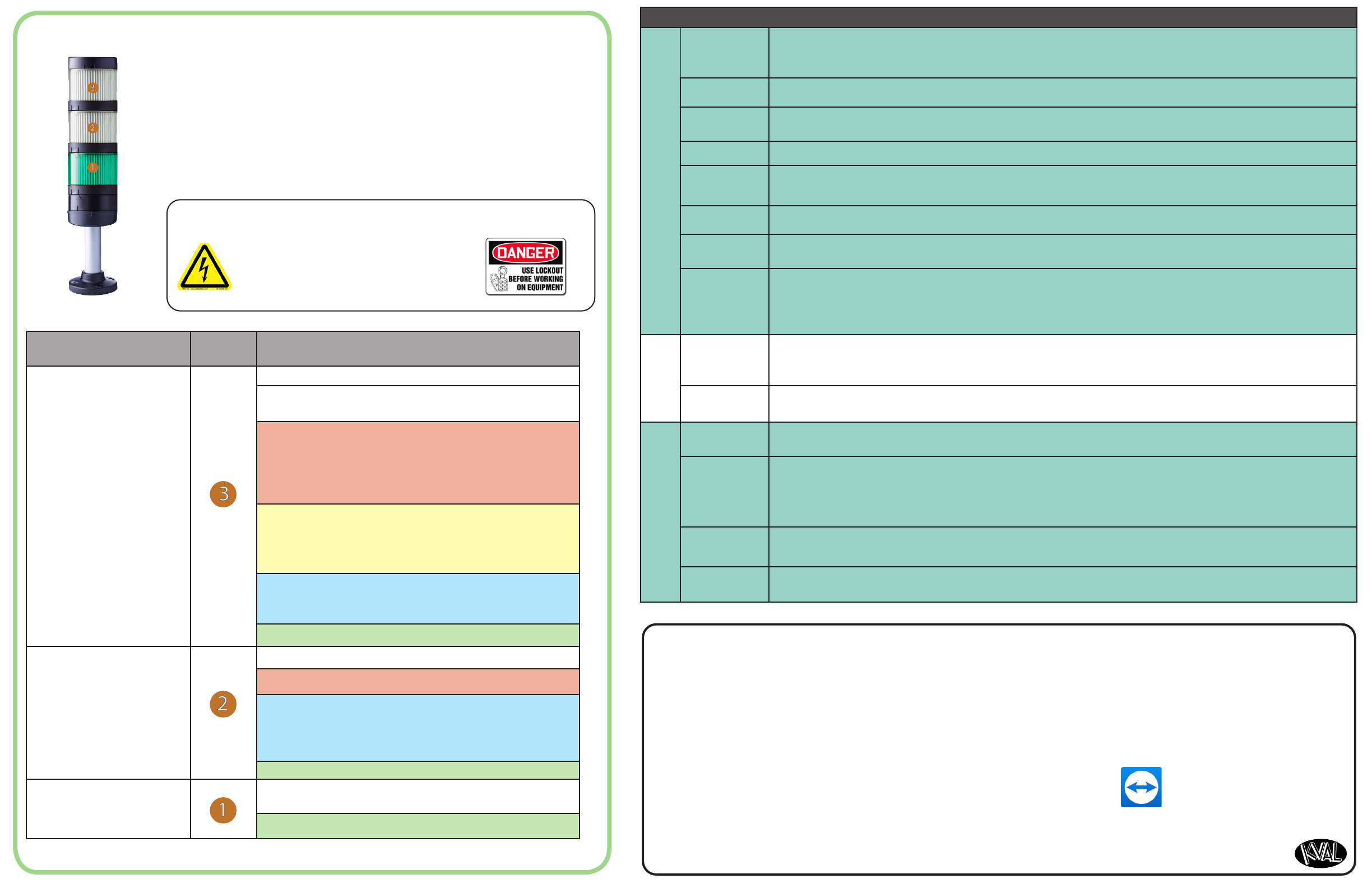
Categoy Desig. Descriptions
Machine Status
OFF (Clear): Machine not in operation.
White: Initializing
1 Flash: Waiting for all systems to initialize
Red: Machine Error
Solid: General Error
• 1 Flash: EtheCat Device not Ready to Run
• 2 Flashes: VFD, Sevo, or Motor Error
• 3 Flashes: 24 VDC Power Error
Yellow: External Error
Solid: General Error
• 1 Flash: 3 Phase Voltage Error
• 2 Flashes: Low Air Error
Blue: Operator Status
Solid: Waiting for Operator
• 1 Flash: Reposition Door
Green: Machine is Operational
Safey
OFF (Clear): Safey Project not Running
Red: Safey PLC Error
Blue: Waiting for Safey Re-Set
• Solid: General Error
• Flashing: Not Ready to Re-Stat (E-Sop Switch is Ac-
tive)
Green: Machine is Operational
Control Power
O: No Control Power
ON (Green): 24 VDC Control Power ON
About the Light Tower
Machine
High Voltage may cause injury or death.
Troubleshooting checks must be performed
by a Qualied Electrical Technician.
The Light Tower indicates the working status of the system. The
Light Tower is mounted on top of the Electrical Boxes. Each light dis-
plays dierent colors and lashing codes to show the machine status.
The table below describes the dierent states of the Lght Tower.
Be Smat! Follow all Safey Precautions.
Operation
Remote Troubleshooting
Kval’s Suppot Team is able to work remotely with your maintenance sta or contractor to diagnose and troubleshoot machin-
ey issues. To get stated, please create a suppot ticket online. Call (800)- 553-5825 or stat a suppot ticket Online htps://
www.kvalinc.com/suppot.
Tools Needed for machine hardware troubleshooting:
• Access to a broadband internet connection
• An iPhone or Android smat-phone (We use Apple FaceTime or
Google Duo for video)
• A DMM
• A standard toolset
For machine soware troubleshooting:
• Access to a broadband internet connection
• A computer running Windows
• Our remote suppot client
Allow Kval to Logon to the Machine
• Exit the KvalCAM program. On the
Windows Screen, select the KVAL
Sevice Icon

Other manuals for DL-NCD

2

Other Kval Industrial Equipment manuals

Kval MDA-66 Operation manual

Kval

Kval MDA-66 Operation manual

Kval 990FX User manual

Kval

Kval 990FX User manual

Kval 990-H User manual

Kval

Kval 990-H User manual

Kval 994-X User manual

Kval

Kval 994-X User manual

Kval Commander III User manual

Kval

Kval Commander III User manual

Kval 990FX User manual

Kval

Kval 990FX User manual

Kval Commander 3 User manual

Kval

Kval Commander 3 User manual

Kval 990-HQ User manual

Kval

Kval 990-HQ User manual

Kval EFX User manual

Kval

Kval EFX User manual

Kval 990-F4 User manual

Kval

Kval 990-F4 User manual

Kval 990-F4 User manual

Kval

Kval 990-F4 User manual

Kval 994-X Operation manual

Kval

Kval 994-X Operation manual

Kval Edge-SS User manual

Kval

Kval Edge-SS User manual

Kval 990-H User manual

Kval

Kval 990-H User manual

Kval EFX User manual

Kval

Kval EFX User manual

Kval 700-DC User manual

Kval

Kval 700-DC User manual

Kval MLX Operation manual

Kval

Kval MLX Operation manual

Kval 555 User manual

Kval

Kval 555 User manual

Kval 990-H User manual

Kval

Kval 990-H User manual

Kval 990FX Operation manual

Kval

Kval 990FX Operation manual

Kval MDA-6 Installation and operating instructions

Kval

Kval MDA-6 Installation and operating instructions

Kval 700-C User manual

Kval

Kval 700-C User manual

Kval 990-APEX User manual

Kval

Kval 990-APEX User manual

Kval Acro-HD Operation manual

Kval

Kval Acro-HD Operation manual

Popular Industrial Equipment manuals by other brands

Nederman ALU 150 user manual

Nederman

Nederman ALU 150 user manual

Schenker SMART 30 Installation, use and maintenance manual

Schenker

Schenker SMART 30 Installation, use and maintenance manual

Orwak 9020 Translation of original operating instructions

Orwak

Orwak 9020 Translation of original operating instructions

Endress+Hauser Micropilot FMR67 Safety instruction

Endress+Hauser

Endress+Hauser Micropilot FMR67 Safety instruction

WÜRGES HV Series operating instructions

WÜRGES

WÜRGES HV Series operating instructions

Allen-Bradley 140G EXT3 Series Installation

Allen-Bradley

Allen-Bradley 140G EXT3 Series Installation

T&D THERMON Terminator ZS-L-XP Installation procedures

T&D

T&D THERMON Terminator ZS-L-XP Installation procedures

ATD Tools Atd-7227 Operating instructions & parts manual

ATD Tools

ATD Tools Atd-7227 Operating instructions & parts manual

PCM VDF-201 operating instructions

PCM

PCM VDF-201 operating instructions

ABB A130-M65 Operation manual

ABB

ABB A130-M65 Operation manual

Siemens SIMATIC RTLS Series operating instructions

Siemens

Siemens SIMATIC RTLS Series operating instructions

Eaton NZM3-XKCO Series Instruction leaflet

Eaton

Eaton NZM3-XKCO Series Instruction leaflet

MAHLE Digital ADAS 2.0 instruction manual

MAHLE

MAHLE Digital ADAS 2.0 instruction manual

KREBER K-600 R user manual

KREBER

KREBER K-600 R user manual

erowa MTS 2.0 IntegralChuck M-P/A manual

erowa

erowa MTS 2.0 IntegralChuck M-P/A manual

Buhler GAS 222.21 Installation and operation instruction

Buhler

Buhler GAS 222.21 Installation and operation instruction

Thermo Scientific System I Installation, Operation, Basic Maintenance

Thermo Scientific

Thermo Scientific System I Installation, Operation, Basic Maintenance

Mayr ROBATIC 500.20_.0 Series Installation and operational instructions

Mayr

Mayr ROBATIC 500.20_.0 Series Installation and operational instructions

manuals.online logo
manuals.online logoBrands
  • About & Mission
  • Contact us
  • Privacy Policy
  • Terms and Conditions

Copyright 2025 Manuals.Online. All Rights Reserved.