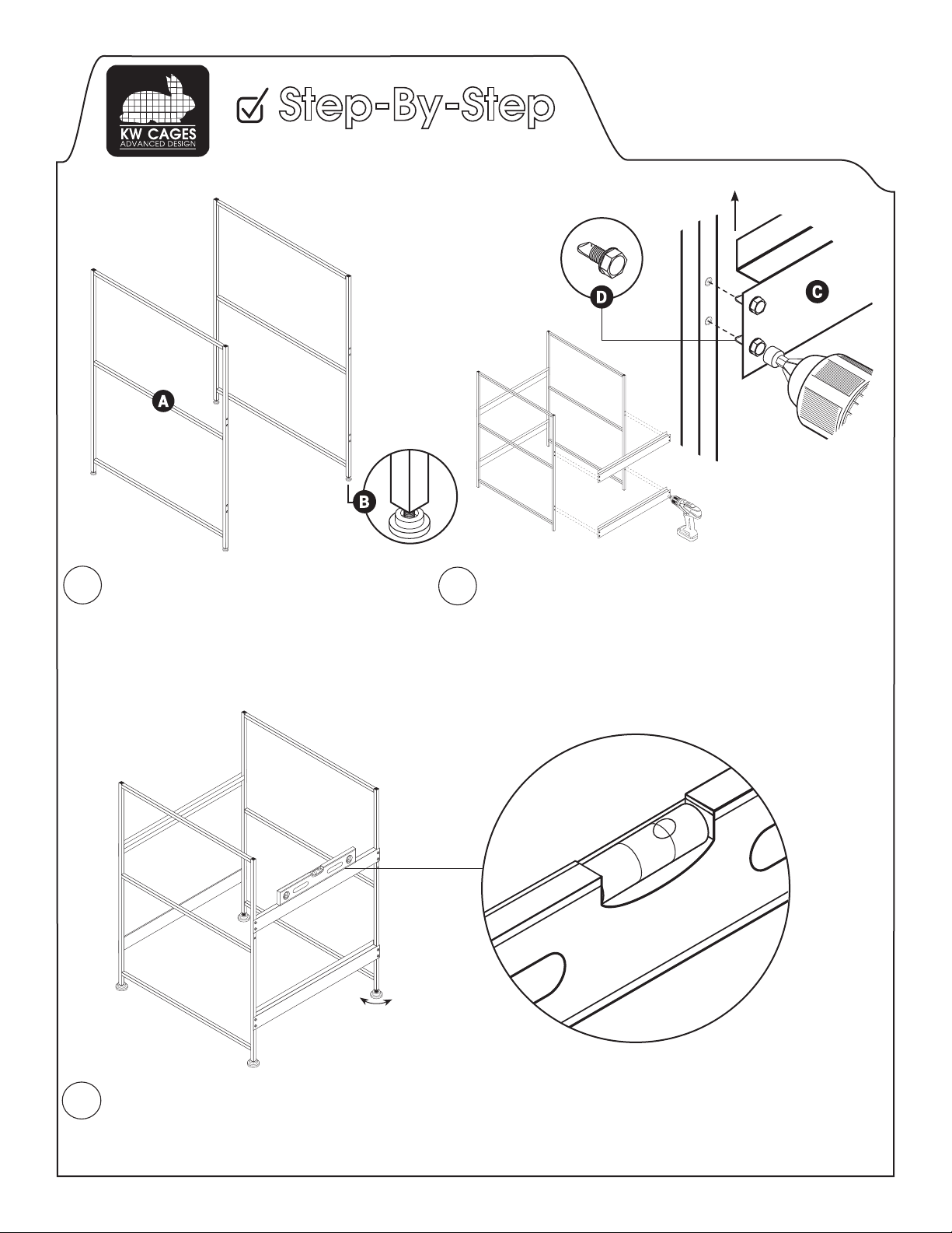
Attach self leveling feet (B) to the bottom
of each H-frame (A). Adjust leveling feet
to be approx. 1/8”-1/4” longer for each
successive section.
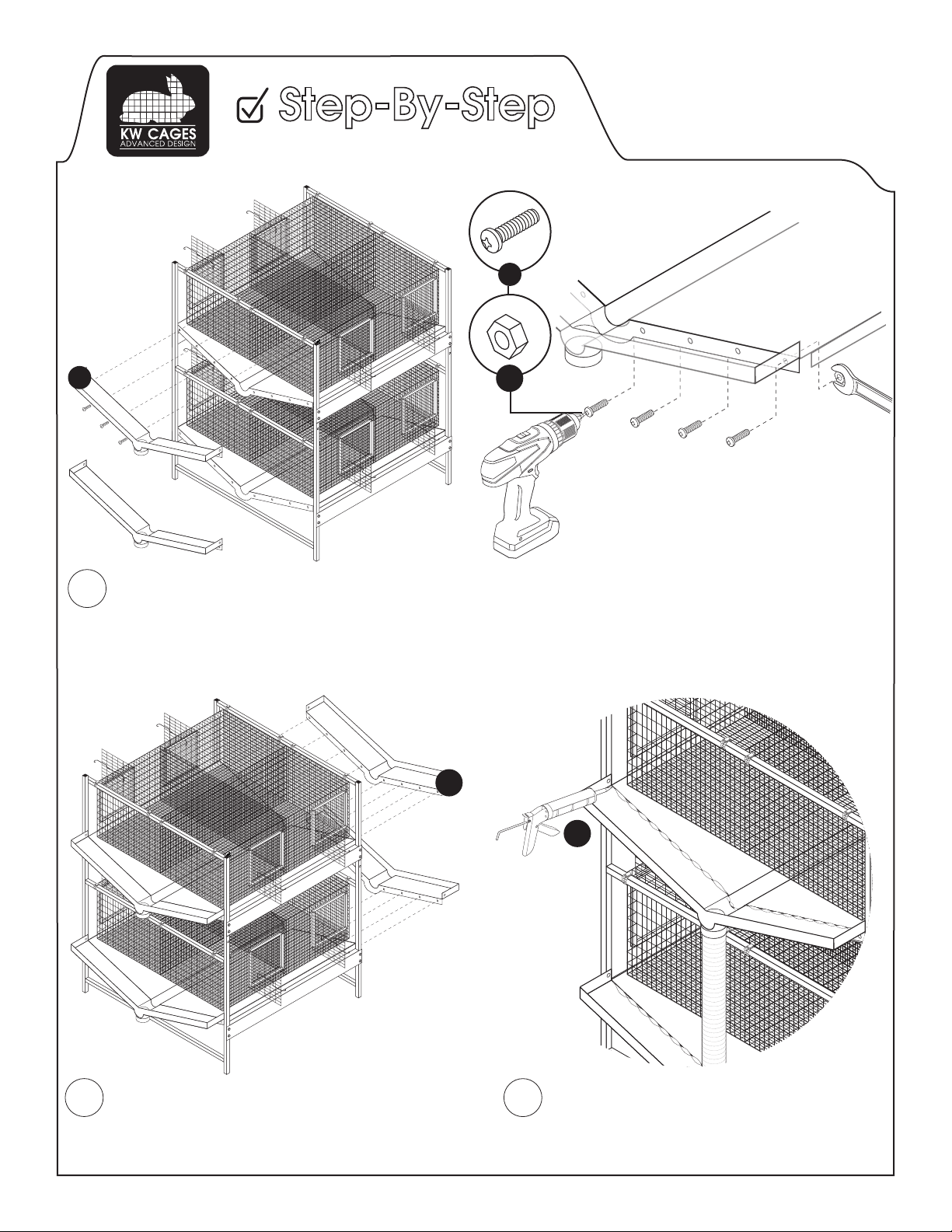
1Position support beam (C) to span across both H-Frame
sections. Attach support beam so that lip faces upward
to support plastic wash-down pan. Align holes in support
beam with dimples in H-Frame. Using drill with 3/8” hex
bit to drive stainless steel self drilling screws (D) into dim-
ple. Apply moderate pressure. Repeat on opposite side
until all four beams are attached.
2
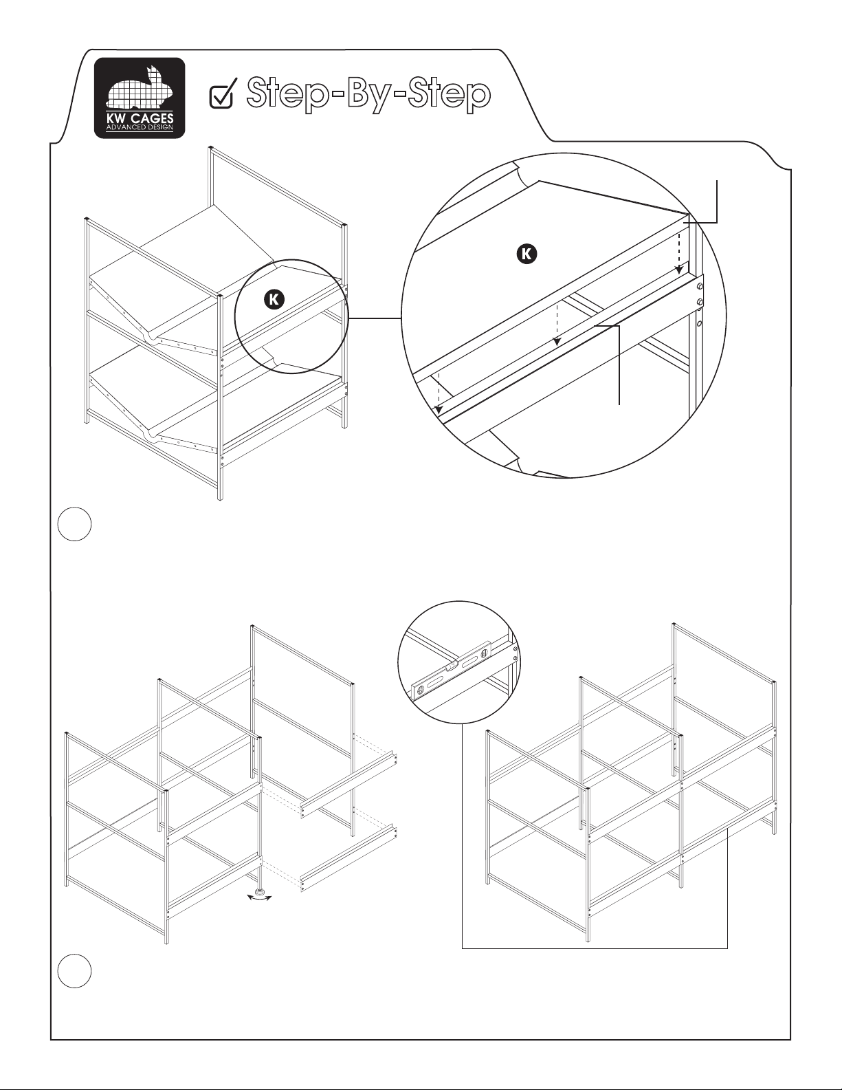
Adjust all leveling feet such that each frame is a minimum of 1/8” taller than the preceeding frame. See step
one for detail. A carpenters level can be used to check for consistent slop by maintaining the bubble slightly
off of center. This will ensure proper drainage toward the lower drain side when cleaning the Rabbitech System.
If add-on kits are installed, make sure to maintain the proper slope as units are added for optimal drainage. If
floor of building is not level more or less adjustment may be required.
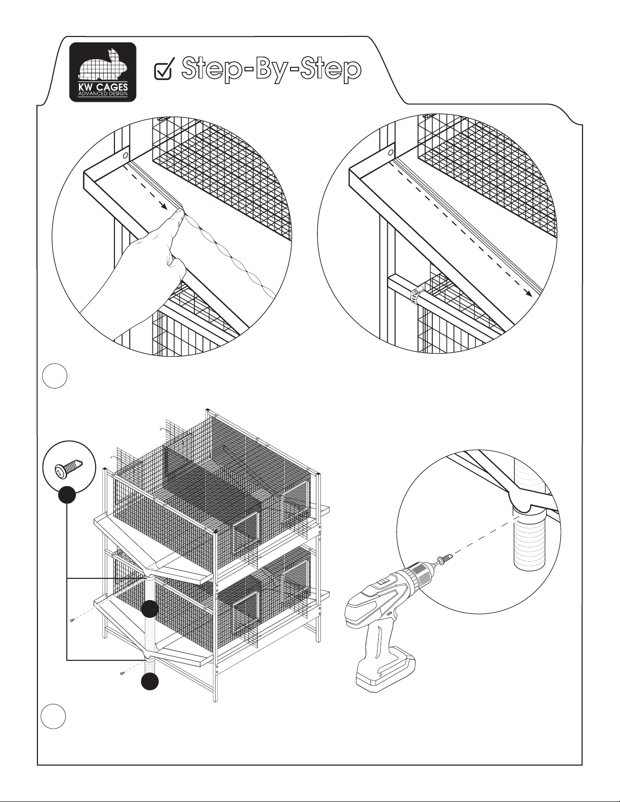
3
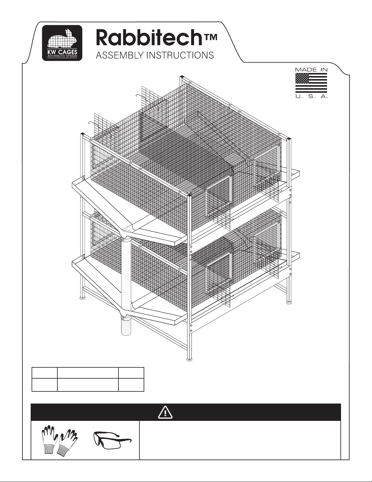
Frame Assembly
Support Beam Lip
Pro Tip: Use a carpenters level to check
that consistent slope is achieved.
Short Drain
Pipe
Long Drain
Pipe
Wash-Down Pan SS Hex
Tech Screw
SS Phillips
Tech Screw
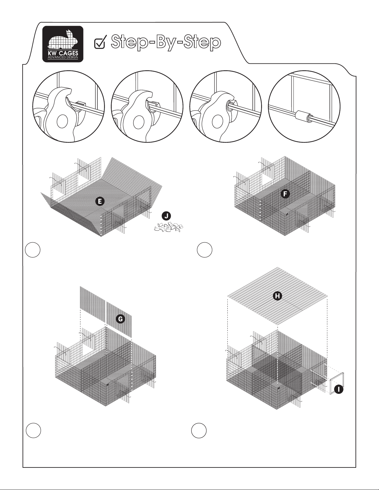
SS Bolt SS Nut Cage Clamp Clips Rings Silicone
+ -