Kymeta u8 User manual

Kymeta u8 Products Installation and
User Guide
Covers u8 terminal and u8 ODU configurations
Document number: 700-00121-000 revA
17 September 2020

Table of contents
1 Introduction 3
2 General considerations 4
2.1 Reduce the risk of RF exposure 4
2.2 Prevent RF interference 4
2.3 Prevent magnetic interference 5
2.4 Check electrical systems for safety 5
2.5 Site selection 5
2.6 QR code 7
3 Mount and power the u8 8
3.1 Connect the cables to the u8 ODU 9
4 Power on the u8 and access the antenna 10
4.1 Power on the u8 terminal and access the antenna 10
4.2 Power on the u8 ODU and access the antenna 11
4.3 Open the shroud access panel 11
4.4 Obtain u8 antenna status information 12
5 Provision and commission the u8 13
5.1 u8 terminal with Kymeta™ Broadband 13
5.2 u8 ODU or terminal without Kymeta™ Broadband 13
6 Set up the u8 terminal secondary SIM 14
7 u8 antenna orientation setup 15
8 u8 common troubleshooting steps 17
9 Customer support 18
10 Revision history 18
11 Copyright and trademark information 18
Appendix A. Kymeta u8 terminal cabling 19
Appendix B. Kymeta u8 ODU cabling 20
Appendix C. LED status indicators 21

3 17 September 2020
700-00121-000 revA Kymeta u8 products installation and user guide
© 2020 Kymeta Corporation. All rights reserved. Kymeta Corporation Confidential –
Subject to confidentiality obligations.
1 Introduction
This document contains important step-by-step details for the installation and setup of the Kymeta™ u8 terminal and
Kymeta™ u8 outdoor unit (ODU). Read this document in its entirety.
For information on the Kymeta u8 antenna web-based user interface and instructions on checking the antenna status,
refer to 700-00139-000 Kymeta™ u8 antenna software user guide.
For your safety, read 700-00122-000 Kymeta™ u8 products safety and handling guide before beginning installation.

4 17 September 2020
700-00121-000 revA Kymeta u8 products installation and user guide
© 2020 Kymeta Corporation. All rights reserved. Kymeta Corporation Confidential –
Subject to confidentiality obligations.
2 General considerations
Before beginning installation, read 700-00122-000 Kymeta™ u8 products safety and handling guide and ensure you
have all the installation hardware and tools required for u8 terminal assembly. Refer to the installation instructions
shipped with the u8 product kits. Installation tools are not provided with the product.
Place a piece of foam, fabric, or non-abrasive material on the clean flat surface to prevent marks or damage to the face of
the u8 antenna. Lift the u8 out of the case with two people (one person on each side), keeping the u8 parallel to the floor,
and lay it face down on the surface.
During installation, avoid obstructing the air intake screens or drain holes.
2.1 Reduce the risk of RF exposure
Install the u8 ODU or u8 terminal in an area above accessible range of personnel within the operational range of the
antenna to reduce the risk of RF exposure. Mount the terminal in an area that has limited access by people and does not
allow for people to pass through the path of the antenna beam in any direction the antenna beam may point.
2.2 Prevent RF interference
Do not install the u8 ODU or u8 terminal closer to radar equipment than the minimum safe distance specified in the
700-00122-000 Kymeta™ u8 products safety and handling guide. It may cause damage to the ODU.

5 17 September 2020
700-00121-000 revA Kymeta u8 products installation and user guide
© 2020 Kymeta Corporation. All rights reserved. Kymeta Corporation Confidential –
Subject to confidentiality obligations.
2.3 Prevent magnetic interference
Proximity to magnetic interference caused by motors, fans, or ferrous metals may increase acquisition times. Install the
u8 ODU or u8 terminal as far as possible from any equipment or materials that may cause magnetic interference for
faster acquisition times.
2.4 Check electrical systems for safety
Prior to installation, check that:
the ODU or terminal is grounded;
the electrical power is disconnected from the ODU or terminal;
in an ODU configuration, electrical connections are made to the ODU first and then to the modem; and
the power switch is in the off position before connecting electrical power to the modem.
Practice basic electrical safety measures. Follow local, national, and other regulations with respect to these devices.
2.5 Site selection
Obstructing the direct path to the satellite degrades performance and may cause a loss of connection with the
satellite. The antenna should have a clear line of sight: 15° – 90° elevation (broadside to 75° scan angle), full 360°
azimuth (broadside to 75° scan angle).
Obstructing the face of the antenna degrades RF performance and could impair the GPS capability of the antenna.
Satellite reacquisition is most efficient if you install the antenna in direction of travel; refer to 7 u8 antenna
orientation setup for more details.
✎If you need support in assessing your mounting configuration, contact Kymeta customer support at
support@kymetacorp.com for additional information.
The following images show example installation sites.

6 17 September 2020
700-00121-000 revA Kymeta u8 products installation and user guide
© 2020 Kymeta Corporation. All rights reserved. Kymeta Corporation Confidential –
Subject to confidentiality obligations.

7 17 September 2020
700-00121-000 revA Kymeta u8 products installation and user guide
© 2020 Kymeta Corporation. All rights reserved. Kymeta Corporation Confidential –
Subject to confidentiality obligations.
2.6 QR code
The u8 includes a QR code on the antenna communications module next to the LED status panel to show the as-built
configuration of the system.The following is an example of the information included in the QR code:
PRODUCT NAME:(E.G KYMETA U8 GEO TERMINAL, 20W)
PRODUCT_CODE: (E.G U8911-11113-P)
PRODUCT_SN: (E.G ABQ000K200624006)
ANTENNA SN: (E.G ABP511K200710025)
MODEM SN: (E.G 017806)
HD1 SN: (E.G 2937E989A746)
HD1 IMEI: (E.G 353533100504078)
IP ADDRESS: 192.168.44.2
SIM ID: (E.G. 890034011009200000000000000016259)

8 17 September 2020
700-00121-000 revA Kymeta u8 products installation and user guide
© 2020 Kymeta Corporation. All rights reserved. Kymeta Corporation Confidential –
Subject to confidentiality obligations.
3 Mount and power the u8
u8 terminals and u8 ODUs come with three non-terminated power cables exiting the shroud, as shown below:
Kymeta offers mounting solutions and power options for land-mobile and stationary installations of the u8 products
series. Depending on your installation specifics, follow the instructions provided with the mounting and power kits.
The u8 shroud includes the fan panel, the access panel, drain slots, and the egress for the cable bundles. Before
mounting the unit, you can open and remove the shroud without affecting the warranty or IP-rating. Open the shroud if
you need to access the connections or cables inside including the RX, TX, and Ethernet cable jumper or the power cable
connector to install an AC-to-DC power kit. See 3.1 Connect the cables to the u8 ODU for details. Refer to Appendix
B. Kymeta u8 ODU cabling for the cabling diagram.
When mounting the u8, keep at least a 12 in. (305 mm) open distance behind the fans and a minimum single exhaust
zone vertically (up or down), horizontally (right or left), or some combination to minimize backpressure.
The table below describes what u8 accessory kits are available to meet your installation needs.
Product configuration Land-mobile installation Stationary installation
u8 terminal
(U8911-11113-0 or
U8911-12113-0)
u8 ODU
(U8901-00112-0)
u8 terminal vehicle power kit
(U8ACC-00001-0)
see 700-00111-000 Kymeta u8 terminal
vehicle power kit installation instructions
shipped with the kit for installation
instructions
u8 terminal vehicle mounting kit
(U8ACC-00003-0)
see 700-00141-000 Kymeta u8 vehicle
mounting kit installation guide shipped
with the kit to for installation instructions
AC-to-DC power kit
(U8ACC-00002-0)
see 700-00142-000 AC-to-DC power kit
installation instructions shipped with the
kit for installation instructions
universal mounting plate
(U8ACC-000004-0)
see 700-00143-000 Universal mounting
plate installation instructions shipped with
the kit for installation instructions

9 17 September 2020
700-00121-000 revA Kymeta u8 products installation and user guide
© 2020 Kymeta Corporation. All rights reserved. Kymeta Corporation Confidential –
Subject to confidentiality obligations.
3.1 Connect the cables to the u8 ODU
The RX, TX, and Ethernet cables are shipped in a separate bag and you need to connect them before mounting the unit.
Refer to Appendix B. Kymeta u8 ODU cabling for the cabling diagram.
1. Place Kymeta u8 ODU shroud-up on a soft surface to protect the radome.
2. Loosen the five M6 captive fasteners on the fan panel. Gently
remove the panel and reach under the shroud to disconnect the
fan cable (W47B), then place the fan panel aside.
3. Remove the eight M6 fasteners on the shroud using the T20 Torx
driver. Gently lift the shroud off the terminal and set it aside. Note
that the cable glands on either side of the fan panel are not fixed
to the shroud and must be removed to modify power cable
routing.
4. Install the RX, TX, and Ethernet cables. Ensure they are routed through the correct cable gland.
✎If you use the AC-to-DC power kit, switch the power jumper cable now, while the shroud is open.
5. Set the shroud back in place and ensure the cable glands are properly secured. Re-install the eight M6 fasteners
from Step 3 and torque to 7.0 N-m (5.16 ft.-lb.). These fasteners have a nylon patch so Loctite is not required.
6. Set the fan panel in place and reconnect W47B under the shroud. Tighten the five M6 captive screws and torque
to 1.5 N-m (1.1 ft.-lb.). These fasteners have a nylon patch, so Loctite is not required.
7. Mount the Kymeta u8 ODU as required.

10 17 September 2020
700-00121-000 revA Kymeta u8 products installation and user guide
© 2020 Kymeta Corporation. All rights reserved. Kymeta Corporation Confidential –
Subject to confidentiality obligations.
4 Power on the u8 and access the antenna
4.1 Power on the u8 terminal and access the antenna
1. Ensure the terminal is in place with view of the sky, preferably, according to the guidelines in 2.5 Site selection.
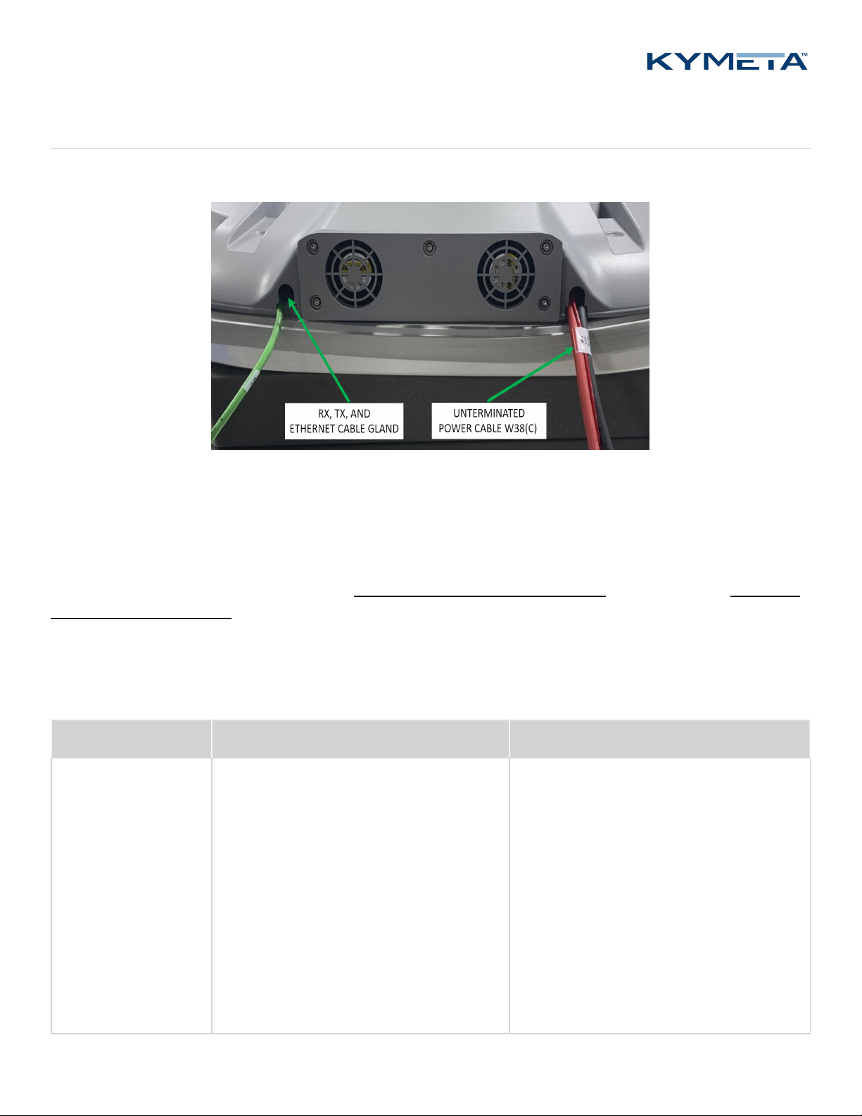
2. Check that all power cables are connected.
3. Power on the u8 terminal. You may hear the shroud fans power up, and then reduce speed.
4. Connect to the antenna's Wi-Fi. After 1-3 minutes, the Wi-Fi SSID of the terminal multi-WAN device becomes
active and available to interact with the terminal via the Kymeta Access application or Kymeta software
administrative web-based user interface (UI). Refer to the 700-00139-000 Kymeta™ u8 antenna software user
guide for details. Note: #### are four digits unique for each terminal.
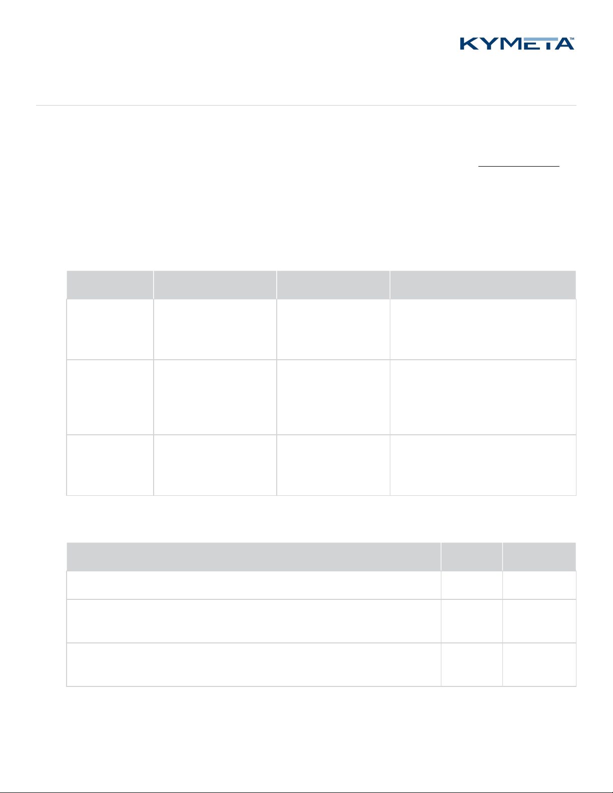
Antenna Wi-Fi SSID Default password Purpose
Administrative
access Wi-Fi
u8_Admin_#### Gen2 for the
World.
(Including the period)
Terminal administration including
accessing the Kymeta antenna web-
based UI and modem commissioning
Data access
Wi-Fi
u8_Internet_#### Kymeta brings
us together.
(Including the period)
Applications like general internet
browsing or streaming services that
do not permit operations through a
VPN
Data access Wi-
Fi with session
continuity
u8_SFC_#### Kymeta brings
us together.
(Including the period)
Applications that require continuity
like Wi-Fi calls or video conferences
5. (optional) Access the u8 system for administration or monitoring. Full system status is available through the
Kymeta Access application. This application also connects you to other system components for Administration.
Administration access Username Password
The antenna is available at the IPaddress 192.168.44.2 admin 2Cfg^Ant
Before commissioning, the satellite modem is available at the IP address:
192.168.44.1
admin P@55w0rd!
After commissioning with Kymeta Broadband, the satellite modem is available at
the IP address: 192.168.44.1.
admin iDirect
6. (optional) Change your Wi-Fi passwords using Kymeta Access application.

11 17 September 2020
700-00121-000 revA Kymeta u8 products installation and user guide
© 2020 Kymeta Corporation. All rights reserved. Kymeta Corporation Confidential –
Subject to confidentiality obligations.
Physical Ethernet access is also available. Access to the data network of the u8 is available by connecting to the
weatherized RJ45 connector on the Ethernet jumper cable from the shroud near the fan panel.
Physical access to the administrative network of the u8 is available by connecting to the Admin Ethernet port after
opening the access panel on the side. You need to set the static IP address of your administrative device to connect to
the antenna IP address 192.168.44.2 (e.g. 192.168.44.30). Operation in motion with the access panel open or with an
administrative Ethernet connection is not recommended. Refer to 4.3 Open the shroud access panel.
In the u8 terminal configuration, you have the option to install a second SIM for terrestrial communications. Refer to
6 Set up the u8 terminal secondary SIM for details.
4.2 Power on the u8 ODU and access the antenna
1. Ensure the ODU is in place with view of the sky according to guidelines in 2.5 Site selection.
2. Check that all cables are connected:
a. RX and TX cables are connected to the modem.
b. The Ethernet cable is connected to administrative port of modem or a network switch.
c. The power cable is connected to power source.
3. Power on the u8 ODU and external modem. You may hear the shroud fans power up, and then reduce speed.
4. After modem has booted, the antenna becomes accessible via wired Ethernet.
a. Set your local IPdevice to static IP address 192.168.0.11.
b. Accessthe Kymeta web-based UI at IP address 192.168.0.10.
Refer to 700-00139-000 Kymeta™ u8 antenna software user guide for more details.
Username: admin
Password: 2Cfg^Ant
A second physical Ethernet connection to the u8 ODU is available after opening the access panel on the side. Operation
in motion with the access panel open or with an administrative Ethernet connection is not recommended. See section
4.3 Open the shroud access panel for details on accessing the shroud access panel.
4.3 Open the shroud access panel
The shroud access panel provides access for:
Viewing LED status lights for the antenna, modem, and/or multi-WAN – refer to Appendix C. LED status indicators
for information about what each LED state indicates.
Accessing Ethernet port for physical administrative access
Utilizing the reset functionality of the antenna, modem, and/or multi-WAN
Adding a SIM

12 17 September 2020
700-00121-000 revA Kymeta u8 products installation and user guide
© 2020 Kymeta Corporation. All rights reserved. Kymeta Corporation Confidential –
Subject to confidentiality obligations.
To open the shroud access panel, do the
following:
1. Remove the two captive pan washer screws M6×16mm. Use a
T20 Torx drive.
2. Slide the panel toward you to remove. Note: The access panel
does not hinge. Downward pressure may damage the panel.
✎Operation in motion with the access panel removed or open is not recommended.
4.4 Obtain u8 antenna status information
After the terminal has booted, you can obtain status information in several ways.
1. In a terminal configuration, utilize the Kymeta Access application to view full terminal status.
2. In a terminal or ODU configuration, open the shroud access panel to view status LEDs. Solid green LEDs indicate
normal functioning, and blinking blue LEDs indicate connectivity. Refer to Appendix C. LED status indicators for
full LED status indicator definitions.
3. In a terminal or ODU configuration, open the shroud access panel and connect an Ethernet cable to the available
port. This Ethernet connection provides Kymeta Administrative web-based UI access according the directions in
the section above relevant to your configuration.
Refer to 700-00139-000 Kymeta™ u8 antenna software user guide for details on interacting with the features of the
Kymeta antenna. The software user guide provides you with details on all available features and modes of operation.

13 17 September 2020
700-00121-000 revA Kymeta u8 products installation and user guide
© 2020 Kymeta Corporation. All rights reserved. Kymeta Corporation Confidential –
Subject to confidentiality obligations.
5 Provision and commission the u8
5.1 u8 terminal with Kymeta™ Broadband
Contact support@kymetacorp.com to request a commissioning window. Provide your terminal serial number, contact
name and number, and requested commissioning window (7:00-18:00 PST).
Kymeta support will provision your terminal and provide you options files, which you will load with Kymeta support
during your commissioning window.
During your commissioning window, ensure your terminal has a clear view of the sky, and then contact Kymeta support
according to the instructions provided by the support team during the confirmation of your commissioning time. They
will guide you through the process of bringing your terminal online for the first time.
5.2 u8 ODU or terminal without Kymeta™ Broadband
For instructions refer to the 700-00139-000 Kymeta™ u8 antenna software user guide, section "Software
Commissioning Mode support".

14 17 September 2020
700-00121-000 revA Kymeta u8 products installation and user guide
© 2020 Kymeta Corporation. All rights reserved. Kymeta Corporation Confidential –
Subject to confidentiality obligations.
6 Set up the u8 terminal secondary SIM
In the u8 terminal configuration, you have the option to install a second SIM for terrestrial communications. To install a
second SIM card, do the following:
1. Remove the shroud access panel as described in 4.3 Open the
shroud access panel.
2. Use a screwdriver to remove the SIM cover.
3. Insert the second SIM in slot 2 by sliding the metal lock
mechanism to the “open” position. Flip out the empty SIM card
holder “2” and insert the second SIM.
4. Return the SIM holder to its original position ensuring that the
card is aligned properly and that the electronic pad of the card
mates with the contacts on the terminal. Then, slide the metal
locking mechanism back into position.
5. Attach the SIM cover with the four M4 x 6 mm screws.
6. Attach the access panel with the two captive pan washer screws M6×16mm. Use a T20 Torx drive.
7. Enable second SIM WAN through Kymeta Access or contact Kymeta customer support.
You will be able to adjust priority between all SIMs and satellite through the Kymeta Access application. Until this feature
is ready in Access in October 2020, contact Kymeta customer support for configuration experiments and adjustments.

15 17 September 2020
700-00121-000 revA Kymeta u8 products installation and user guide
© 2020 Kymeta Corporation. All rights reserved. Kymeta Corporation Confidential –
Subject to confidentiality obligations.
7 u8 antenna orientation setup
When in motion, the antenna’s yaw (heading), relative to north, is provided by the GPS heading. The Kymeta u8 antenna
out-of-the-box configuration assumes that the X axis of the antenna is aligned with the heading vector of the vehicle. If
this is not the case, you can set the vehicle to ant-yaw value to inform the antenna of the offset. Set the offset correctly
to expedite acquisition of the satellite while in motion.
✎If the offset is not set or is set incorrectly, the antenna can acquire the satellite, but it may take longer and will
result in more out-of-network time.
In the figure below, the antenna is correctly aligned, using the antenna’s default value of zero.
✎Make sure the Kymeta logo is front-facing and the fans are facing towards the rear of the car.
For an unaligned antenna, set vehicle-to-ant-yaw to the angle between the X axis and the heading vector as in the figure
below. The range is from -360° to 360° with positive angles representing a clockwise rotation of the antenna from the
vehicle heading vector.

16 17 September 2020
700-00121-000 revA Kymeta u8 products installation and user guide
© 2020 Kymeta Corporation. All rights reserved. Kymeta Corporation Confidential –
Subject to confidentiality obligations.
✎Ensure vehicle-to-antenna-roll and vehicle-to-antenna-pitch are set to their default values of 0. The onboard
accelerometers measure these values directly, so no offset is required.
You can adjust the vehicle-to-antenna-yaw offset value using the antenna’s API. Navigate to Help >API
Documentation >/setup/vehicle-to-ant. Then, set the necessary value. Refer to 700-00159-000 Kymeta™ u8
antenna public RESTful application programmers' interface reference for further information on using the RESTful
API.
✎The vehicle-to-antenna-yaw value will persist through software updates once set, but it will be removed with a
factory reset of the antenna.
✎For an adjustment to the vehicle-to-antenna-yaw to expedite acquisition under motion, the offset must be
accurately estimated to within 3°.

17 17 September 2020
700-00121-000 revA Kymeta u8 products installation and user guide
© 2020 Kymeta Corporation. All rights reserved. Kymeta Corporation Confidential –
Subject to confidentiality obligations.
8 u8 common troubleshooting steps
This section describes common issues and basic troubleshooting steps. If these steps fail to resolve your issue, please
contact Support.
1. The Wi-Fi never appears available to my device.
a. Check that the unit has power.
b. Open the access panel and check LED status indicators. If any indicators are yellow or red and/or flashing
rapidly, contact Kymeta customer support. Refer to Appendix C. LED status indicators for LED status
indicator definitions to assess if an error condition has been encountered. If any LEDs indicate an error
condition, contact Kymeta customer support.
2. My device is not able to access the IP addresses of the antenna or modem when connected via Wi-Fi.
a. Check the IP settings on your machine. The Wi-Fi should provide you an IP address either in the
10.10.10.XX range (Admin Wi-Fi) or in the 192.168.55.XX range (Internet Wi-Fi). If you did not receive any
of these IP addresses, turn off and on your Wi-Fi or try connecting to the other Wi-Fi network.
3. My device is not able to access the IP addresses of the antenna or modem when connected via physical Ethernet.
a. Check that you are connected to the expected Ethernet port (Admin or Data in the terminal configuration).
b. Check that your machine has a static IP address that can address the antenna at its IP address indicated in
4.1 Power on the u8 terminal and access the antenna.
4. I changed network configuration of one of the devices in my terminal and now cannot see it.
a. Use the Reset button under the access panel to reset the unit to default factory configuration.
5. The terminal is powered on, but the modem is not responding.
a. This is a known issue. Please review the software release notes and wait at least 6 minutes before rebooting
the terminal.

18 17 September 2020
700-00121-000 revA Kymeta u8 products installation and user guide
© 2020 Kymeta Corporation. All rights reserved. Kymeta Corporation Confidential –
Subject to confidentiality obligations.
9 Customer support
Contact Kymeta customer support at support@kymetacorp.com or 1-855-525-6638 (Monday to Friday, 07:00-
18:00 PT (UTC-8)).
10 Revision history
Revision Change
A Initial Production version.
11 Copyright and trademark information
©2020 Kymeta Corporation. All Rights Reserved. KYMETA, KYMETA CONNECT, KĀLO, CONNECTED BY KYMETA, and
MTENNA are trademarks of Kymeta Corporation, with registrations or pending applications in the U.S. and/or other
countries. All other trademarks are the property of their respective owners.

19 17 September 2020
700-00121-000 revA Kymeta u8 products installation and user guide
© 2020 Kymeta Corporation. All rights reserved. Kymeta Corporation Confidential –
Subject to confidentiality obligations.
Appendix A. Kymeta u8 terminal cabling
The power and Ethernet jumper cables move connection interfaces outside the u8 terminal shroud.

20 17 September 2020
700-00121-000 revA Kymeta u8 products installation and user guide
© 2020 Kymeta Corporation. All rights reserved. Kymeta Corporation Confidential –
Subject to confidentiality obligations.
Appendix B. Kymeta u8 ODU cabling
The power, Ethernet, RX, and TX jumper cables move connection interfaces outside the shroud.
Other manuals for u8
2
This manual suits for next models
3
Table of contents
Other Kymeta Touch Terminal manuals