Kymeta u8 User manual

Kymeta™ u8 Products
Installation and User Guide
Covers u8 terminal and u8 ODU configurations
Document number: 700-00121-000 revD
08 December 2020

Table of contents
1 Introduction and general considerations 4
1.1 Reduce the risk of RF exposure 5
1.2 Prevent RF interference 5
1.3 Prevent magnetic interference 5
1.4 Check electrical systems for safety 5
1.5 Site selection 5
1.6 Mounting considerations 7
1.7 Land-mobile installation considerations 7
1.8 Supported browser 7
1.9 QR code 8
2 u7-to-u8 upgrade kit installation considerations 9
2.1 Physical and mounting considerations 9
2.2 Cabling considerations 10
2.3 Power considerations 10
2.4 u7 product disposal 10
2.5 u7 product warranty 10
3 Unbox the u8 terminal 11
4 Open the u8 shroud 12
5 Install the u8 terminal 13
5.1 Get the u8 terminal ready 13
5.1.1 Mobile platform instructions 13
5.1.2 AC power source instructions 13
5.2 Mount the u8 terminal 13
5.2.1 Mobile platform instructions 13
5.2.2 Stationary platform instructions 13
5.3 Power on the u8 terminal and access the antenna 14
5.4 Provision and commission the u8 terminal with Kymeta™ Broadband services 15
5.4.1 Provision and commission the u8 terminal without Kymeta™ Broadband services 15
5.5 Set up the u8 terminal secondary SIM 16
6 Install the u8 ODU 17
6.1 Connect the cables to the u8 ODU 17
6.2 Mount the u8 ODU 18
6.3 Power on the u8 ODU and access the antenna 18

6.4 Provision and commission the u8 ODU 18
7 Obtain u8 antenna status information 19
7.1 Open the shroud access panel 19
8 Set up u8 antenna orientation 20
9 Network interfaces 22
10 Manage u8 antenna automatic reboot 25
11 Manage over-the-air (OTA) updates 25
11.1 OTAupdate process 25
11.2 Software rollback 25
12 Troubleshoot the u8 26
13 Replace components 26
14 Clean the u8 27
14.1 General cleaning 27
14.2 General cleaning agents 27
14.3 Hydrophobic coating reapplication 27
15 Package the Kymeta u8 terminal 28
16 Customer support 29
17 Revision history 29
18 Copyright and trademark information 29
Appendix A. Kymeta u8 terminal cabling diagram 30
Appendix B. Kymeta u8 ODU cabling diagram 32
Appendix C. LED status indicators 34
Appendix D: u8 accessories available for purchase 36
Appendix E: u8 ODU and u8 terminal parts available for purchase 37
Appendix F: Device login information 38

© 2020 Kymeta Corporation. All rights reserved. 4 08 December 2020
700-00121-000 revD Kymeta u8 products installation and user guide
1 Introduction and general considerations
This document contains important step-by-step details for the installation and setup of the Kymeta™ u8 terminal and
Kymeta™ u8 outdoor unit (ODU). Read this document in its entirety.
For information on the Kymeta u8 antenna web-based user interface, refer to 700-00139-000 Kymeta™ u8 antenna
software user guide.
For your safety, read 700-00122-000 Kymeta™ u8 products safety and handling guide before beginning installation.
✎This document also contains important u7-to-u8 terminal upgrade considerations.
Refer to 2 u7-to-u8 upgrade kit installation considerations for details.
Ensure you have all the installation hardware and tools required for u8 terminal assembly. Installation tools are not
provided with the product. If you ordered any u8 accessory kit(s) to accompany your u8 terminal or u8 ODU, refer to the
installation instructions shipped with the kit(s).
During installation, avoid obstructing the air intake screens or drain holes.
✎Never grab or lift the u8 by the shroud, diplexer or any other part of the RF chain. Never use the diplexer or any
part of the RF chain to mount the ODU as they are not a structural part of the u8 and may be damaged if handled
improperly. Avoid damaging the coating on the diplexer.
Use the corner handles to lift the u8.
Figure 1. u8 terminal and u8 ODU external guide

© 2020 Kymeta Corporation. All rights reserved. 5 08 December 2020
700-00121-000 revD Kymeta u8 products installation and user guide
1.1 Reduce the risk of RF exposure
Install the u8 ODU or u8 terminal in an area above accessible range of personnel within the operational range of the
antenna to reduce the risk of RF exposure. Mount the terminal in an area that has limited access by people and does not
allow for people to pass through the path of the antenna beam in any direction the antenna beam may point.
u8 terminals operating under Kymeta FCC blanket authorization (call sign: E170070) must limit BUC output power to
42.3 dBm to maintain compliance with RF safety labeling on the unit ensuring general public safety during transmit
operations. Limiting BUC output power and mounting above the human users or appropriately marking a keep-out area
ensure safe exposure limits for all users.
1.2 Prevent RF interference
Do not install the u8 ODU or u8 terminal closer to radar equipment than the minimum safe distance specified in the
700-00122-000 Kymeta™ u8 products safety and handling guide. It may cause damage to the ODU.
1.3 Prevent magnetic interference
Proximity to magnetic interference caused by motors, fans, or ferrous metals may increase acquisition times. Install the
u8 ODU or u8 terminal as far as possible from any equipment or materials that may cause magnetic interference for
faster acquisition times.
1.4 Check electrical systems for safety
Prior to installation, check that:
the ODU or terminal is grounded;
the electrical power is disconnected from the ODU or terminal; and
in an ODU configuration, electrical connections are made to the ODU first and then to the modem.
Practice basic electrical safety measures. Follow local, national, and other regulations with respect to these devices.
1.5 Site selection
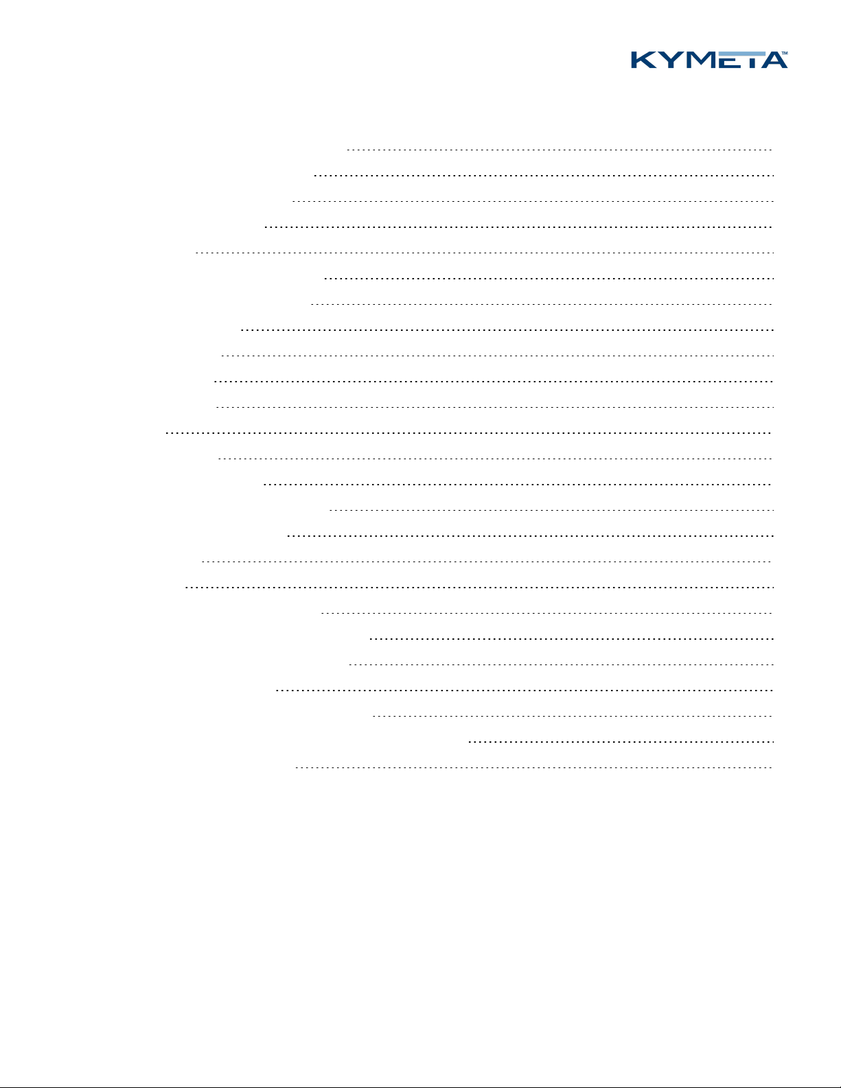
Obstructing the direct path to the satellite degrades performance and may cause a loss of connection with the
satellite. The antenna should have a clear line of sight: 15° – 90° elevation (broadside to 75° scan angle), full 360°
azimuth (broadside to 75° scan angle).
Obstructing the face of the antenna degrades RF performance and could impair the GNSS capability of the antenna.
Satellite reacquisition is most efficient if you install the antenna in direction of travel; refer to 8 Set up u8 antenna
orientation for more details.

© 2020 Kymeta Corporation. All rights reserved. 6 08 December 2020
700-00121-000 revD Kymeta u8 products installation and user guide
✎If you need support in assessing your mounting configuration, contact Kymeta customer support at
support@kymetacorp.com for additional information.
The following images show example installation sites.
Figure 2. Land-mobile installation
Figure 3. Stationary installation

© 2020 Kymeta Corporation. All rights reserved. 7 08 December 2020
700-00121-000 revD Kymeta u8 products installation and user guide
Figure 4. Maritime installation
1.6 Mounting considerations
Any mounting solution designed for the u8 antenna, u8 ODU, or u8 terminal must allow for lateral and vertical thermal
expansion and contraction of the unit. Rigid constraint of the unit may result in permanent damage to the unit, including
catastrophic failure, and voids the warranty of the u8 product. Kymeta recommends a minimum clearance of 1.5 cm (0.6
in.) of clearance from the antenna/ODU terminal edge to account for this thermal expansion.
✎When mounting the u8, keep at least a 12 in. (305 mm) open distance behind the fans and a minimum single
exhaust zone vertically (up or down), horizontally (right or left), or some combination to minimize backpressure.
1.7 Land-mobile installation considerations
For safety to your vehicle and rack system, obey all posted speed limits and traffic cautions. Adapt your speed to the
conditions of the road and the load being carried.
1.8 Supported browser
Use Mozilla Firefox to access the Kymeta web-based user interface (UI).

© 2020 Kymeta Corporation. All rights reserved. 8 08 December 2020
700-00121-000 revD Kymeta u8 products installation and user guide
1.9 QR code
The u8 includes a QR code on the antenna communications module next to the LED status panel to show the as-built
configuration of the system.The following is an example of the information included in the QR code:
PRODUCT NAME:(E.G KYMETA U8 GEO TERMINAL, 20W)
PRODUCT_CODE: (E.G U8911-11113-P)
PRODUCT_SN: (E.G ABQ000K200624006)
ANTENNA SN: (E.G ABP511K200710025)
MODEM SN: (E.G 017806)
HD1 SN: (E.G 2937E989A746)
HD1 IMEI: (E.G 353533100504078)
IP ADDRESS: 192.168.44.2
SIM ID: (E.G. 890034011009200000000000000016259)

© 2020 Kymeta Corporation. All rights reserved. 9 08 December 2020
700-00121-000 revD Kymeta u8 products installation and user guide
2 u7-to-u8 upgrade kit installation considerations
This section describes u7-to-u8 terminal upgrade considerations. For the major design features of the u8 terminal refer
to 1 Introduction and general considerations.
2.1 Physical and mounting considerations
The footprint of the u8 terminal is 89.5 cm × 89.5 cm × 14 cm (35.2 in. × 35.2 in. × 5.5 in.), which is slightly larger
than the u7 footprint. Before you begin installation of the u8, ensure you have enough mounting space for the
increased footprint size.
Figure 5. u8 terminal dimensions
The u8 has a different mounting hole pattern than the u7. To mount the u8, you need to purchase the universal
mounting plate (U8ACC-00004-0) or build your own mounting solution. For more information on the universal
mounting plate and mounting the u8, see 5.2 Mount the u8 terminal and 700-00143-000 Universal mounting
plate installation instructions.
The physical design of the u8 requires enough space around the u8 to avoid blockage of some elements. This
includes the following:
The u8 has all cables routed out the side next to the fans. Ensure when mounting and installing the u8 that this
space isn't blocked.
The u8 terminal fans are critical to proper thermal function; refer to 1 Introduction and general
considerations for terminology. When mounting the u8, keep at least a 305 mm (12 in.) open distance behind
the fans and a minimum single exhaust zone vertically (up or down), horizontally (right or left), or some
combination to minimize backpressure.
The u8 terminal access panel on one side is removable for LED/admin Ethernet access. You need to ensure that
this panel is reachable after you have mounted and installed the u8.

© 2020 Kymeta Corporation. All rights reserved. 10 08 December 2020
700-00121-000 revD Kymeta u8 products installation and user guide
2.2 Cabling considerations
The u8 terminal comes with the Ethernet jumper cable that extends the Ethernet connection outside of the shroud.
For more information on u8 cabling and the u8 products cable extension kit, see Appendix A. Kymeta u8 terminal
cabling diagram
The u7-to-u8 terminal upgrade kit ships with the u8 customer Ethernet cable (25' length). If you want to use this
LAN connection, you need to remove the shroud and install the Ethernet jumper cable.
The u7-to-u8 terminalupgrade kit ships with a power jumper cable. If you want an AC solution, you need to
purchase the AC-to-DC power kit (U8ACC-00002-0).
If you are replacing a u7 terminal mounted on a vehicle, consider purchasing a u8 vehicle power kit (U8ACC-
00001-0).
2.3 Power considerations
The u7 is configured by default to be used with an AC power via the I/O box or onboard power supply and requires
a 40 VDC power source.
The u8 is configured by default to use a DC power source and requires a 12 VDC to 36 VDC power source. To use
an AC power source for the u8, purchase the AC-to-DC power kit (U8ACC-00002-0).
For more information on the power specifics of the u8, refer to 5.1.2 AC power source instructions
2.4 u7 product disposal
If you want to dispose of your u7 product, follow your local disposal regulations.
2.5 u7 product warranty
Warranty for the u7 is terminated 30 days after the u8 ships.

© 2020 Kymeta Corporation. All rights reserved. 11 08 December 2020
700-00121-000 revD Kymeta u8 products installation and user guide
3 Unbox the u8 terminal
1. Clear a flat surface: place a piece of foam, fabric, or non-abrasive material on the clean flat surface to prevent
marks or damage to the face of the u8 antenna.
2. Unpack the terminal. To open the box, lay it flat on an open area where it's easy for one person to stand on each
side near the clean assembly surface.
3. With two people (one person on each side), lift the u8 out of the case, keeping the antenna parallel to the floor,
and lay the antenna face down on the clean flat surface. Place a piece of foam, fabric, or non-abrasive material on
the clean flat surface to prevent marks or damage to the face of the antenna.
✎The u8 terminal box includes a large grey foam piece to protect the top of the u8 during transportation. Use this
as a protective pad when working on the u8.

© 2020 Kymeta Corporation. All rights reserved. 12 08 December 2020
700-00121-000 revD Kymeta u8 products installation and user guide
4 Open the u8 shroud
✎This step is optional.
The u8 shroud includes the fan panel, the access panel, drain slots, and the egress for the cable bundles. Before installing
and mounting the unit, you can open and remove the shroud without affecting the warranty or IP-rating. Open the
shroud if you need to access the connections or cables inside including the RX, TX, and Ethernet cable jumper or the
power cable connector to install an AC-to-DC power kit.
To open the shroud, follow the instructions below:
1. Place Kymeta u8 terminal shroud-up on a soft surface to protect the radome.
2. Remove the eight M6 fasteners on the shroud using the T20 Torx driver.
✎The cable glands on either side of the fan panel are not fixed to the shroud and must be removed to
modify power cable routing.
3. Gently lift the shroud until the fan cable connector is accessible. Disconnect the section attached to the fans and
fan panel by unlocking the outdoor-rated Ethernet connector, and gently pulling to release. Then, fully remove
the shroud and place it aside.
✎Removing the fan panel from the shroud is not necessary.
4. Access the connections or cables inside including the RX, TX, and Ethernet cable jumper or the power cable
connector to install an AC-to-DC power kit. If you have a u8 ODU, refer to 6.1 Connect the cables to the u8
ODU to connect all cables before replacing the shroud.
5. Reconnect the fan cable, and then set the shroud back in place and ensure the cable glands are properly secured.
Pay special attention to the seating of the shroud, and the location of the cables beneath it. Ensure that the RF,
power, and fan connector cables are clear of the 4 mounting points. Re-install the eight M6 fasteners from Step 2
and torque to 7.0 N-m (5.16 ft.-lb.). These fasteners have a nylon patch so Loctite is not required.
For more information, refer to 6.1 Connect the cables to the u8 ODU,Appendix A. Kymeta u8 terminal cabling
diagram, and Appendix B. Kymeta u8 ODU cabling diagram.
For information on the available u8 accessory kits to support your installation needs refer to section Appendix D: u8
accessories available for purchase.

© 2020 Kymeta Corporation. All rights reserved. 13 08 December 2020
700-00121-000 revD Kymeta u8 products installation and user guide
5 Install the u8 terminal
5.1 Get the u8 terminal ready
5.1.1 Mobile platform instructions
Installing the u8 terminal on a car is similar to installing an audio amplification system. Kymeta recommends contacting
an authorized auto shop to install the u8 terminal on your car.
The u8 terminal accepts 12 V to 36 V DC maximum power and integrates with most platforms.
Kymeta offers u8 vehicle power kit (U8ACC-00001-0) for land-mobile installation of the u8 terminal. Depending on your
installation specifics, follow the 700-00111-000 Kymeta u8 terminal vehicle power kit installation instructions
provided with the power kit.
5.1.2 AC power source instructions
The u8 terminal accepts DC voltage, so you need an AC-to-DC power supply to power the antenna with a standard wall
outlet. Kymeta sells an IP-67-rated AC-to-DC power kit (U8ACC-00002-0) as an accessory to the u8.
1. Open the shroud as described in section 4 Open the u8 shroud.
2. For physical Ethernet access to the data network of the u8, connect to the weatherized Ethernet jumper cable
(W57) to the data port on the communication module. The Ethernet cable is shipped unattached in a separate
bag.
3. Install the AC-to-DC power kit (U8ACC-00002-0). Follow the 700-00142-000 AC-to-DC power kit installation
instructions shipped with the kit.
4. Set the shroud back as described in Step 5 in section 4 Open the u8 shroud.
5.2 Mount the u8 terminal
5.2.1 Mobile platform instructions
Kymeta offers u8 vehicle mounting kit (U8ACC-00003-0) for land-mobile installation of the u8 terminal. Follow the
instructions from the 700-00141-000 Kymeta u8 vehicle mounting kit installation guide provided with the
mounting kit.
5.2.2 Stationary platform instructions
Kymeta offers universal mounting plate (U8ACC-00004-0) for stationary installation of the u8 terminal. Follow the
instructions from the 700-00143-000 Universal mounting plate installation instructions provided with the mounting
kit.

© 2020 Kymeta Corporation. All rights reserved. 14 08 December 2020
700-00121-000 revD Kymeta u8 products installation and user guide
5.3 Power on the u8 terminal and access the antenna
1. Ensure the terminal is in place with view of the sky, preferably, according to the guidelines in 1.5 Site selection.
2. Check that all power cables are connected.
3. Power on the u8 terminal. You may hear the shroud fans power up, and then reduce speed.
⚠The Kymeta u8 antenna operates on 12 VDC to 36 VDC maximum. Exceeding 36 VDC may cause damage
to the equipment and is not covered under warranty.
4. Connect to the antenna's Wi-Fi. After 1-3 minutes, the Wi-Fi SSID of the terminal multi-WAN device becomes
active and available to interact with the terminal via the Kymeta Access application or Kymeta software
administrative web-based user interface (UI). Refer to the 700-00139-000 Kymeta™ u8 antenna software user
guide for details. Note: #### are four digits unique for each terminal.
Antenna Wi-Fi SSID Default password Purpose
Administrative
access Wi-Fi
u8_Admin_#### Gen2 for the
World.
(Including the period)
Terminal administration including
accessing the Kymeta antenna web-
based UI and modem commissioning
Data access
Wi-Fi
u8_Internet_#### Kymeta brings
us together.
(Including the period)
Applications like internet browsing or
streaming services that don't permit
operations through a VPN
Data access Wi-
Fi with session
continuity
u8_SFC_#### Kymeta brings
us together.
(Including the period)
Applications that require continuity
like Wi-Fi calls or video conferences
5. (optional) Access the u8 system for administration or monitoring. Full system status is available through the
Kymeta Access application. This application also connects you to other system components for Administration.
Refer to Appendix F: Device login information for details.
6. Change your Wi-Fi passwords using Kymeta Access application.
Physical access to the administrative network of the u8 is available by connecting to the Admin Ethernet port after
opening the access panel on the side. You need to set the static IP address of your administrative device to connect to
the antenna IP address 192.168.44.2 (e.g. 192.168.44.30). Operation in motion with the access panel open or with an
administrative Ethernet connection is not recommended. Refer to 7.1 Open the shroud access panel.
In the u8 terminal configuration, you have the option to install a second SIM for terrestrial communications. Refer to 5.5
Set up the u8 terminal secondary SIM for details.

© 2020 Kymeta Corporation. All rights reserved. 15 08 December 2020
700-00121-000 revD Kymeta u8 products installation and user guide
5.4 Provision and commission the u8 terminal with Kymeta™
Broadband services
Contact support@kymetacorp.com to request a commissioning window. Provide your terminal serial number, contact
name and number, and requested commissioning window 07:00-18:00 PT (UTC-8).
Kymeta support will provision your terminal and provide you options files before the call, which you will load with
Kymeta support during your commissioning window.
Before commissioning, ensure your administrative laptop has access to the u8 administrative network, either with the
physical access under the access panel, or wirelessly on the Admin Wi-Fi network. See Appendix F: Device login
information for login information.
During your commissioning window, ensure your terminal has a clear view of the sky, and then contact Kymeta support
according to the instructions provided by the support team during the confirmation of your commissioning time. They
will guide you through the process of bringing your terminal on satellite for the first time.
5.4.1 Provision and commission the u8 terminal without Kymeta™ Broadband services
For instructions refer to the 700-00139-000 Kymeta™ u8 antenna software user guide, section "Software
Commissioning Mode support".

© 2020 Kymeta Corporation. All rights reserved. 16 08 December 2020
700-00121-000 revD Kymeta u8 products installation and user guide
5.5 Set up the u8 terminal secondary SIM
In the u8 terminal configuration, you have the option to install a second SIM for terrestrial communications. To install a
second SIM card, do the following:
1. Remove the shroud access panel as described in 7.1 Open the
shroud access panel.
2. Use a screwdriver to remove the SIM cover.
3. Insert the second SIM in slot 2 by sliding the metal lock
mechanism to the “open” position. Flip out the empty SIM card
holder “2” and insert the second SIM.
4. Return the SIM holder to its original position ensuring that the
card is aligned properly and that the electronic pad of the card
mates with the contacts on the terminal. Then, slide the metal
locking mechanism back into position.
5. Attach the SIM cover with the four M4 x 6 mm screws.
6. Attach the access panel with the two captive pan washer screws M6×16mm. Use a T20 Torx drive.
7. Enable second SIM WAN through Kymeta Access application or portal or contact Kymeta customer support.
Adjust priority between all SIMs and satellite through the Kymeta Access application.

© 2020 Kymeta Corporation. All rights reserved. 17 08 December 2020
700-00121-000 revD Kymeta u8 products installation and user guide
6 Install the u8 ODU
6.1 Connect the cables to the u8 ODU
The RX, TX, and Ethernet cables are shipped in a separate bag and you need to connect them before mounting the unit.
Refer to Appendix B. Kymeta u8 ODU cabling diagram for the u8 ODU cabling diagram.
1. Place Kymeta u8 ODU shroud-up on a soft surface to protect the radome.
2. Open the shroud as described in 4 Open the u8 shroud.
3. Connect the RX jumper cable (W58) to the communication module. Ensure it is routed through the correct cable
gland. Ensure the RX connector is not cross threaded and that it is secure. The RX jumper cable (W58) is
identifiable by its short length and its right-angled connector. The right-angle connector should be connected to
the antenna communication module to enable proper routing of the cable through the shroud cable gland.
⚠When installing the RX and TX cables, ensure the center pin of the cabled connector is aligned to the center
pin receptacle on the communication module. Press the cabled connector onto the threaded communication
module receptacle and hand-tighten the outer ring clockwise until the threads are engaged and the outer ring
no longer spins. Ensure it is routed through the correct cable gland. Ensure the RX connector is not cross
threaded and that it is secure; the connector will not cover all available threads.
4. Connect the TX jumper cable (W59) to the BUC. The TX jumper cable is identifiable by its short length, and it is
labeled “TX”. Ensure it is routed through the correct cable gland.
5. For physical Ethernet access to the u8 ODU for OpenAMIP communication to the modem, connect the
weatherized Ethernet jumper cable (W57) to the data port on the communication module. Ensure it is routed
through the correct cable gland. The Ethernet jumper cable (W57) is identifiable by its short length, and it has one
male and one female outdoor-rated connector. Use the male connector end of the cable at the communication
module, leaving the female cable connector outside the shroud for connection, by a longer cable, to the modem.
✎If you use the AC-to-DC power kit (U8ACC-00002-0), switch the power jumper cable now, while the
shroud is open.
6. Set the shroud back as described in Step 5 in 4 Open the u8 shroud. Ensure the cable glands are properly
secured.
7. Mount the Kymeta u8 ODU as required.
✎Check that all screws are tight before lifting the ODU.
✎Kymeta recommends that installers, integrators, and handlers of the u8 do not lift or hold the u8 by using any of
the RF chain as a handle or grip, or by any mounted components or cables. Always lift the u8 by the corner handles.

© 2020 Kymeta Corporation. All rights reserved. 18 08 December 2020
700-00121-000 revD Kymeta u8 products installation and user guide
6.2 Mount the u8 ODU
Mounting the u8 ODUis the same as mounting the u8 terminal. Refer to 5.2 Mount the u8 terminal for details.
6.3 Power on the u8 ODU and access the antenna
1. Ensure the ODU is in place with view of the sky according to guidelines in 1.5 Site selection.
2. Check that all cables are connected:
a. RX and TX cables are connected to the modem.
b. The Ethernet cable is connected to administrative port of modem or a network switch.
c. The power cable is connected to power source.
3. Power on the u8 ODU and external modem. You may hear the shroud fans power up, and then reduce speed.
⚠The Kymeta u8 antenna operates on 12 VDC to 36 VDC maximum. Exceeding 36 VDC may cause damage
to the equipment and is not covered under warranty.
4. After modem has booted, the antenna becomes accessible via wired Ethernet.
a. Set your local IPdevice to static IP address 192.168.0.11.
b. Accessthe Kymeta web-based UI at IP address 192.168.0.10. See Appendix F: Device login information
for details, and refer to 700-00139-000 Kymeta™ u8 antenna software user guide for web-based UI
details.
A second physical Ethernet connection to the u8 ODU is available after opening the access panel on the side. Operation
in motion with the access panel open or with an administrative Ethernet connection is not recommended. See section
7.1 Open the shroud access panel for details on accessing the shroud access panel.
6.4 Provision and commission the u8 ODU
For instructions refer to the 700-00139-000 Kymeta™ u8 antenna software user guide, section "Software
Commissioning Mode support".

© 2020 Kymeta Corporation. All rights reserved. 19 08 December 2020
700-00121-000 revD Kymeta u8 products installation and user guide
7 Obtain u8 antenna status information
After the terminal has booted, you can obtain status information in several ways.
1. In a terminal configuration, utilize the Kymeta Access application to view full terminal status.
2. In a terminal or ODU configuration, open the shroud access panel as described in 7.1 Open the shroud access
panel to view status LEDs. Solid green LEDs indicate normal functioning, and blinking blue LEDs indicate
connectivity. Refer to Appendix C. LED status indicators for full LED status indicator definitions.
3. In a terminal or ODU configuration, open the shroud access panel as described in 7.1 Open the shroud access
panel and connect an Ethernet cable to the available port. This Ethernet connection provides Kymeta
Administrative web-based UI access according the directions in the section above relevant to your configuration.
Refer to 700-00139-000 Kymeta™ u8 antenna software user guide for details on interacting with the features of the
Kymeta antenna. The software user guide provides you with details on all available features and modes of operation.
7.1 Open the shroud access panel
The shroud access panel provides access for:
Viewing LED status lights for the antenna, modem, and/or multi-WAN – refer to for information about what each
LED state indicates.
Accessing Ethernet port for physical administrative access
Utilizing the reset functionality of the antenna, modem, and/or multi-WAN
Adding a SIM
To open the shroud access panel, do the following:
1. Remove the two captive pan washer screws M6×16mm. Use a
T20 Torx drive.
2. Slide the panel toward you to remove.
⚠The access panel does not hinge. Downward pressure
may damage the panel.
✎Operation in motion with the access panel removed or open is not recommended.

© 2020 Kymeta Corporation. All rights reserved. 20 08 December 2020
700-00121-000 revD Kymeta u8 products installation and user guide
8 Set up u8 antenna orientation
When in motion, the antenna’s yaw (heading), relative to north, is provided by the GPS heading. The Kymeta u8 antenna
out-of-the-box configuration assumes that the X axis of the antenna is aligned with the heading vector of the vehicle. If
this is not the case, you can set the vehicle-to-ant-yaw value to inform the antenna of the offset. Set the offset correctly
to expedite acquisition of the satellite while in motion.
✎If the offset is not set or is set incorrectly, the antenna can acquire the satellite, but it may take longer and will
result in more out-of-network time.
In the figure below, the antenna is correctly aligned, using the antenna’s default value of zero.
✎Make sure the Kymeta logo is front-facing and the fans are facing towards the rear of the car.
For an unaligned antenna, set vehicle-to-ant-yaw to the angle between the X axis and the heading vector as in the figure
below. The range is from -360° to 360° with positive angles representing a clockwise rotation of the antenna from the
vehicle heading vector.
Other manuals for u8
2
Table of contents
Other Kymeta Touch Terminal manuals