KYT NF-R User manual

1
ITALIANO
ENGLISH
FRANÇAIS
ESPAÑOL
DEUTSCH

2 3
IT IT
VI RINGRAZIAMO PER AVER SCELTO KYT
Prima di utilizzare il tuo casco leggi con la massima attenzione le istruzioni riportate di seguito,
sono molto importanti per la tua sicurezza e affinché il tuo casco mantenga la sua efficienza nel
tempo. I caschi sono studiati, progettati e costruiti con le più moderne tecnologie per offrire la
massima sicurezza possibile al motociclista. I caschi sono sviluppati per un uso esclusivamente
motociclistico e quindi non possono garantire una protezione corretta per scopi differenti o altri
sport. In caso di incidente, in particolare in caso di forti impatti, il casco da solo non può eliminare
il rischio di lesioni mortali. Non esporre il casco a fonti di luce intensa, in particolare nel caso in
cui la tinta del tuo casco sia gialla, arancione, rossa o verde fluorescente, perché la resistenza alla
luce di queste tinte è bassa e la tinta potrebbe scolorire.
Casco conforme alle normative vigenti nel paese d’acquisto.
INFORMAZIONI PER L’UTENTE
A. Nessun casco può proteggere da ogni tipo di impatto. È ovvio che la capacità di protezione
del casco non è infinita e che alcuni urti possono generare sollecitazioni così elevate che anche
l’energia assorbita dal casco non sia sufficiente a scongiurare traumi all’utilizzatore: nessun casco,
anche se di altissimo livello, può proteggere la testa dalle forze generate da qualsiasi tipo di
impatto.
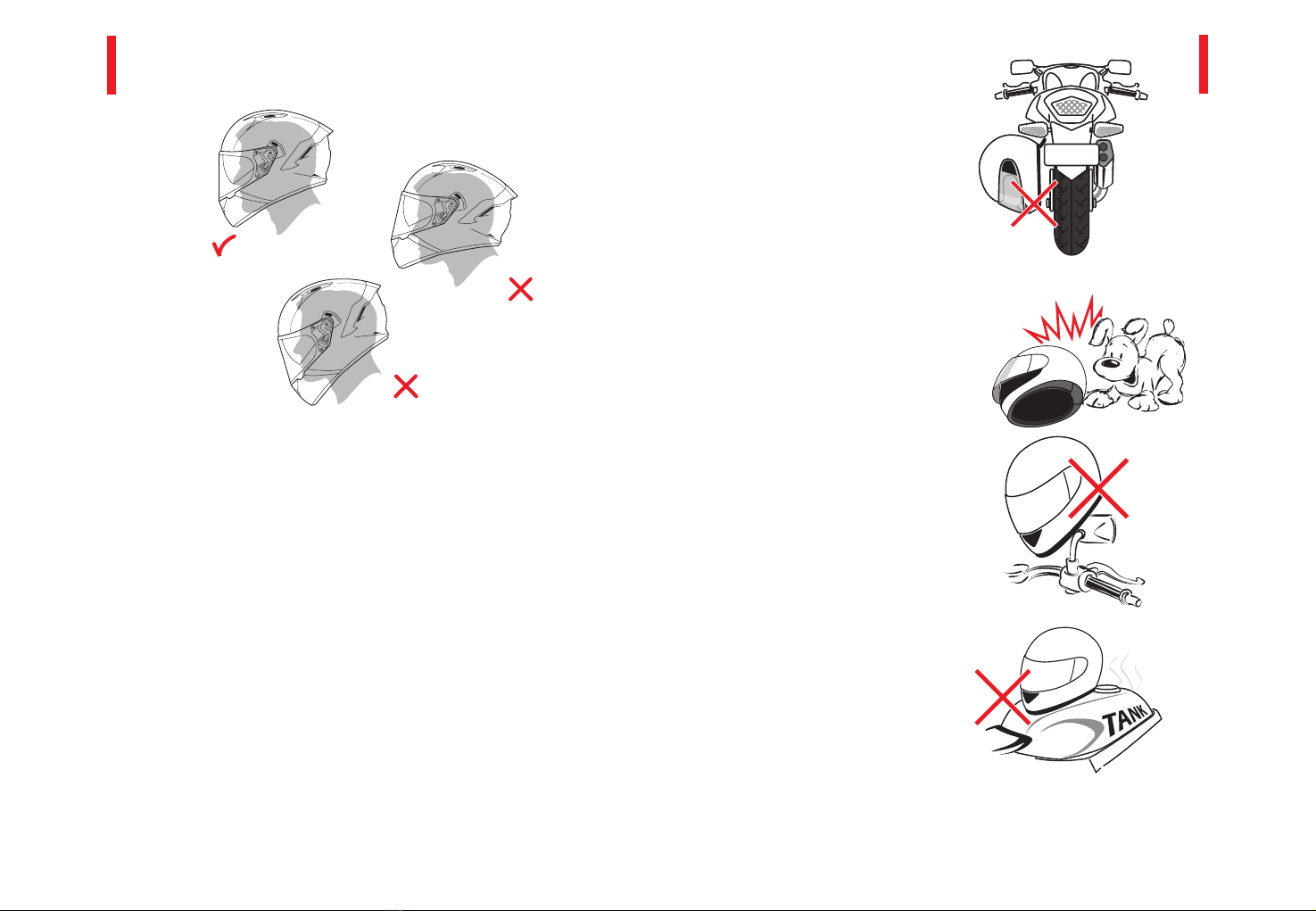
B. Il casco è stato progettato per essere calzato utilizzando il cinturino. Non utilizzare sciarpe
o sottomenti, che potrebbero favorire lo scivolamento del cinturino e lo scalzamento del casco
stesso in caso d’urto.
C. Non devono essere applicati al casco elementi non consigliati dal produttore dello stesso.
D. La calotta non deve essere tagliata né forata.
E. La funzione del casco è quella di ridurre le sollecitazioni sul capo dell’utilizzatore in caso
di urto; questo avviene mediante parziale distruzione e/o deformazione dei suoi componenti
(principalmente calotta esterna e calotta interna in polistirolo). In questo modo parte dell’energia
generata dall’impatto viene assorbita dai componenti del casco, riducendo così le sollecitazioni sul
capo dell’utilizzatore eliminando o limitando la possibilità dell’insorgere di traumi.
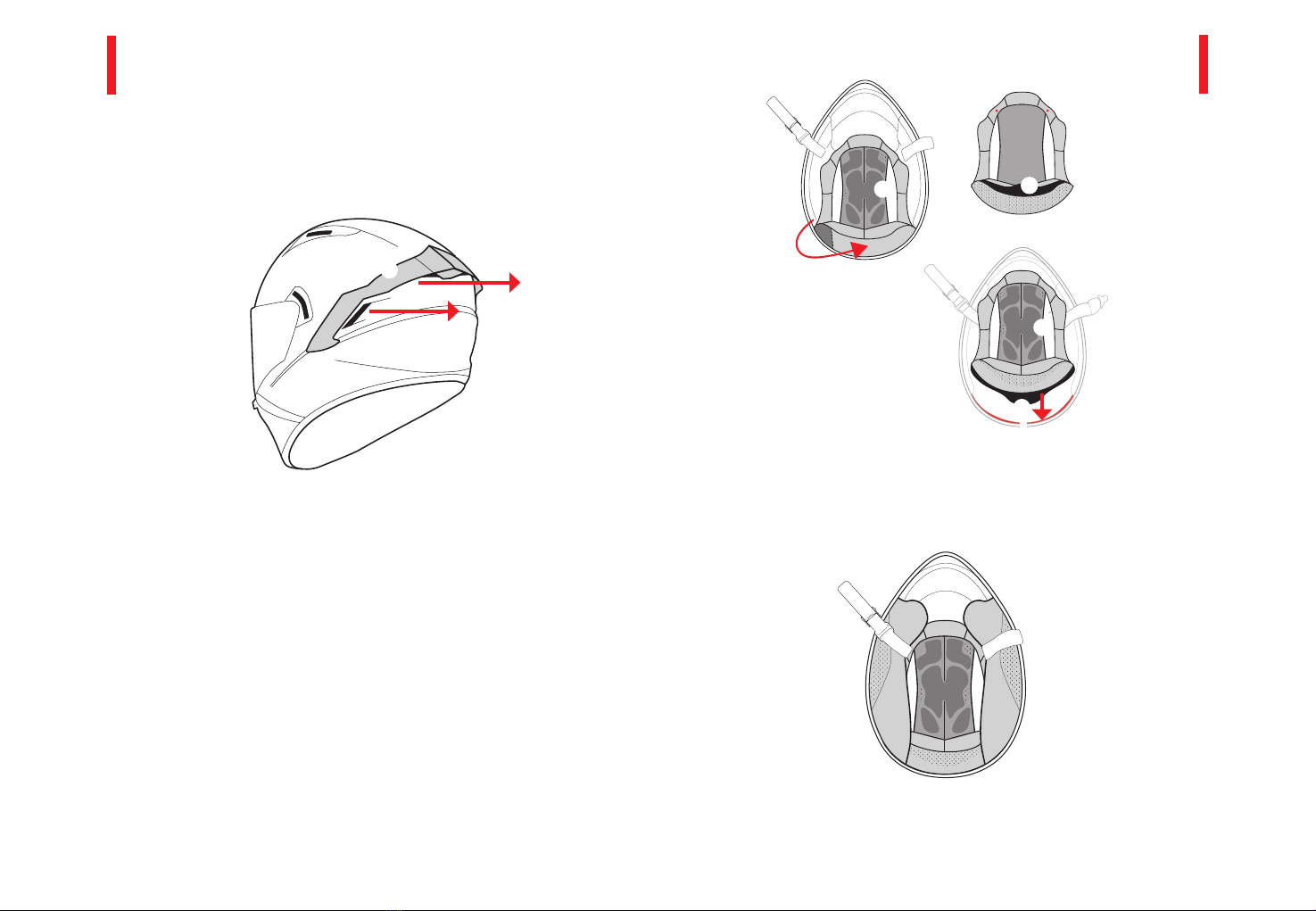
F. L’imbottitura interna è essenziale per la corretta funzionalità del casco. L’integrità della calotta
e dell’interno sono essenziali per garantire le massime prestazioni in termini di sicurezza.
G. Il casco può essere danneggiato con l’applicazione di vernici, adesivi, benzina o altri prodotti
chimici ecc. anche se non presenta danni visibili.
H. Non utilizzare mai un casco che ha subito un urto anche se non appaiono danni visibili; in
caso di impatto il casco dovrà essere sostituito.
- A -
- B -
AVVISO DI SICUREZZA
1. LEGGI QUESTE ISTRUZIONI PRIMA DI
UTILIZZARE IL TUO NUOVO CASCO E
SEGUILE SCRUPOLOSAMENTE.
Il casco è stato studiato e costruito per proteggere
la testa in caso d'impatto, tramite le capacità di
assorbimento dell’urto dei differenti materiali utilizzati.
2. SE IL CASCO SUBISCE UN URTO NON
DEVE PIÙ ESSERE UTILIZZATO
Se il casco subisce un urto non deve più essere
utilizzato. A volte dall’esterno non appaiono danni
visibili ma internamente il materiale potrebbe essere
danneggiato. Il casco è costruito per assorbire un urto
mediate l’alterazione e la parziale distruzione di alcune
sue parti. In caso di urti ulteriori non è in grado di
proteggerti con la massima sicurezza.
3. CORRETTA CALZATA
Attenzione: scegliere correttamente la taglia del tuo
casco è molto importante per la tua sicurezza. Con
l’aiuto del tuo rivenditore autorizzato scegli la corretta
taglia. Per verificare la correttezza della taglia del tuo
casco segui le istruzioni illustrate qui di seguito. Non
utilizzare mai un casco troppo piccolo o troppo grande
per la tua testa.
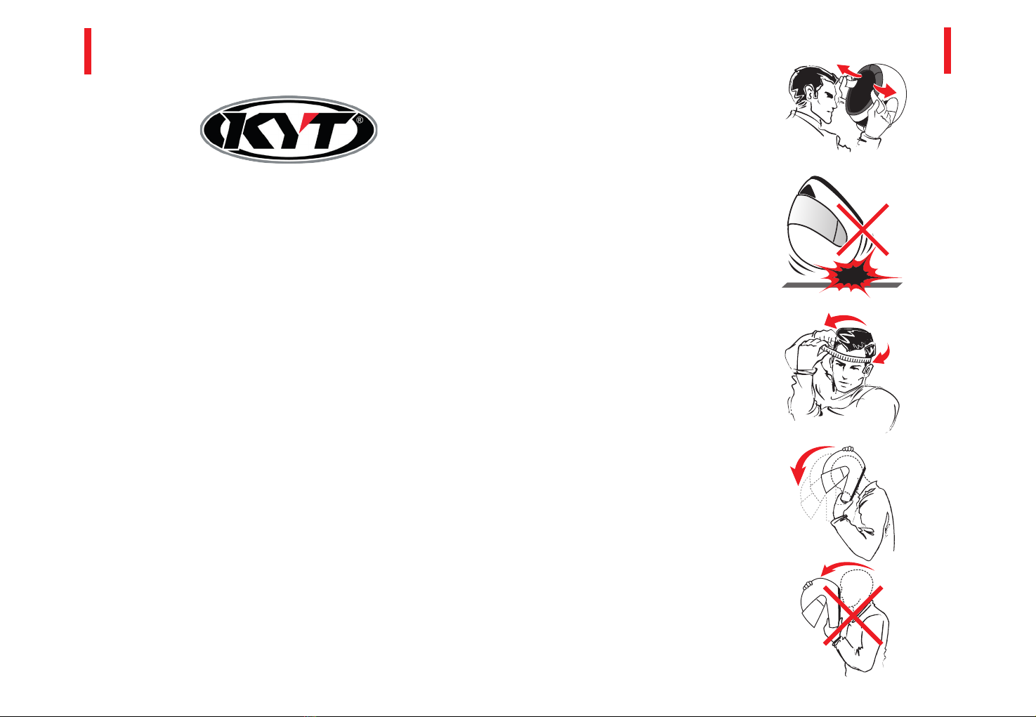
4. COME VERIFICARE LA TAGLIA
Un casco per essere sicuro deve fasciare
completamente la testa. Per verificare la taglia indossa
il casco e scuoti la testa a destra/sinistra e avanti/
indietro: prova a muovere il casco con le mani; se tende
a scivolare significa che è troppo largo e in questo
caso prova una taglia più piccola. Se la pressione sulla
tua testa è fastidiosa e dolorosa, prova una taglia più
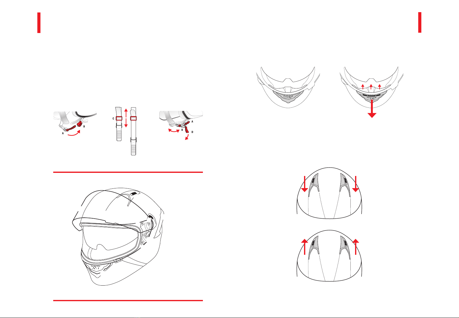
grande. Devi poi effettuare il ROLL-OFF TEST: allaccia
il casco e con una mano prendi il cinturino; con l’altra
mano prova a togliere il casco tirandolo con forza dalla
parte posteriore. Se in questo modo il casco si scalza
la taglia non è corretta. Verifica che tu possa ruotare
liberamente la testa e che la visuale laterale non sia
limitata. Verifica di poter respirare liberamente e che
nulla ostacoli il flusso d’aria all’interno del casco.

4 5
IT IT
5. CALZATA
Non indossare il casco e/o non allacciarlo se questo è calzato troppo indietro (figura B) o in avanti
(figura C); indossa sempre il casco nella posizione corretta (figura A)
6. VISIERA
Il casco è dotato di visiera resistente al graffio e all’appannamento. Per pulire la visiera e
massimizzare l’effetto anti-appannamento utilizzare acqua tiepida e sapone neutro. Evitare di
utilizzare acqua molto clorata. Non utilizzare alcool, benzina o altri solventi e prodotti destinati
alla pulizia dei vetri che potrebbero contenere alcool. Prima di pulire l’interno del casco rimuovere
la visiera. Riapplicarla solo quando i prodotti di pulizia sono completamente evaporati.
ATTENZIONE. Una visiera graffiata va immediatamente sostituita per non comprometterne
la visibilità, soprattutto notturna. Utilizzare le visiere colorate solo per uso diurno. Le visiere
colorate/scure non sono omologate e sono riservate solo all’uso in circuito.
7. PULIZIA E MANUTENZIONE
Pulisci il tuo casco solo con acqua tiepida e poche gocce di sapone neutro o con gli specifici
PRODOTTI PER LA PULIZIA DEL CASCO. Fai asciugare il casco a temperatura ambiente: non
esporlo mai a fonti di calore e non asciugarlo mai con il phon.
8. NON APPORTARE MODIFICHE AL TUO CASCO
Non manomettere il casco. Non tagliare o forare la calotta del tuo casco, non inserire viti, non
verniciarlo. Non apportare alcuna modifica al sottogola. Non rimuovere il bordo inferiore del
casco o quello della visiera: può essere molto pericoloso in caso di incidente. Non modificare
l’interno; in particolare non tagliare o asportare parte del polistirolo perché ridurresti
sensibilmente la possibilità di assopire urti. Utilizza solo parti di ricambio originali.
9. USA IL CASCO CON CURA: NON
APPENDERLO ALLA MOTO DURANTE
LA GUIDA.
Il casco è molto solido ma deve sempre essere
maneggiato con cura. L’urto contro oggetti solidi
o ruvidi può danneggiare la verniciatura o peggio
diminuire la sicurezza del casco. Non viaggiare
con il casco agganciato alla moto perché non solo
rovineresti la verniciatura e la visiera, ma potresti
danneggiare il sottogola. Tienilo sempre lontano
dalla marmitta, dai gas di scarico e dalle fonti di
calore. In estate, durante le soste, proteggilo dai
raggi diretti del sole in particolare se il casco è di
colore scuro o fluo.
10. TIENI IL CASCO LONTANO DALLA
PORTATA DEGLI ANIMALI DOMESTICI
Evita che il casco e i suoi interni entrino in contatto
con un animale domestico; il danno causato
potrebbe rivelarsi irreparabile.
11. POSA IL TUO CASCO IN POSTI
SICURI
Non lasciare il casco sullo specchietto retrovisore
o sul manubrio per evitare di danneggiare l’interno.
12. NON ESPORRE IL CASCO A
SOLVENTI
Non lasciare per lungo tempo il tuo casco
appoggiato al serbatoio; i vapori di benzina che ne
potrebbero fuoriuscire lo danneggerebbero. Non
esporre il casco a solventi, inclusa la benzina o altri
tipi di combustibile, per evitare danni alla visiera, ai
piccoli componenti plastici e ai rivestimenti interni.
FIGURA - A
FIGURA - B
FIGURA - C

6 7
IT IT
SISTEMA DI RITENZIONE A REGOLAZIONE MICROMETRICA — Figura 1
Chiusura del cinturino - sono previsti otto posizioni di fermo che permettono di regolare
agevolmente la chiusura del sistema di ritenzione secondo la conformazione della testa
dell’utilizzatore. 1) Spingere la linguetta in plastica (A) all’interno della guida (B) fino a che il
cinturino aderisca completamente e prema saldamente alla mascella. A chiusura effettuata tirare
energicamente sul cinturino per verificare che il bloccaggio sia stato effettuato correttamente.
2) Nel caso non si riesca ad ottenere un fissaggio corretto, intervenire sulla lunghezza del
cinturino facendo scorrere il nastro nella fibbia (C). Ripetere l’operazione fino ad ottenere un
serraggio corretto del sistema di ritenzione.
Sgancio del cinturino - disimpegnare la linguetta in plastica (A), tirando via il lembo in tessuto (D)
posto sulla linguetta (B). Sganciare il cinturino e sfilare il casco.
ISTRUZIONI D'USO
FIGURA 1
FIGURA 4
FIGURA 5
FIGURA 3FIGURA 2
PRESA D’ARIA FRONTALE MENTONIERA — E — Figura 2/3
Il flusso di aria in ingresso nella parte frontale del casco (mentoniera) può essere regolato agendo
sulla parte centrale della presa d’aria:
- Figura 2: presa d’aria completamente chiusa.
- Figura 3: presa d’aria completamente aperta.
2 31
E
F
F
E
Q
PRESE D’ARIA FRONTALI SUPERIORI —F — Figura 4/5
Il flusso di aria in ingresso nella parte frontale superiore del casco può essere regolato facendo
scorrere il cursore presente sulle prese d’aria stesse:
- Figura 4: Far scorrere i cursori verso l’estremità anteriore, in tal modo le prese d’aria saranno
completamente chiuse.
- Figura 5: Far scorrere i cursori verso l’estremità posteriore, in tal modo le prese d’aria saranno
completamente aperte
E
S
T
V
U
W
Y
X
RG
F

8 9
IT IT
ESTRAZIONE PRESA D’ARIA POSTERIORE —G —Figura 6
L’innovativa presa aria posteriore è stata studiata per migliorare ulteriormente la ventilazione
interna del casco stesso sfruttando i flussi d’aria residui che grazie all’effetto Venturi sono in grado
di generare una depressione nella parte sottostante della stessa garantendo così una notevole
estrazione di aria calda interna e il conseguente mantenimento di una confortevole temperatura.
FIGURA 6
IMBOTTITURA — H— I—J — K
Le imbottiture interne possono essere agevolmente rimosse per essere lavate o sostituite.
Imbottitura centrale interna: CALOTTINA — H— Figura 7/8
Rimozione e Montaggio
La calottina (H) è fissata al casco per mezzo di 2 bottoni automatici (I) e una linguetta
di fissaggio ( J)
Rimozione — Figura 7
Impugnare la parte posteriore della calotta (vicino alla nuca) e sganciare la linguetta di fissaggio
( J) spingendola e contemporaneamente ruotandola verso l’interno. Staccare i bottoni automatici
( I) e rimuovere la calottina interna (H). Porre molta attenzione nella rimozione, facendo leva
sulla parte rigida del bottone e tirando leggermente verso l’interno del casco senza rovinare
il bottone stesso.
Attenzione: per evitare di danneggiare il rivestimento interno, prima di estrarre la
calottina assicurarsi di aver sganciato i bottoni automatici.
Montaggio — Figura 8
Posizionare la calottina (H) all’interno del casco controllando il verso di montaggio.
1) Appoggiare la parte posteriore della calottina alla parte fissa del rivestimento interno avendo
cura che la linguetta di fissaggio (J) sia correttamente inserita nell’apposito alloggiamento (K).
2) Agganciare i bottoni automatici (I). Dopo il fissaggio controllare che la calottina aderisca
correttamente all’interno del casco (imbottitura in polistirolo).
FIGURA 8
FIGURA 7
FIGURA 9
Imbottiture laterali interne: GUANCIALI — L— Figura 9
Rimozione e Montaggio
Rimozione — Figura 10
Impugnare il guanciale (L) nella parte anteriore, spingerlo verso la parte posteriore del casco
e contemporaneamente ruotarlo verso l’interno fino a sganciare i tre bottoni automatici.
L L
G
H
I I
K
J
J
H

10 11
IT IT
FIGURA 10
FIGURA11
FIGURA 12
VISIERA — Q— R— S
La visiera deve essere periodicamente pulita e controllata.
La presenza di sporco e/o di graffi profondi sulla superficie della visiera può essere causa di riflessi
di luce anomali o aberrazioni che diminuiscono la sicurezza di guida. Sostituire immediatamente la
visiera nel caso si riscontrino tali difetti.
Azionamento — Figura 12
La visiera (Q) deve essere azionata agendo solo sulla leva di sollevamento (R). Evitare di azionarla
agendo sulle altre zone in modo da non causare danneggiamenti accidentali (graffi) o sporcare il
campo visivo.
M
O
P
N
Apertura visiera: spingere la visiera leggermente verso l’esterno tramite la levetta di sollevamento
(R) per disimpegnare la linguetta di blocco dalla sede (S) ricavata sotto la guarnizione e sollevarla
verso l’alto.
Chiusura visiera: per bloccare la visiera in posizione di fermo abbassarla fino a che la linguetta sia
bloccata all’interno della sede (S) ricavata sotto la guarnizione.
Sono previste due posizioni di blocco (visiera completamente aperta/chiusa) e quattro posizioni
intermedie. L’azionamento deve sempre essere completato fino alle posizioni di blocco, avvertibili
da un leggero scatto a visiera correttamente bloccata. Per sbloccare la visiera dalle posizioni di
fermo è sufficiente, azionandola come sopra indicato, esercitare una leggera pressione nella fase
iniziale del movimento fino allo sblocco dalla posizione di fermo.
Durante la guida la visiera non deve essere mai lasciata nelle posizioni intermedie;
deve essere sempre bloccata nelle posizioni di fermo.
Rimozione — Figura 13A
1) Sollevare la visiera fino alla posizione di completa apertura.
2) Far scorrere completamente la leva (T). Mantenere in tensione la leva (T).
3) Estrarre la visiera dal meccanismo ruotandola leggermente e contemporaneamente spingendola
verso l’esterno. Ripetere l’operazione sul lato opposto.
Montaggio — Figura 11
Capovolgere il guanciale dalla posizione originaria. Inserire il gancio di fissaggio (M) nell’apposito
foro di aggancio di colore rosso (N). Appoggiare la parte posteriore del guanciale alla parte fissa
del rivestimento interno avendo cura che la linguetta di fissaggio (O) sia correttamente inserita
nell’apposito alloggiamento (P). Spingere il guanciale verso la parte interna del casco e agganciare
i bottoni.
Controllare che il montaggio sia stato eseguito correttamente verificando:
> che il guanciale sia saldamente bloccato in posizione tramite i bottoni automatici
> che il cinturino sia completamente libero all’interno della fessura di passaggio e non
sia rimasto schiacciato sotto il guanciale durante il montaggio.
Solo il corretto bloccaggio del guanciale ed il corretto posizionamento del cinturino
assicurano che il sistema di ritenzione mantenga la sua efficacia.
Nel caso non si riesca a bloccare il guanciale correttamente astenersi dall’usare
il casco.
L
QQ
R
R
S

12 13
IT IT
A
B
FIGURA 13 A-B
Montaggio — Figura 13-B
Per assicurare il miglior funzionamento del sistema di rotazione, prima di procedere
al montaggio della visiera assicurarsi che tutti i particolari (sedi sul casco e superfici
della visiera a contatto con le parti in movimento) siano perfettamente pulite.
Posizionare la visiera come se fosse nella posizione di completa apertura. Posizionare la visiera sul
meccanismo in modo che la sede di rotazione coincida con l’anello di rotazione.
1) Far scorrere la leva (T);
2) Esercitare una leggera pressione in modo da fare aderire gli agganci presenti sulla visiera negli
appositi vani posti sul meccanismo di rotazione.
Ripetere l’operazione sul lato opposto.
A montaggio completato controllare che la visiera sia saldamente vincolata al casco, che ruoti
liberamente e che si blocchi correttamente nelle posizioni di fermo.
Se queste condizioni non fossero verificate ed il meccanismo di rotazione della
visiera non funzionasse correttamente, astenersi dall’usare il casco e rivolgersi
esclusivamente a personale autorizzato.
FIGURA 14
MECCANISMO VISIERA
Rimozione
Dopo aver rimosso la visiera come indicato nei paragrafi precedenti, allentare e rimuovere le viti
(U - V - W); successivamente rimuovere il meccanismo dalla calotta.
Montaggio
I meccanismi non sono intercambiabili. Prima di procedere è necessario identificare
il rispettivo lato di montaggio. Posizionare il meccanismo sulla calotta, inserire le viti e ed
avvitarle.
Dopo il montaggio controllare che i meccanismi siano posizionati correttamente e
fissati saldamente alla calotta. Procedere poi al montaggio della visiera ed alla sua
regolazione come specificato ai paragrafi precedenti.
A montaggio completato controllare che la visiera sia saldamente vincolata al casco, che ruoti
liberamente e che si blocchi correttamente nelle posizioni di fermo.
Se queste condizioni non fossero verificate ed il meccanismo di rotazione della
visiera non funzionasse correttamente, astenersi dall’usare il casco e rivolgersi
esclusivamente a personale autorizzato.
Regolazione — Figura 14
Nel caso in cui, dopo la sostituzione o dopo un uso prolungato del casco, si verificassero
infiltrazioni dai bordi della visiera in posizione completamente chiusa, potrebbe essere necessario
eseguire la regolazione del meccanismo di azionamento della visiera.
Sollevare la visiera fino alla posizione di completa apertura.
Rimuovere la visiera, come specificato nel paragrafo precedente.
Allentare le tre viti (U - V - W) senza rimuoverle e senza smontare il meccanismo.
Traslare in orizzontale l’intero meccanismo e serrare nuovamente le viti.
Ripetere le operazioni sul lato opposto, traslando il meccanismo nella medesima direzione
del precedente. Al termine dell’operazione controllare che la visiera si chiuda e aderisca
perfettamente alla guarnizione.
2
2
1
3
1
T
T
T
U
W
V

14 15
IT IT
VISIERINO SOLARE — X
Azionamento — Figura 15
Il visierino solare deve essere azionato agendo sulla leva (Y).
1) Apertura visierino solare: far scorrere la leva (Y)
2) Chiusura visierino solare: far scorrere la leva (Y) nel verso opposto.
Non utilizzare il visierino solare interno nei giorni di pioggia, quando si guida in
galleria, sottopassi o in qualsiasi momento di luce scarsa.
FIGURA 15
Rimozione — Figura 16
Sollevare la visiera fino alla posizione di completa apertura.
Posizionare il visierino nella modalità di utilizzo. Sganciare il visierino applicando una leggere
pressione verso l’esterno estraendolo dall’apposito alloggiamento (Z) all’interno della calotta.
Ripetere l’operazione sul lato opposto.
Montaggio
Agganciare il visierino applicando una leggere pressione verso l’interno inserendolo nell’apposito
alloggiamento (Z) all’interno della calotta. Ripetere l’operazione sul lato opposto.
FIGURA 16
FIGURA 17
FIGURA 18
PARANASO
Rimozione — Figura 17
Il paranaso è inserito a scatto tra la calotta ed il rivestimento interno della mentoniera; per
rimuoverlo è sufficiente tirare verso l’alto.
Montaggio — Figura 18
Posizionare il paranaso centrandolo sull’apertura visiera, inserendo le linguette tra la calotta ed il
rivestimento mentoniera.
Premere energicamente sul paranaso in corrispondenza delle linguette fino a che il bordo inferiore
del paranaso sia completamente aderente al bordo della calotta.
Se queste condizioni non fossero verificate e il paranaso non fosse aderente al bordo calotta o
comunque posizionato non correttamente, astenersi dall’usare il casco e rivolgersi esclusivamente
a personale autorizzato.
X
2
1
X
X
Y
Z
Y

17
IT
ITALIANO
ENGLISH
FRANÇAIS
ESPAÑOL
DEUTSCH

18 19
EN EN
THANK YOU FOR CHOOSING KYT
Read this instruction carefully before using your helmet. This manual is very important for your
safety and for your helmet life. Helmets have been conceived, designed and manufactured using
the most advanced technologies for motorbike rider’s maximum safety, Helmets have been
created for motorcycle use only and cannot guarantee suitable protection if used for other
purposes or sports. In case of an accident, especially with strong impacts, a helmet will not avoid
all risks of fatal injuries. Do not expose your helmet to intense light sources especially if the color
is fluo as yellow, orange, red or green because the resistance to the light for this kind of color is
very low and it may fade.
Helmet is in compliance with the standards valid in the country of purchase
INFORMATIONS FOR USERS
A. No Helmet can protect the user against any type of crash. Certainly the protection capacity
of the helmet is not endless, some crashes may generate such high stress that even the energy
absorbed by the helmet is not enough to protect the user from injuries. No helmet, even top
quality helmets, can protect the head against any kind of impacts.
B. The helmet is designed to be worn with retention straps securely fasten. Do not wear
scarves or neck guards which could make the strap slide and let the helmet fall off in case of a
crash.
C. Do not stick or glue any element if not recommended by the producer.
D. Do not cut or punch the shell.
E. The function of the helmet is to reduce the stress from user’s head in case of a crash; this
happens through a partial destruction and/or deformation of its components (mostly external
shell and internal polystyrene). In this way, part of the energy generated by the impact, is absorbed
by the helmet components in order to reduce vibrations and stress from the user’s head,
eliminating or limiting the possibility of injures.
F. Inner liner is essential to assure the best helmet functionality. The integrity of the shell and of
the inner are essential to ensure the maximum performance in terms of safety.
G. The helmet may be damaged by using paints, stickers, petrol or cleaning products even if the
damage is not visible.
H. Do not use a helmet that suffered severe blows even though the damage is not readily
visible; if the helmet is damaged it must be replaced.
- A -
- B -
SAFETY WARNING!
1. READ THIS INSTRUCTION CAREFULLY
AND STRICTLY OBSERVE IT BEFORE USING
YOUR NEW HELMET
This helmet has been conceived and manufactured to
protect your head in case of shock thanks to the shock
absorption ability of the different materials used.
2. NEVER USE AGAIN A HELMET THAT HAS
SUFFERED A SHOCK
A helmet that has suffered a shock must not be used
anymore. Sometimes damages are not visible from
the outside however the internal materials may be
damaged. The helmet is designed for shock absorption
by alteration and partial destruction of some parts: in
case of further shock it won’t be able to protect you
with the maximum safety.
3. PROPER WEARING
WARNING! Carefully select the size of your helmet
as it is very important for your safety. Ask for your
authorized dealer’s advice when choosing your helmet
suitable size. In order to check your helmet proper size
follow the instruction below. Never use a helmet that is
too small or too big for your head.
4. HOW TO CHECK YOUR SIZE
A safe helmet should close-fit your head. To check the
size wear your helmet and shake your head left/right
and forward/back. Try to move it with your hands. lf it
slips it means it is too big. Therefore try a smaller size.
lf the pressure on your head bothers or hurts you, try a
bigger size. You must carry out the “ROLL-OFF TEST”:
Fasten your helmet, Hold onto the chin strap with
one hand and using the other one try to take it off by
strongly pulling from the back. lf the helmet comes off,
the size is not correct, Check that you can turn your
head freely and that your side view is not limited. Check
if you can breathe freely and that nothing obstructs the
air flowing inside the helmet.

20 21
EN EN
5. POSITIONING
Always wear it in the proper position (figure A). Do not fasten your helmet if you have positioned
it too much backward (figure B) or forward (figure C).
6. VISOR
The helmet is equipped with a scratch resistant and anti-fog visor . To clean your visor and
maximize the anti-fog effect, use warm water (use demineralized water if available) and neutral
soap. Avoid using water containing too much chlorine. Do not use alcohol, gasoline or other
solvents or window cleaning products which could contain alcohol. Remove the visor before
cleaning the internal of the helmet. Place it back only when the cleaning products are
completely evaporated
WARNING. For safety visibility - especially at night - immediately replace a scratched visor. Use
colored visors only during the day. Darker visors are not homologated and are intended for race
track use only.
7. CLEANING AND MAINTENANCE
Clean your helmet with lukewarm water only (never use hot water) and few drops of neutral
soap or use the special HELMET CLEANING PRODUCTS. Let the helmet dry at ambient
temperature, do not expose to heat sources and never use a blow drier to dry it.
8. DO NOT MODIFY YOUR HELMET IN ANY WAY
Never try to tamper your helmet. Do not cut or drill the shell of your helmet. Do not insert
screws. Do not paint it. Do not modify the chin strap. Do not remove rubber base trim or
the rubber window trim, it could be very dangerous in case of an accident. Do not modify the
comfort padding by cutting or removing the polystyrene as this would greatly reduce the helmet
shock absorption capacity. Use only original spare parts.
9 USE YOUR HELMET CAREFULLY, DO
NOT HANG 1T TO YOUR MOTORCYCLE
WHILE DRIVING
Although your helmet is very strong it must
always be handled with care. Impacts to solid or
rough objects may damage the paint coating or,
even worse, may reduce the helmet safety. Never
ride with your helmet hanging down from your
motorcycle as it would damage the paint coating,
the visor and the chin strap. Always keep it away
from muffler, exhaust gases and heat sources.
In hot weather when you are not riding always
protect it from sunlight, especially if the color of
the helmet is dark.
10. KEEP YOUR HELMET OUT OF THE
REACH OF PETS
Make sure to keep your pets away from the helmet
and its liners. The damage could be irreparable.
11. STORE YOUR HELMET IN A SAFE
PLACE
Do not keep your helmet on the rearview mirror
or handlebar to avoid damages to the comfort
padding.
12. DO NOT EXPOSE YOUR HELMET TO
SOLVENTS
Never keep your helmet on the fuel tank for too
long as the exhausting gasoline fumes may damage
it. Never expose your helmet to solvents such
as gasoline or any other type of fuel in order to
avoid damages to the visor, small plastic parts and
comfort padding.
FIGURE - A
FIGURE - B
FIGURE - C

22 23
EN EN
MICROMETRIC ADJUSTMENT RESTRAINT SYSTEM —Figure 1
Closing the strap – There are eight strap positions that allow to easily adjust the restraint
closure system, depending on the shape of the user’s head.
1) Push the plastic lug (A) in to the guide (B) until the strap is fully secured and pushed firmly
against the jaw . Once closed, pull the strap firmly to check if it is securely fasten.
2) If it is not well secured, adjust the lenght of the strap by moving the band in the buckle (C).
Repeat the operation until the retention system is tightened correctly.
Releasing the strap – Release the plastic lug (A) by pulling (Y) the fabric edge (D) on the lug (B).
Release di strap and slip off the helmet
USER'S INSTRUCTIONS
FIGURE 1
FIGURE 4
FIGURE 5
FIGURE 3FIGURE 2
FRONT AIR INTAKE CHIN —E—Figure 2/3
The flow of incoming air in the front part of the helmet (chin) may be regulated by adjusting on
the middle part of the air intake:
- Figure 2: air intake closed.
- Figure 3: air intake fully open.
2 31
E
F
F
E
Q
FRONT AIR INTAKE UPPER —F—Figure 4/5
The flow of incoming air in the upper front part of the helmet may be regulated by sliding the
cursor on the air intake:
- Figure 4: Slide the cursors forwards to completely close the air intake
- Figure 5: Slide the cursors backwards to completely open the air intake
E
S
T
V
U
W
Y
X
RG
F

24 25
EN EN
REAR AIR VENTS — G—Figure 6
The innovative rear air intake has been designed to further improve ventilation inside the helmet,
using residual air flows that, thanks to the Venturi effect, are able to generate a depression in the
lower part of the helmet, in order to ensure a substantial extraction of the hot air inside it,
consequently maintaining a comfortable temperature.
FIGURE 6
PADDING —H—I—J—K
The inner padding can be easily removed to be washed or replaced.
Inner central padding: INNER SHELL — H— Figure 7/8
Assembly and disassembly
The inner shell (H) is fixed to the helmet through two press studs (I) and a securing tab (J)
Removing the inner padding — Figure 7
Grab the back of the shell (near the nape), release the securing tab (J) by pushing it and, at the
same time, rotate inwards. Snap to open the press studs (I) and remove the inner shell (H). Be
very careful when removing the shell. Press on the rigid part of the stud and pull slightly inwards
the inside of the helmet without damaging the press stud.
Caution: to avoid damages to the inner lining, before removing the inner shell make
sure that all the press studs have been unhooked.
Assembly — Figure 8
Insert the inner shell (E) inside the helmet, check the assembly direction first.
1) Put the back part of the inner shell on the fixed part of the inner liner checking that the
security tab (j) is correctly inserted in its seat (K)
2) Fasten the press studs (I). After fixing the inner shell, make sure the shell is correctly
positioned inside the helmet (polystyrene padding).
FIGURE 8
FIGURE 7
FIGURE 9
Inner side padding: CHEEK PADS —L— Figure 9
Assembly and disassembly
Removing the pads — Figure 10
Grab the cheek pad (L) from the front part, push it to the back part of the helmet and then rotate
inwards until all the press studs are unhooked.
L L
G
H
I I
K
J
J
H

26 27
EN EN
FIGURE 10
FIGURE 11
FIGURE 12
VISOR —Q —R —S
The visor must be periodically cleaned and controlled. If the visor is dirty and/or has bad
scratches on the surface there could be unusual light reflections or deviations, which may
jeopardize safety. Immediately replace the visor if there are these problems.
How to operate — Figure 12
The Visor (Q) has to be operated only by using the lifting lever (R). Do not open it using other
areas to avoid causing accidental damages (scratches) or dirtying the field of vision.
M
O
P
NOpening the visor: push lightly the lifting lever outwards (R), to unlock the tab from its seat (S)
under the gasket and lift it up.
Closing the visor: to lock the visor in position, lower it until the tab is blocked inside its seat (S)
in the gasket.
There are two locking positions: intermediate and visor completely open.
The visor must be opened or closed completely up to the lock position. The visor is correctly
locked into position when it clicks into its seat. To unlock the visor from the lock position just
follow the above procedure, lightly press during initial phase of the movement until the visor is
unlocked.
While riding the motorcycle the visor must never be left in the intermediate
positions; it must always be locked in the locking positions.
Removing the visor — Figure 13A
1) Open the visor until it is completely open.
2) Slide the lever (T) and Keep it in tension (T)
3) Remove the visor from its mechanism by rotating and at the same time pull it outwards. Repeat
the operation on the opposite side.
Assembly — Figure 11
Turn upside down the cheek pads from the original position.
Insert the fixing hook (M) in the red hooking hole (N). Put the back part of the cheek pad on
the fixed part of the inner lining. Verify that the fastening strap (O) is correctly inserted in the
appropriate seat (P). Push the cheek pad to the back part of the helmet and hook the press studs.
Verify that the part was assembled correctly by checking that:
- the cheek pad is firmly locked in position
- the strap is completely free inside the hole and is not blocked under the cheek pad
during assembly.
Only the correct assembly of the cheek pad and the correct positioning of the strap
will assure the proper efficacy of the retention system. During use, the locking lever
must always be fixed in lock position; if it cannot be locked correctly do not use the
helmet.
L
QQ
R
R
S

28 29
EN EN
A
B
FIGURE 13 A-B
Assembly — Figure 13-B
To assure the proper operation of the rotation system of the visor, before fitting the
visor back on, verify that all the parts (seats on helmet, visor surface in contact with
the moving parts) are perfectly clean.
Open the visor completely. Position the visor on the mechanism so that the rotation seat is in-
serted in the rotation ring.
1) Slide the lever (T)
2) Press slightly to stick the hooks on the visor into the slots on the rotation mechanisms
Repeat the operation on the opposite side.
After fitting the mechanism verify that the visor is tightly fixed to the helmet, that it rotates freely
and that it locks correctly into the locking positions.
If this doesn’t happen and the rotation mechanism of the visor doesn’t work correct-
ly, do not use the helmet and contact authorized personnel only.
FIGURE 14
VISOR MECHANISM
Removing the mechanism
After removing the visor as indicated in the paragraphs above, loosen and remove the screws
(U - V - W); then remove the mechanism from the shell.
Fitting the mechanism
The mechanisms are not interchangeable. Before proceeding it is necessary to
identify the correct assembly side. Put the mechanism on the shell, insert the screws
tightening them.
After fitting the parts, verify that the mechanisms are positioned correctly and tightly
fixed to the shell. Then fit the visor and adjust it as specified in the above paragraphs.
After fitting the mechanism verify that the visor is tightly fixed to the helmet, that it rotates freely
and that it locks correctly into the locking positions.
If this doesn’t happen and the rotation mechanism of the visor doesn’t work
correctly, do not use the helmet and contact authorized personnel only.
Adjustment — Figure 14
After replacing the part, or after long use of the helmet you experience infiltration from the
closed visor, it may be necessary to adjust the mechanisms of the visor.
Lift the visor until it is completely open.
Remove the visor, as specified in the previous paragraph.
Loosen the screws (U - V - W) without removing them and without disassembling the mechanism.
Shift horizontally the whole mechanism and tighten the screws.
Repeat the operations on the opposite side by shifting the mechanism on the same direction of
the previous one.
Once finished, check if the visor can be easily closed and if it adheres to the gasket
2
2
1
3
1
T
T
T
U
W
V

30 31
EN EN
NOSE GUARD
Removal — Figure 17
The nose cover is snapped into place between the cap and the inner lining of the chin guard. To
remove it, all you have to do is pull it upwards.
Assembly — Figure 18
Place the nose cover in the middle of the visor’s opening, inserting the tabs between the cap and
the chin guard. Press with force on the nose cover where the tabs are located until the lower
edge of the nose cover is fully adherent to the edge of the cap.
If this doesn’t happen and the nose guard does not adhere to the edge of the shell or is not
positioned correctly, do not use the helmet and contact authorized personnel only.
SUN VISOR —X
How to operate — Figure 15
The Visor has to be operated only by using the lifting lever (Y)
1) Opening the sun visor: Slide the lifting lever (Y)
2) Closing the sun visor: Slide the lifting lever (Y) in the opposite direction
Do not use the sun visor in rainy days, while driving through a tunnel, underpass or
when the light is low.
FIGURE 15
Removing the sun visor — Figure 16
Open the visor until it is completely open.
Put the sun visor in the use mode. Release the sun visor by pushing it outwards and pulling it out
from its seat in the shell. Repeat the operations on the opposite side
Assembly
Hook the sun visor by pushing inwards and inserting it in the correct shell seat, repeat the
operations on the opposite side.
FIGURE 16
FIGURE 17
FIGURE 18
X
2
1
X
X
Y
Z
Y

33
IT
ITALIANO
ENGLISH
FRANÇAIS
ESPAÑOL
DEUTSCH

34 35
FR FR
MERCI D’AVOIR CHOISI KYT
Avant d’utiliser votre casque, lisez avec attention les instructions reportées ci-dessous: elles
sont très importantes pour votre sécurité et pour que votre casque conserve toute son
efficacité dans le temps. Les casques sont étudiés, concus et construits selon les technologies
les plus modernes afin d’offrir un maximum de sécurité au motocycliste. Ils sont créés pour
être exclusivement utilisés par les motocyclistes et ne peuvent par conséquent pas garantir
de protection correcte s’ils sont utilisés dans d’autres buts ou pour pratiquer d’autres sports.
En cas d’accident, spécialement en cas de chocs importants, le casque ne peut, à lui tout seul,
éliminer le risque de lésions mortelles. Ne pas exposer le casque à des sources de lumière
intense, en particulier si la couleur de votre casque est jaune, orange, rouge ou vert fluorescent
car la résistance à la lumière de ces couleurs est peu importante et par conséquent leur teinte
pourrait se décolorer.
Casque conforme aux réglementations en vigueur Dans le pays d’achat.
INSTRUCTIONS POUR L'UTILISATION
A. Aucun casque ne peut protéger de tous les types d’impact. Il est clair que la capacité de
protection du casque n’est pas infinie et que certains heurts peuvent causer des sollicitations
si élevées que même l’énergie absorbée par le casque ne suffit pas à éviter des traumatismes à
l’utilisateur : aucun casque, même de très haute qualité, n’est en mesure d’offrir une protection
telle qu’elle préserve la tête des forces générées par n’importe quel impact subi.
B. e casque a été conçu pour être porté avec la sangle fermée. Ne pas porter avec une écharpe
ou une mentonnière, qui pourraient favoriser le glissement de la sangle et l’enlèvement du casque
en cas d’impact.
C. Aucun élément non conseillé par le fabricant du casque ne doit y être apposé.
D. La calotte ne doit être ni coupée ni percée.
E. La fonction du casque est de réduire les sollicitations sur la tête de l’utilisateur en cas de
heurt ; ceci est rendu possible par la déformation et/ou destruction partielle de ses composants
(principalement la calotte externe et la calotte interne en polystyrène). L’énergie générée
par l’impact est en quelque sorte absorbée par les composants du casque, réduisant ainsi les
sollicitations sur la tête, et éliminant ou limitant la possibilité que s’ensuivent des traumatismes.
F. Le rembourrage interne est essentiel pour la bonne fonctionnalité du casque. L’intégrité de
la calotte et de l’intérieur sont essentiels pour garantir les meilleures prestations en termes de
sécurité.
G. Le casque peut être abimé par l’application de peintures, essence ou autres produits
chimiques… etc, même s’il ne présente pas de dommages visibles.
H. Ne jamais utiliser un casque ayant subi un choc même si aucun dommage apparent n’est
constaté : en cas de heurt, le casque doit être remplacé.
- A -
- B -
AVERTISSEMENT DE SÉCURITÉ!
1. LIRE CES INSTRUCTIONS AVANT
D’UTILISER VOTRE NOUVEAU CASOUE ET
LES RESPECTER SCRUPULEUSEMENT
Ce casque a été étudié et fabriqué pour protéger
votre tête en cas de choc au moyen des capacités
d’absorption du choc des différents matériaux utilizes.
2. UN CASOUE OUI A SUBI UN CHOC NE
DOIT PLUS ÊTRE UTILISÉ
Un casque ayant subi un choc ne doit plus être utilisé:
parfois les dégâts ne sont pas visibles de l’extérieur
mais les matériaux peuvent être endommagés à
l’intérieur. Le casque a été construit pour absorber
un choc au moyen de I ’altération et de la
destruction partielle de certaines de ses parties: en
cas de choc ultérieur il n’est plus en mesure de vous
avec le même dégrée de sécurité.
3. COMMENT CHOISIR CORRECTEMENT
SON CASQUE
ATTENTION ! Choisir correctement la taille de
votre casque est très important pour votre sécurité.
Avec l’aide de votre revendeur autorisé, choisissez la
bonne taille pour votre casque. Afin de vérifier que
la taille est la bonne, suivez les instructions du point
(4). Ne jamais utiliser un casque trop petit ou trop
grand pour vous.
4. COMMENT VERIFIER LA TAILLE
Pour être sûr. un casque doit complètement couvrir
la tête. Pour vérifier la taille, mettez le casque et se-
couez la tête de gauche à droite et d’avant en arrière
: essayez de bouger le casque avec les mains, s’il a
tendance à glisser cela veut dire qu’il est trop grand et
dans ce cas. essayez-en un plus petit. Si la pression sur
votre tête vous gêne ou vous fait mal. essayez-en un
plus grand. Vous devez ensuite effectuer un « ROLL-
OFF TEST » (voir figure B). Attachez le casque et
attrapez la jugulaire d’une main et essayez en meme
temps, avec l’autre, d’enlever le casque en le tirant
fortement par l’arrière. Si, de cette manière, le casque
s’en va, c’est que la taille n’est pas la bonne. Vérifiez
que vous pouvez bouger librement la tête et que
votre vision latérale n’est pas limitée. Vérifier égale-
ment que vous pouvez bien respirer et que rien ne
gêne la circulation de l’air à l’intérieur du casque.

36 37
FR FR
5. PORT DU CASQUE
Ne pas mettre votre casque et/ou l’attacher si et quand il est mis trop en arrière (figure A):
mettez toujours votre casque dans la bonne position (figure B) ou transmettre (figure C).
6. ÉCRAN
Votre casque est équipé d’écran résistant aux rayures et à la buée. Pour nettoyer l’écran
et optimiser l’effet anti-buée, n’utiliser que de l’eau tiède pour le nettoyer, si possible
déminéralisée, avec du savon neutre. Éviter d’utiliser de l’eau très colorée. Ne pas utiliser
d’alcool, d’essence ou autre solvant ou produit destiné au nettoyage des vitres qui pourraient
contenir de l’alcool. Avant de nettoyer l’intérieur du casque, enlever l’écran. Ne le remettre que
quand les produits de nettoyage se sont complètement évaporés.
ATTENTION ! Un écran rayé doit immédiatement être remplacé pour ne pas compromettre la
visibilité, surtout nocturne. N’utiliser les écrans colorés que de jour. Les plus foncés ne sont pas
homologués et sont réservés à une utilisation sur circuit.
7. NETTOYAGE ET ENTRETIEN
Ne nettoyer les casques qu’avec de l’eau tiède (pas chaude !) et quelques gouttes de savon
neutre ou avec des PRODUITS SPÉCIFIQUES POUR LE NETTOYAGE DES CASQUES. Faire
sécher le casque à température ambiante : ne jamais l’exposer à des sources de chaleur et ne
pas le sécher à I ‘aide d’un sèche-cheveux.
8. NE PAS EFFECTUER DE MODIFICATIONS SUR VOTRE CASQUE
Il ne faut jamais effectuer de modifications sur votre casque. Ne pas couper ou trouer la calotte
de votre casque, ne pas y mettre de vis, ne pas le vernir. Ne faire aucune modification sur la
jugulaire. Ne pas enlever le bord inférieur du casque ou celui de la visière: cela pourrait être
très dangereux en cas d’accident. Ne pas en modifier l’intérieur et en particulier ne pas couper
ni enlever une partie du polystyrène car cela réduirait sensiblement les possibilités d’absorption
des chocs. N’utiliser que des pièces de rechange d’origine.
9. UTILISEZ VOTRE CASQUE AVEC
SOIN: NE PAS LE SUSPENDRE A VOTRE
MOTO PENDANT LA CONDUITE
Un casque est très solide mais doit toujours être
manipulé avec soin. Un choc contre des objets
solides ou rugueux pourrait endommager le
vernis ou, pire, diminuer la sécurité du casque.
Ne pas voyager avec le casque accroché à la
moto car, non seulement cela endommagerait
le vernis et la visière, mais cela pourrait
endommager la jugulaire. Faites attention à ce
qu’il soit toujours loin du pot d’échappement, des
gaz d’échappement et des sources de chaleur. En
été, pendant les arrêts, protégez-le des rayons
directs du soleil, en particulier s’il est sombre
10. MAINTENEZ VOTRE CASQUE
HORS DE PORTÉE DES ANIMAUX
DOMESTIQUES
Assurez-vous de garder vos animaux.
Le dommage causé pourrait s’avérer irréparable
11. METTEZ VOTRE CASQUE DANS
DES ENDROITS SURS
Ne pas laisser votre casque sur le rétroviseur
ou sur le guidon afin d’éviter d’en endommager
l’intérieur.
12. NE PAS EXPOSER LE CASQUE A
L’ACTION DE SOLVANTS
Ne pas laisser votre casque sur le réservoir
pendant longtemps, les vapeurs d’essence qui
pourraient s’en échapper l’endommageraient :
ne pas exposer le casque à l’action de solvants
y compris l’essence ou tout autre type de
combustible afin d’éviter d’endommager la
visière, les petits composants en plastique et les
revêtements internes.
FIGURE - A
FIGURE - B
FIGURE - C

38 39
FR FR
SYSTÈME DE RETENUE À RÉGLAGE MICROMÉTRIQUE — Figure 1
Fermeture de la sangle : huit positions d’arrêt sont prévues permettant de régler aisément la
fermeture du système de retenue selon la forme de la tête de l’utilisateur.
1) Pousser sur la languette en plastique (A) à l’intérieur de la glissière (B) jusqu’à ce que la
sangle adhère complètement et appuie fermement sur la mâchoire. Une fois la fermeture
effectuée, tirer fortement sur la sangle pour vérifier que le blocage ait bien été effectué. 2) En
cas d’impossibilité d’obtenir une correcte fixation, intervenir sur la longueur de la sangle en la
faisant coulisser la sangle dans la boucle (C). Répéter l’opération jusqu’à obtenir une fermeture
correcte du système de bouclage.
Ouverture de la sangle : dégager la languette en plastique (A) en tirant le bout en tissu (D) placé
sur la languette (B). Décrocher la sangle et enlever le casque.
INSTRUCTIONS D’UTILISATION
FIGURE 1
FIGURE 4
FIGURE 5
FIGURA 3FIGURE 2
PRISE D’AIR FRONTALE MENTONNIERE —E—Figure 2/3
Le flux d’air dans la partie frontale du casque (mentonnière) peut être régulé en agissant sur la
partie centrale de la prise d’air:
- Figure 2: prise d’air complètement fermée.
- Figure 3: prise d’air complètement ouverte.
2 31
E
F
F
E
Q
PRISE D’AIR FRONTALE SUPERIEURE —F—Figure 4/5
Le flux d’air entrant dans la partie frontale supérieure du casque peut être réglé en déplaçant le
curseur présent sur les prises d’air :
- Figure 4 : Déplacer les curseurs vers l’extrémité antérieure ; de cette façon, les prises d’air se-
ront complètement fermées.
- Figure 5: Déplacer les curseurs vers l’extrémité postérieure ; de cette façon, les prises d’air
seront complètement ouvertes.
E
S
T
V
U
W
Y
X
RG
F
Table of contents
Languages:
Other KYT Motorcycle Accessories manuals
Popular Motorcycle Accessories manuals by other brands

LEXIN
LEXIN LX-R3 user manual

Dowco
Dowco Rally Pack 50030-00 installation instructions

ICON
ICON 37705P installation instructions

BMW Motorrad
BMW Motorrad LEGEND operating instructions

Big Gun Exhaust
Big Gun Exhaust EVO U Series Installation instruction sheet

Shift Power
Shift Power MAGNUM installation manual