L. G. B. 10560 User manual

Entkupplungsgleis
10560

2
D
GB
Vorbemerkungen 4
Asymmetrische Kupplung 4
Symmetrische Kupplung 4
Klauenkupplung 4
Kuppeln 4
Entkuppeln 4
Fernbedientes Elektro-Entkupplungsgleis 10560 5
Montage des Elektro-Entkupplungsgleises 10560 6
Elektrischer Anschluss des Entkupplungsgleises 6
Elektro-Entkupplungsgleis mit Zusatzschalter 12030 6
Dauerentkuppler 10520 6
Der Dauerentkuppler und die symmetrische Kupplung 7
Einbauvorschläge 7
Introductory Notes 8
Asymmetrical Couplers 8
Symmetrical Couplers 8
Knuckle Couplers 8
Coupling 8
Uncoupling 9
Remote Control Electric Uncoupler No. 10560 9
Assembling the Electric Uncoupler 10
Electrical Connection of the Electric Uncoupler 10
Electric Uncoupler with EPL Supplementary Switch No. 12030 10
Constant Uncoupler No. 10520 10
The Constant Uncoupler and Symmetrical Couplers 10
Installation Recommendations 11

3
F
NL
Introduction 12
Attelage asymétrique 12
Attelage symétrique 12
Attelage à griffes 12
Attelage 12
Dételage 12
Rail de dételage électrique télécommandé 10560 13
Montage du rail de dételage électrique 10560 14
Connexion électrique de la voie de dételage 14
Rail de dételage électrique avec interrupteur supplémentaire 12030
14
Dételeur permanent 10520 14
Dételeur permanent et attelage symétrique 15
Recommandations de montage 15
Observaciones preliminares 20
Enganche asimétrico 20
Enganche simétrico 20
Enganche de garras 20
Acoplamiento 20
Desacoplamiento 21
Vía de desenganche eléctrico con control remoto 10560 21
Montaje de la vía de desenganche eléctrico 10560 22
Conexión eléctrica de la vía de desenganche 22
Vía de desenganche eléctrico con interruptor auxiliar 12030 22
Desenganchador permanente 10520 22
El desenganchador permanente y el enganche simétrico 23
Propuestas de montaje 23
Opmerking vooraf 16
Asymmetrische koppeling 16
Symmetrische koppeling 16
Klauwenkoppeling 16
Koppelen 16
Ontkoppelen 16
Op afstand bedienbare elektrische ontkoppelrail 10560 17
Montage van de ontkoppelrail 10560 18
Elektrische aansluiting van de ontkoppelrail 18
Elektrische ontkoppelrail met schakelaar 12030 18
Vast ontkoppelstuk 10520 18
Het vaste ontkoppelstuk en de symmetrische koppeling 19
Inbouwvoorbeelden 19
Osservazioni preliminari 24
Aggancio asimmetrico 24
Aggancio simmetrico 24
Aggancio a ganascia 24
Agganciamento 24
Sganciamento 25
Binario di sganciamento elettromagnetico azionato a distanza 10560
25
Montaggio del binario di sganciamento elettromagnetico 10560
26
Collegamento elettrico del binario di sganciamento 26
Binario di sganciamento elettromagnetico con commutatore
aggiuntivo 12030 26
Sganciatore permanente 10520 26
Lo sganciatore permanente e l’aggancio simmetrico 27
Suggerimenti di installazione 27

4
Vorbemerkungen
Für die LGB gibt es zwei Kupplungssysteme:
1. Hakenkupplung (asymmetrisch oder symmetrisch)
2. Klauenkupplung
Werksseitig sind die LGB-Fahrzeuge mit der asymmetri-
schen Hakenkupplung ausgerüstet. Jedem Wagen liegt
ein zweiter Kupplungshaken bei, damit dieser auf die
symmetrische Kupplung aufgerüstet werden kann.
Asymmetrische Kupplung
Die LGB-Fahrzeuge ab Baujahr 1980 haben an einer
Seite einen Kupplungshaken, der nach allen Seiten
schwenkbar gelagert ist. Der Vorteil dieser asymmet-
rischen Kupplung: Einzelne Wagen können aus einem
Zugverband problemlos herausgenommen werden.
Symmetrische Kupplung
Die LGB-Fahrzeuge ab Baujahr 1980 kann man leicht mit
einem zweiten Kupplungshaken ausrüsten. So entsteht
eine symmetrische Kupplung. Ihre Pluspunkte:
1. sicheres Kuppeln auch auf uneben verlegten Gleisen
2. keine ungewollten Entkupplungen
3. keine Schwierigkeiten bei Kehrschleifen.
Klauenkupplung
Die LGB-Klauenkupplung 64192 (2019/2) ist als Zurüstteil
lieferbar. Sie ist den in Amerika gebräuchlichen Auto-
matikkupplungen nachgebildet und voll funktionstüchtig.
Das sind ihre Besonderheiten:
1. beweglicher Kupplungskopf, dadurch perfektes
Kuppeln auch in Gleisbögen möglich
2. Züge lassen sich mit der Klauenkupplung einwandfrei
schieben.
Die Klauenkupplung ist eine symmetrische Kupplung.
Sie wurde für vierachsige LGB-Wagen ab Baujahr 1980
konstruiert. Ihre nachträgliche Anbringung an diesen
Fahrzeugen ist sehr einfach. An zweiachsigen Wagen
kann es mit der Klauenkupplung beim Einbau (die Mittel-
puffer an den Fahrzeugen müssen entfernt werden) und
im Schiebebetrieb Probleme geben.
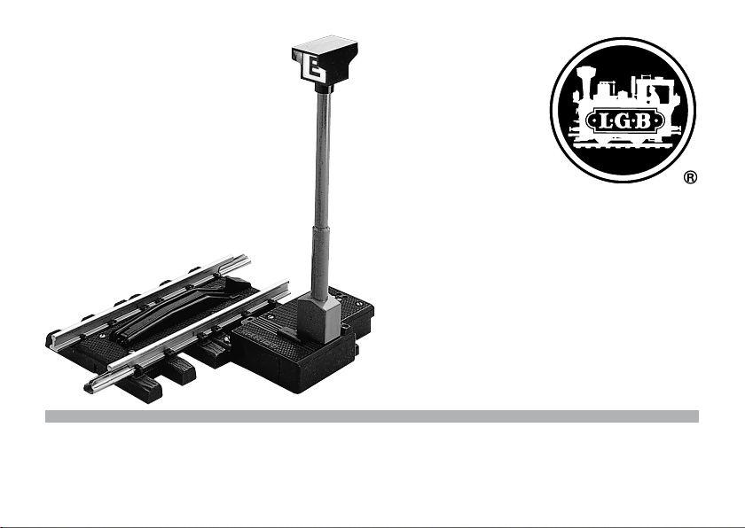
Die Klauenkupplung lässt sich mit dem Elektro-Entkupp-
lungsgleis 10560 einwandfrei entkuppeln.
Kuppeln
Das Kuppeln geschieht durch einfaches Aneinander-
schieben der Fahrzeuge, wobei der Kupplungshaken
bzw. die Klauenkupplung spielend leicht in die Kupplung
des anzukuppelnden Fahrzeugs einrasten.
Entkuppeln
Das vorbildgetreue Entkuppeln von LGB-Fahrzeugen
kann mit einem ferngesteuerten Elektro-Entkupplungs-
gleis 10560 oder mit dem Dauerentkuppler 10520
erfolgen.

5
Fernbedientes Elektro-Entkupplungsgleis 10560
Die zu entkuppelnden Fahrzeuge werden mit ihren
Kupplungen über der Entkupplungsbohle zum Halten ge-
bracht. Durch Tastendruck am Stellpult 51750 hebt sich
die Entkupplungsbohle, der Haken der Kupplung senkt
bzw. die Klauenkupplung öffnet sich, und die Entkupp-
lung ist vollzogen.
Die Entkupplung erfolgt auch, wenn die zu entkup-
pelnden Fahrzeuge langsam in Rangierfahrt über die
Kupplungsbohle gezogen werden.
Das Bild 1 zeigt die Funktionselemente des Elektro-
Entkupplungsgleises 10560:
1. Stellhebel des Elektroantriebes
2. Kabelklemmen für Fernbedienungsanschluss an
Stellpult
3. Kabelklemmen für Lichtanschluss des Mastes
4. Beleuchteter Mast
5. Entkupplungsbohle
Das Entkupplungsgleis hat eine Länge von 150 mm und
entspricht damit einem halben geraden Gleis (10150). Der
beleuchtete Mast zeigt die genaue Position der Entkupp-
lungsbohle an, was vor allem dann sehr hilfreich ist, wenn
ein Elektro-Entkupplungsgleis auf einer großen Anlage
weiter entfernt vom Stellpult eingebaut worden ist.

6
Montage des Elektro-Entkupplungsgleises 10560
Bild 2 zeigt die notwendigen Handgriffe:
1. Stellschieber nach links drücken, wobei sich die
Kupplungsbohle hebt.
2. Lichtmast aufstecken, wobei die Stromverbindung
zum Lichtmast automatisch hergestellt wird.
Elektrischer Anschluss des Entkupplungsgleises
Bild 3 zeigt die notwendigen Kabelverbindungen vom
Trafo zum Stellpult 51750 und von dort zum Elektro-
Entkupplungsgleis.
Elektro-Entkupplungsgleis mit Zusatzschalter 12030
Der Weichenzusatzschalter 12030 kann auch an das
Elektro-Entkupplungsgleis angesteckt werden. Je nach
Anschluss ergeben sich damit folgende zusätzliche
Funktionen (Bild 4):
a Anschluss einer Rückmeldelampe in einem Gleisbild-
stellpult.
b Anschluss des Entkupplungsmastes zur Ausleuchtung
des „E“-Symbols nur bei gehobener Kupplungsbohle.
Dauerentkuppler 10520
Der Dauerentkuppler 10520 kann an jeder beliebigen
Stelle der Gleisanlage auf die Schwellen gerader oder
gebogener Gleise aufgesteckt werden. Beim langsamen
Überfahren des Dauerentkupplers senkt sich der Kupp-
lungshaken und die Entkupplung erfolgt.
Der Einbau des Dauerentkupplers wird vorzugsweise an
den Stellen der Gleisanlage erfolgen, wo ständig entkup-
pelt werden muss, zum Beispiel in einem Endbahnhof,
wo die Lok immer vom Zug abgekuppelt wird, da sie sich
zur Rückfahrt über das Umfahrgleis an das andere Ende
des Zuges setzen muss.

7
Der Dauerentkuppler und die symmetrische Kupplung
Wird die symmetrische Kupplung verwendet, muss man,
um den Entkupplungsvorgang zu vollziehen, zwei Dau-
erentkuppler hintereinander einbauen, da ja gleichzeitig
zwei Kupplungshaken abgesenkt werden müssen. Das
gilt auch bei Verwendung eines Elektro-Entkupplungs-
gleises, bei dem zusätzlich ein Dauerentkuppler 10560
eingebaut werden muss, um das Absenken beider Kupp-
lungshaken der symmetrischen Kupplung und damit das
einwandfreie Entkuppeln zu gewährleisten.
Einbauvorschläge:
Entkupplungsgleise werden vorzugsweise in Bahnhofs-
und Abstellgleisen eingebaut. Das Bild 5 zeigt einige
Einbaubeispiele für Elektro-Entkupplungsgleise 10560
(und zusätzlich für Dauerentkuppler 10520, sofern sym-
metrische Kupplungen verwendet werden).
Entkuppler müssen so in Weichenstraßen eingebaut
werden, dass die Fahrzeugbegrenzung abgekuppelter
Fahrzeuge nicht in das Lichtraumprofil benachbarter
Gleise ragt. Rangieren, und damit auch das Entkuppeln,
sollte stets in langsamer Fahrt erfolgen. Zum Entkuppeln
werden die Fahrzeuge langsam über die Entkuppler
gezogen. Beim Schieben über Entkuppler würden die
Kupplungen wieder einrasten.

8
Introductory Notes
There are two coupling systems for LGB trains:
1. Hook couplers (symmetrical and asymetrical).
2. Knuckle couplers
LGB rolling stock comes equiped from the factory with
asymetrical hook couplers. Every car also comes with
an extra hook coupler which can be installed to allow
symmetrical coupling.
Asymmetrical Couplers
LGB rolling stock produced after 1980 have a single
coupler on one side that pivots freely from side to side.
The advantage of this asymme trical coupler arrange-
ment is that it allows you to easily remove a single car
from the middle of a train.
Symmetrical Couplers
LGB rolling stock produced after 1980 can easily be
fitted with a double coupler system. In this way, you can
create a symmetrical coupling system. Symmetrical cou-
pling makes it easier to execute complicated switching
and coupling operations. Since the cars have hooks
at both ends, they can be coupled together no matter
which direction they are running. Also, symmetrical
couplings are very secure, even on unevenly-laid track.
Knuckle Couplers
The LGB knuckle coupler is available as a replacement
part. It is usually used by American-prototype modelers
to reproduce automatic coupling operations of U.S.
railroads while maintaining compatibility with the LGB
program. The moveable coupler heads on LGB knuckle
couplers allow perfect coupling, even in curves. Also,
trains can be pushed easily with LGB knuckle couplers.
The knuckle coupler is a symmetrical coupler, that is,
a knuckle coupler must be installed on both ends of
a car. LGB knuckle couplers are designed for simple
installation on all four-axle LGB cars produced after
1980. When knuckle couplers are installed on two-axle
cars, the couplers may cause problems during switching
operations.
The knuckle couplers work perfectly with LGB’s electric
uncoupling Track No. 10560.
Coupling
No matter which LGB coupling system is use, LGB rolling
stock can be easily coupled by lightly touching the cars
to be coupled together.

9
Uncoupling
Prototypical uncoupling of LGB rolling stock can be
accomplished with our remotely-controlled electric
uncoupler No. 10560 or with LGB’s constant uncoupler
No. 10520.
Remote Control Electric Uncoupler No. 10560
You can uncouple LGB rolling stock by bringing them to
a stop via the uncoupling plank of LGB remote control
electric uncoupler No. 10560. When a rocker switch is
pressed on LGB’s switch control box 51750 (or the older
No. 50750), the uncoupling plank is raised, the hook part
of the coupler is lowered (or, if you have LGB’s knuckle
coupler, one side is released) and your LGB cars are
uncoupled.
Uncoupling is also accomplished by slowly moving the
rolling stock you want to uncouple down the shunting
track and over the electric uncoupler. Fig. 1 shows the
components of the electric uncoupler:
1. Lever between signal drive and uncoupling plank
2. Cable terminals for remote control with a switch
control box
3. Cable terminals for connection of the mast light
4. Light mast
5. Uncoupling plank
The electric uncoupler is 150 mm long and corresponds
to one half of a regular LGB No. 10150 straight track
piece. The illuminated light mast shows the precise posi-
tion of the uncoupling plank, which is very helpful when
the electric uncoupler is installed far away from the
switched control box – on a large layout, for instance.

10
Assembling the Electric Uncoupler
Fig. 2 shows the necessary procedure:
1. Push the slider to the left to raise the uncoupling
plank.
2. Plug in the light mast. The power connection to the
light mast will automatically be established.
Electrical Connection of the Electric Uncoupler
Fig. 3 shows the correct cable connections from the va-
riable speed control to the switch control box No. 51750
(or 50750), and to and from the electric uncoupler.
Electric Uncoupler with EPL Supplementary
Switch No. 12030
The EPL supplementary switch No. 12030 can also be
attached to the electric uncoupler. Depending on the
connection, it can be used to (see Fig. 4):
a) Automatically turn on a control panel light when the
uncoupling plank is raised.
b) Automatically turn on the “E“ mast light when the
uncoupling plank is raised.
Constant Uncoupler No. 10520
The constant uncoupler No. 10520 can be installed in the
ties of any straight or curved track. When the train is run
slowly over the constant uncoupler, the coupler hook is
lowered and uncoupling occurs. You should place the
constant uncoupler in a position on your track layout
where you want permanent uncoupling, for example, in
a terminal station where the locomotive always has to
be uncoupled from the train in order to move to the front
of the train again.
The Constant Uncoupler and Symmetrical Couplers
When you are using symmetrical couplers, you need to
install two constant uncouplers end to end. This is be-
cause the coupler hooks on both cars must be lowered
simultaneously for uncoupling to be successful. This
also holds true when using the electric uncoupler, which
must be used in conjunction with a constant uncoupler
so that both coupler hooks on the symmetrical couplers
are lowered at the same time, ensuring faultless uncou-
pling.

11
Installation Recommendations
Uncoupling tracks works best when used in train station
tracks and shunting tracks. Fig. 5 shows some examples
of installation of the electric uncoupler (including the
arrangement where the electric uncoupler works with
constant uncoupler to unclouple trains with symmetrical
couplers).
Uncouplers should be installed as shown in the swit-
ching tracks, so that the uncoupled cars do not interfere
with other tracks. Switching and uncoupling should be
done while the train is moving slowly or stopped. After
uncoupling, the coupler hooks will return to their original
positions.

12
Introduction
LGB a deux systèmes d’attelage:
1. attelage à crochet
2. attelage à griffes.
Les véhicules LGB construits à partir de 1980 ont, sur
le côté, un crochet. Chaque wagon est livré avec un
deuxième crochet d’attelage pour permettre d’équiper le
wagon d’un attelage symétrique.
Attelage asymétrique
Les véhicules LGB construits à partir de 1980 ont, sur le
côté, un crochet d’attelage pivotant dans tous les sens.
Avantage d’un attelage asymétrique: On peut, sans prob-
lème, enlever un wagon du train déjà formé.
Attelage symétrique
Les véhicules LGB construits à partir de 1980 peu-
vent être facilement équipés d’un deuxième crochet
d’attelage. Ce qui donne un attelage symétrique.
Avantages:
1. Attelage facile même sur voies posées sur une sur-
face non-plane.
2. Pas de dételage imprévu.
3. Passage sans problèmes des boucles de retour.
Attelage à griffes
L’attelage à griffes LGB peut être monté ultérieurement.
Fonctionnant parfaitement, il est une reproduction de
l’attelage automatique employé aux rités Etats-Unis.
Voici ses particularités:
1. Tête d’attelage mobile permettant un attelage parfait,
même en ligne courbe.
2. Grâce à l’attelage à griffes, il est facile de pousser les
trains.
L’attelage à griffes est un attelage asymétrique. Il a été
conçu pour les wagons LGB à quatre essieux, construits
à partir de 1980. Cependant, il est très simple d’en
équiper ultérieurement les wagons. Des problèmes de
montage et en poussée peuvent survenir (les tampons
centraux du véhicules doivent être enlevés) avec les
wagons deux essieux. Le rail de dételage électrique
10560 permet de dételer, sans problème, I’attelage à
griffes.
Attelage
Une simple poussée des wagons suffit pour atteler.
La griffe de l’attelage s’enclenche facilement dans
l’attelage du véhicule à atteler.
Dételage
Le rail de dételage télécommandé 10560 ou par le
dételeur permanent 10520 permet le dételage (reproduc-
tion fidèle) des véhicules LGB.

13
Rail de dételage électrique télécommandé 10560
Véhicules et attelages sont amenés à s’arrêter par
le madrier de dételage. En appuyant sur la touche du
pupitre de commande 51750, le madrier se soulève, le
crochet d’attelage s’abaisse ou selon le cas la griffe
s’ouvre.
L’opération dételage est terminée. Le dételage peut être
également effectuer en tirant au ralenti, dans le sens
de manoeuvre, les véhicules à dételer sur le madrier de
dételage.
La Img. 1 montre les éléments permettant le fonctionne-
ment du rail de dételage 10560:
1. levier de commande électrique
2. bornes de câble pour la télécommande au pupitre de
commande
3. bornes de câble pour le raccord lumière du pylône.
4. pylone éclairé
5. madrier de dételage
Le rail de dételage est long de 150 mm, soit la moitié
d´un rail droit (10150). Le pylône éclairé donne la position
exacte du madrier de dételage ce qui est particulière-
ment appréciable surtout sur un grand réseau qui peut
avoir un rail de dételage électrique éloigné du pupitre de
commande.

14
Montage du rail de dételage électrique 10560
Le Img. 2 montre la façon de procéder:
1. Appuyer le curseur de réglage vers la gauche. Le
madrier de dételage doit se soulever.
2. Monter le pylône d’éclairage. Celuici est branché
automatiquement sur le courant.
3. Comment changer une ampoule.
Connexion électrique de la voie de dételage
L’image 3 montre les connexions de câbles nécessaires
allant du transformateur au pupitre de commande 51750,
puis de là à la voie de dételage électrique.
Rail de dételage électrique avec interrupteur sup-
plémentaire 12030
L’interrupteur d’aiguillages suplémentaire 12030 peut
être branché sur le rail de dételage. Le branchement
permettra les fonctions supplémentaires suivantes
(Img. 4):
a) branchement d’une lampe de réplique sur le pupitre
de commande.
b) branchement du pylône de dételage. Le symbole ”E“
allumé signale le madrier soulevé.
Dételeur permanent 10520
Le dételeur permanent 10520 peut être installé à
n’importe quel endroit du réseau que ce soit sur un rail
courbe. Le dételage s’effectué en passant au ralenti sur
le dételeur qui abaisse alors le crochet.
Il est préférable de monter le dételeur permanent là
où le dételage est constamment employé, par exemple
dans une gare où la locomotive doit être détachée du
train pour être remise en queue de train.

15
Dételeur permanent et attelage symétrique
L’attelage symétrique nécessite deux dételeurs perma-
nents puisque, pour le dételage, ce sont deux crochets
qui doivent être abaissés simultanément. Il en va de
même pour l’utilisation d’un rail de dételage qui néces-
site en plus un dételeur permanent 10560 pour assurer le
bon abaissement des 2 crochets d’attelage symétrique.
Recommandations de montage
Il est préférable de monter les rails de dételage dans
les gares ou sur les voies de garage. Il est possible de
s’inspirer du Img. 5 montrant quelques exemples de
montage du rail de dételage électrique 10560 (et, en
cas d’utilisation d’un système d’attelage symétrique, du
dételeur permanent 10520).
Les dételeurs doivent être montés sur les voies de
triages de telle sorte que la longueur des véhicules non-
attelées ne dépasse pas le gabarit d’espace libre des
voies avoisinantes. Manoeuvres et dételages sont des
opérations qui se font au ralenti en tirant lentement les
véhicules sur le dételeur. En poussant sur le dételeur, ils
seraient ré-atteler.

16
Opmerking vooraf
Bij LGB zijn er twee koppelingssystemen:
1. Haakkoppeling (asymmetrisch of symmetrisch)
2. Klauwkoppeling
Af fabriek zijn de LGB voertuigen met de asymmetrische
haakkoppeling uitgevoerd. Bij elke wagen is een tweede
koppelingshaak bijgevoegd waarmee deze dan met
symmetrische koppelingen kan worden uitgerust.
Asymmetrische koppeling
De LGB voertuigen vanaf bouwjaar 1980 hebben aan één
zijde een koppelingshaak die naar alle kanten zwenk-
baar gelagerd is.
Het voordeel van deze asymmetrische koppeling: de
wagen kan gemakkelijk uit de trein genomen worden.
Symmetrische koppeling
De LGB voertuigen vanaf bouwjaar 1980 kan men
eenvoudig van een tweede koppelingshaak voorzien.
Op die wijze ontstaat een symmetrische koppeling. De
pluspunten:
1. betrouwbaar koppelen ook op niet vlak verlegde
railstukken.
2. geen ongewilde ontkoppeling.
3. geen problemen in keerlussen.
Klauwenkoppeling
De LGB klauwenkoppeling 64192 (2019/2) is als toebe-
horen leverbaar. Het is een volledig werkende kopie van
de in Amerika gebruikelijke automatische koppeling. Dit
zijn de bijzonderheden:
1. beweegbare koppelingskop waardoor perfect koppel-
end ook in bogen.
2. treinen laten zich met de klauwenkoppeling pro-
bleemloos duwen.
De klauwenkoppeling is een symmetrische koppeling.
Ze werden vanaf 1980 voor de vier-assige LGB wagens
geconstrueerd. Het nadien aanbrengen op deze wagens
is zeer eenvoudig. Aan twee-assige wagens kunnen er
met de klauwkoppeling bij het inbouwen (de midden-
buffer moet verwijderd worden) en bij het duwbedrijf
problemen ontstaan. De klauwkoppeling laat zich met de
elektrische ontkoppelrail 10560 probleemloos ontkop-
pelen.
Koppelen
Het koppelen gebeurd door de wagens eenvoudig tegen
elkaar aan te duwen waarbij de koppelingshaak resp. de
klauwkoppeling gemakkelijk in de koppeling van het aan
te koppelen voertuig klikt.
Ontkoppelen
Het voorbeeldgetrouw ontkoppelen van LGB voertuigen

17
kan met de op afstand bestuurbare ontkoppelrail 10560
of met het vaste ontkoppelstuk 10520 gebeuren.
Op afstand bedienbare elektrische ontkoppelrail 10560
De te ontkoppelende voertuigen worden met hun kop-
pelingen boven de ontkoppelbrug tot stilstand gebracht.
Door op de toets van het bedieningspaneel 51750 te
drukken gaat de ontkoppelbrug omhoog, de haak van de
koppeling lost zich resp. de klauwenkoppeling opent zich
en de ontkoppeling is een feit.
De ontkoppeling werkt ook als de te ontkoppelende
voertuigen langzaam met rangeersnelheid over de
ontkoppelbrug getrokken worden.
Afb. 1 toont de functionerende delen van de elektrische
ontkoppelingrail 10560.
1. stelhendel van de elektrische aandrijving.
2. draadklemmen voor de aansluiting bedieningspaneel.
3. draadklemmen voor de lichtaansluiting van de mast
4. verlichte mast
5. ontkoppelbrug
De ontkoppelrail heeft een lengte van 150 mm wat ove-
reenkomt met een halve rechte rail (10150). De lichtmast
geeft de positie van de ontkoppelbrug aan, hetgeen een
belangrijk hulpmiddel is als de ontkoppelrail op een gro-
te baan verder van het bedieningspaneel is ingebouwd.

18
Montage van de ontkoppelrail 10560
Afb. 2 toont de noodzakelijke handelingen:
1. stelhendel naar links drukken waardoor de ontkoppel-
brug omhoog komt.
2. lichtmast er insteken waardoor de stroomverbinding
naar de lichtmast automatisch gemaakt wordt.
Elektrische aansluiting van de ontkoppelrail
Afb. 3 toont de noodzakelijke draadverbindingen van de
trafo naar het bedieningspaneel 51750 en daarvandaan
naar de ontkoppelrail.
Elektrische ontkoppelrail met schakelaar 12030
De schakelaar 12030 kaan ook op de elektrische ontkop-
pelrail gestoken worden. Afhankelijk van de aansluiting
zijn daarmee de volgende extra functies (afb. 4) mogelijk:
a aansluiten van een terugmelding in het bedieningspa-
neel
b aansluiten van de lichtmast voor het uitlichten van het
“E”-symbool als de ontkoppelbrug omhoog staat.
Vast ontkoppelstuk 10520
Het vaste ontkoppelstuk 10520 kan op elke gewenste
plaats op de baan, op de biels van een recht of gebogen
railstuk worden gestoken. Door er langzaam overheen
te rijden lost de koppelingshaak en de ontkoppeling is
een feit. Het vaste ontkoppelstuk bijvoorkeur inbouwen
op een plaats waar ten allen tijde een ontkoppeling moet
plaats vinden. Bij voorbeeld in een kopstation waar de
loc altijd van de trein losgekoppeld moet worden omdat
deze voor de terugreis, via het omrijspoor aan de andere
kant van de trein gekoppeld moet worden.

19
Het vaste ontkoppelstuk en de symmetrische koppeling
Als de symmetrische koppelingen worden gebruikt dient
men, om de ontkoppeling volledig te laten verlopen,
twee vaste ontkoppelstukken achter elkaar inbouwen
aangezien er twee koppelingshaken gelijktijdig gelost
moeten worden. Dat geldt ook bij het toepassen van
de elektrische ontkoppelrails waarbij er een extra vast
ontkoppelstuk 10520 ingebouwd dient te worden om het
lossen van de beide koppelingshaken van de symme-
trische koppelingen te bewerkstellen.
Inbouwvoorbeelden:
Ontkoppelrails worden bijvoorkeur in stations- en
opstelsporen ingebouwd. De afb. 5 toont enige inbouw
voorbeelden voor de elektrische ontkoppelrail 10560 ( en
het extra ontkoppelstuk 10520, voor zover symmetrische
koppelingen worden gebruikt).
Ontkoppeldelen dienen dusdanig in de wisselstraten
in gebouwd te worden zodat ontkoppelde wagens zich
niet binnen het “profiel van vrije ruimte” van een naast
liggend spoor bevinden. Het rangeren en daarmee ook
het ontkoppelen dient altijd met een lage snelheid te
gebeuren. Om te ontkoppelen worden de voertuigen
langzaam over het ontkoppeldeel getrokken. Bij het
duwen over het ontkoppeldeel klikken de koppelingen
weer in elkaar.

20
Observaciones preliminares
Para la LGB hay dos sistemas de enganche:
1) Enganche de gancho (asimétrico o simétrico)
2) Enganche de garras
Los vehículos LGB vienen de fábrica equipados con
el enganche de gancho asimétrico. A cada coche se
adjunta un segundo gancho de enganche para poder
convertir el gancho asimétrico en uno simétrico.
Enganche asimétrico
Los vehículos LGB a partir del año de fabricación 1980
incorporan en un lado un gancho de enganche que está
apoyado de tal modo que pueda bascular hacia todos
los lados. La ventaja de este enganche asimétrico: Los
distintos coches se pueden desenganchar sin ningún
problema de un convoy.
Enganche simétrico
Los vehículos LGB a partir del año de fabricación 1980
se pueden equipar fácilmente con un segundo gancho
de enganche. De este modo se obtiene un enganche
simétrico. Puntos a favor:
1. enganche seguro incluso en vías tendidas sobre
terrenos no llanos
2. no se producen desenganches accidentales
3. no existen dificultades en los bucles de inversión del
sentido de la marcha.
Enganche de garras
El enganche de garras LGB 64192 (2019/2) está disponi-
ble como pieza accesoria. Se ha ejecutado simulando
los enganches automáticos de uso corriente en EE.UU.
y es plenamente funcional. Éstas son sus particulari-
dades:
1. cabeza de enganche móvil, con lo cual es posible un
enganche perfecto también en vías en curva
2. los trenes se pueden deslizar sin problemas con el
enganche de garras.
El enganche de garras es un enganche simétrico. Ha
sido diseñado para coches LGB de cuatro ejes a partir
del año de fabricación 1980. Su montaje posterior en
estos vehículos es muy sencillo. En los coches de dos
ejes, puede haber problemas con el enganche de garras
durante el montaje (los topes centrales de los vehículos
se deben desmontar) así como en marcha con la loco-
motora en cola.
El enganche de garras se puede desacoplar sin proble-
mas con la vía de desenganche eléctrico 10560.
Acoplamiento
El acoplamiento se realiza simplemente empujando
los vehículos uno tras otro contra el situado delante,
quedando engatillados con gran facilidad el gancho del
enganche o bien el enganche de garras en el enganche
Table of contents
Languages:
Other L. G. B. Toy manuals
Popular Toy manuals by other brands

REVELL
REVELL DHC-6 Twin Otter Assembly manual

Durafly
Durafly T-28 TROJAN instruction manual

Our Generation
Our Generation Salon on wheels BD35164 instructions

Smoby
Smoby Floralie manual

LeapFrog
LeapFrog Ironing Time Learning Set instruction manual

PIKO
PIKO MINI MOGUL D&RGW STEAM LOCOMOTIVE instruction manual