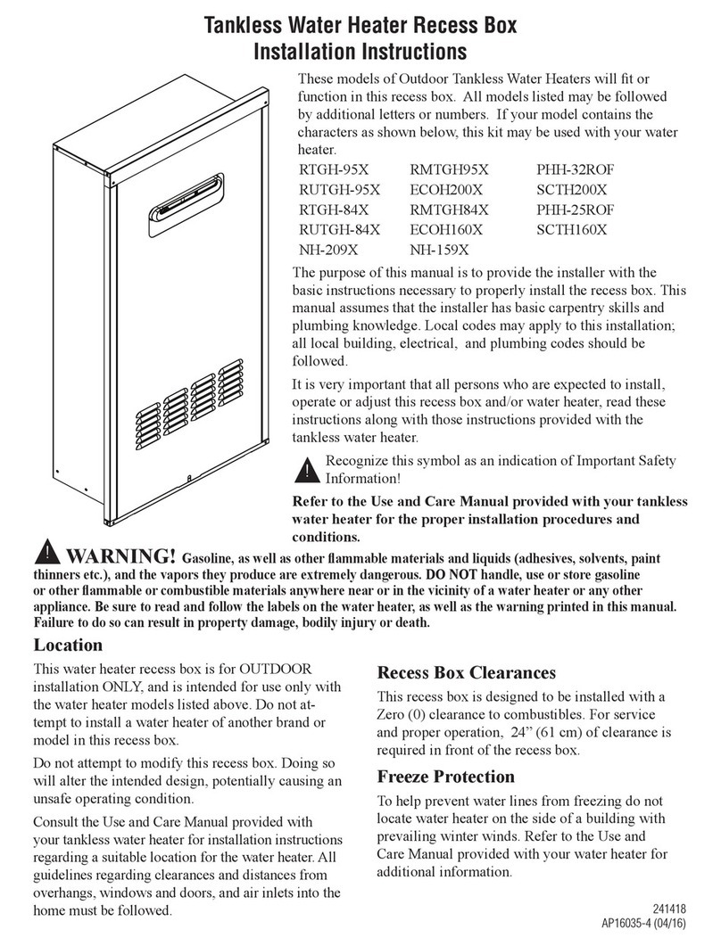
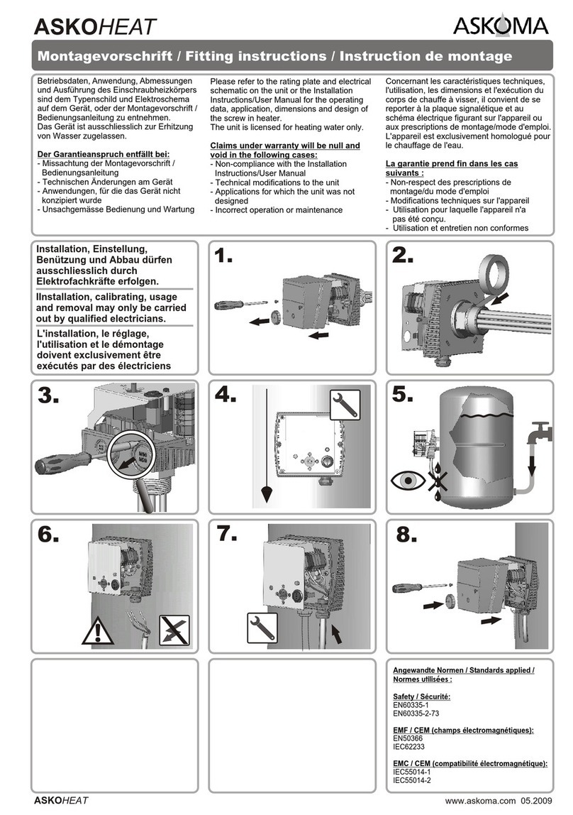
Laars Outdoor Cover User manual

800.900.9276 •Fax 800.559.1583 (Customer Service, Service Advisors)
20 Industrial Way, Rochester, NH 03867 •603.335.6300 •Fax 603.335.3355 (Applications Engineering)
1869 Sismet Road, Mississauga, Ontario, Canada L4W 1W8 •905.238.0100 •Fax 905.366.0130
www.Laars.com
Document 4306
Mascot ST Outdoor Cover Kit for Outdoor Installation
H2381300-
Page 1 of 4
This Outdoor Cover Kit is for NEW OUTDOOR INSTALLATIONS ONLY.
All precautions must be taken to prevent water in the heat exchanger and condensate inside and outside
of the boiler from freezing. Outdoor installations of the Mascot ST are intended for locations where
freezing temperatures rarely occur. Damage due to freezing water or freezing condensate is not covered
by the Mascot ST manufacturers warranty.
This Outdoor Cover Kit must be completed prior to the Mascot ST being installed.
Then the Mascot ST Installation Manual (Doc 1316) must be followed for the remainder of the
Installation. Doc 1316 is shipped with the new Mascot ST or can be downloaded at www.laars.com.
Follow the installation instructions or the Mascot ST warranty will be void.
The Mascot ST and this Mascot ST Outdoor Cover Kit must be installed by qualied and licensed
personnel. Installation must comply with
1. National Electrical Code
2. National Fuel Gas Code
3. In Canada, CSA C22.1 Canadian Electrical Code Part 1, and CGA No. B149 (latest version)
4. Local, state, provincial, and national codes, laws, regulations, and ordinances.
5. In the State of California: The water heater must be braced, anchored, or strapped to avoid moving
during an earthquake. Contact local utilities for code requirements in your area.
6. In the Commonwealth of Massachusetts:
a. Outdoor units may be used for summer use only.
b. The water heater may be used for water heating only and may not be used in a combination of
domestic and space heating.
When nished with the installation, be sure to keep the Installation and Operating Instructions nearby for
reference purposes.
These instructions include information specic to outdoor water heater installations. This information is meant to replace the venting section
included in the tankless water heater installation manual. The tankless water heater installation manual includes instructions that will be
necessary for the proper installation of all other functions, such as water and gas piping, wall mounting, control programming, etc. Failure to follow
these instructions could result in substantial property damage, severe personal injury, or death.
This installation shall be done by a qualied service agency in accordance with these instructions, all applicable codes, and requirements of the
authority having jurisdiction. Failure to follow these instructions could result in substantial property damage, severe personal injury, or death.
WARNING
WARNING
Carefully consider installation when determining water
heater location. Please read the entire manual and these kit
instructions before attempting installation.
Failure to properly take factors such as piping, condensate
removal, freezing, venting, and wiring into account before
installation could result in wasted time and money, and
possible property damage, personal injury, or death.
This OUTDOOR kit is meant for OUTDOOR installations ONLY.
DO NOT install the water heater and this kit indoors as it
will result in improper water heater operation and property
damage, and could result in serious personal injury or death.
WARNING
Incorrect ambient conditions can lead to damage to
the heating system and put safe operation at risk. Ensure
that the installation location adheres to the information
included in this manual. Failure to do so could result in
property damage, serious personal injury, or death. Failure of
heater or components due to incorrect operating conditions
IS NOT covered by product warranty.
WARNING
The water heater must be installed as described in these
instructions: Upright, with the supplied Outdoor Cover in the
vertical position. DO NOT attempt to install the water heater
in any other orientation. Failure to follow these instructions
will result in improper water heater operation and property
damage, and could result in serious personal injury or death.
Caution
Do not connect the water heater to any heating systems
potable applications.
Do not introduce toxic chemicals, such as antifreeze or
water heater treatments, into the water heater or any piping
meant for potable purposes.
NOT FOR INDOOR
INSTALLATIONS
800.900.9276 •Fax 800.559.1583 (Customer Service, Service Advisors)
20 Industrial Way, Rochester, NH 03867 •603.335.6300 •Fax 603.335.3355 (Applications Engineering)
1869 Sismet Road, Mississauga, Ontario, Canada L4W 1W8 •905.238.0100 •Fax 905.366.0130
www.Laars.com
Document 4306
Mascot ST Outdoor Cover Kit for Outdoor Installation
Page 2 of 4
5
Vent Termination Clearances
(CSA B149.1)
opening
meter / regulator assembly
Table 6 -Vent Termination Clearances
NOTE: For clearances not specified in ANSI Z223.1/NFPA 54 or CAN/CSA B149.1, use clearances in accordance with local installation codes
and the requirements of the gas supplier.
*Clearance to opposite wall is 24 in.
1
Avent shall not terminate directly above asidewalk or paved driveway that is located between two single family dwellings that serves both
dwellings.
2
Permitted only if veranda, porch, deck, or balcony is fully open on a minimum of two sides beneath floor.
LP-592 Rev.
1.20.16
Description US
(ANSI Z223.1/NFPA 54)
CANADA
AClearance above grade, veranda, porch, deck,
or balcony
12 in.
BClearance to window or door that may be
opened
4 ft. below or to side of
opening; 1 ft. above
3 ft.
CClearance to permanently closed window *
D
Vertical clearance to ventilated soffit located above
the terminal within ahorizontal distance of 2 feet
from the center line of the terminal
*
EClearance to unventilated soffit *
FClearance to outside corner *
GClearance to inside corner *
HClearance to each side of center line
extended above meter / regulator assembly
*3 ft. with a height 15 ft. above
IClearance to service regulator vent outlet *3 ft.
J
Clearance to non-mechanical air supply inlet to
building or the combustion air inlet to any other
appliance
4 ft. below or to side of
opening; 1 ft. above
opening
3 ft.
K
Clearance to a mechanical air supply inlet 3 ft. above if within 10 ft.
horizontally
6 ft.
LClearance above paved sidewalk or driveway *7 ft.
1
MClearance under veranda, porch, deck, or
balcony
*
1 ft.
2
• Outdoor Installation Area Operating Conditions Ensure ambient
temperatures are higher than 32°F / 0°C and lower than 104°F / 40°C.
• Prevent the air from becoming contaminated by the products,
places, and conditions listed in the water heater installation manual.
• Avoid continuously high levels of humidity.
Check for nearby connections to System water piping, Venting
connections, Gas supply piping, Electrical power, and the
Condensate Drain.
Check area around heater. Remove any combustible
materials, gasoline, and other ammable liquids.
Clean and ush system when re-installing a heater.
If the heater is to replace an existing heater, check for and
correct any existing system problems, such as:
• System leaks.
• Location that could cause the system and heater to freeze and leak.
• Incorrectly sized expansion tank.

800.900.9276 •Fax 800.559.1583 (Customer Service, Service Advisors)
20 Industrial Way, Rochester, NH 03867 •603.335.6300 •Fax 603.335.3355 (Applications Engineering)
1869 Sismet Road, Mississauga, Ontario, Canada L4W 1W8 •905.238.0100 •Fax 905.366.0130
www.Laars.com
Document 4306
Mascot ST Outdoor Cover Kit for Outdoor Installation
Page 3 of 4
3. Using the phillips screw drivier, remove the original vent pipe collar.
Save the screws for re-use in Step 4.
4. Place the Exhaust Adapter into the exhaust vent and fasten it into
place using the original screws.
5. Install the Exhaust Pipe into the Exhaust Vent Adapter. Ensure the
pipe is positioned as shown.
6. Take one of the Vent Screens from the Mascot ST installation kit
and insert it to the intake vent collar as shown. Tighten it down
using the clamp on the vent collar.
Qty
Included Kit Component
Descriptions
#
1 Outdoor Cover 1
2Self Tapping Screws 2
1 Exhaust Pipe 3
1 Exhaust Screen 4
1Exhaust Adapter 5
1 Replacement Front Cover 6
1 Outdoor Kit Instructions 7
LP-592 Rev. 1.20.16
8
Replacement Parts
Figure 11 - Replacement Parts
Number Description Part Number Number Description Part Number
17850P-257 57850P-088
27855P-258 67855P-255
37855P-389 77855P-389
47850P-259
Table 7 - Replacement Parts
Outdoor Enclosure Exhaust Screen
Exhaust Pipe Front Cover
M4 X 10 TH + Self Tapping Screws M4 X 10 TH + Self Tapping Screws
Exhaust Adapter
1
3
2
4
5
6
7
Screw Gun w/ 8mm Socket Drive.
Phillips Head Screw Driver
Tools Needed for Kit Installation
3
4
1 2
6
5
Installing the Outdoor Cover Kit
1. Remove the front cover from the unit. Keep the 4 original screws
for re-use. They will be used later to fasten the Replacement
Front Cover to the unit. Discard the original front cover as this kit
includes a replacement front cover desgined for outdoor use.
2. Carefully stand the unit up in the box, using the styrofoam in the box
to protect the components on the bottom of the unit. Or set the unit
onto one of it's sides on a steady workbench.

800.900.9276 •Fax 800.559.1583 (Customer Service, Service Advisors)
20 Industrial Way, Rochester, NH 03867 •603.335.6300 •Fax 603.335.3355 (Applications Engineering)
1869 Sismet Road, Mississauga, Ontario, Canada L4W 1W8 •905.238.0100 •Fax 905.366.0130
www.Laars.com
Document 4306
Mascot ST Outdoor Cover Kit for Outdoor Installation
Customer Service and Product Support: 800.900.9276 • Fax 800.559.1583
Headquarters: 20 Industrial Way, Rochester, NH, USA 03867 • 603.335.6300 • Fax 603.335.3355
1869 Sismet Road, Mississauga, Ontario, Canada L4W 1W8 • 905.238.0100 • Fax 905.366.0130
www.Laars.com Litho in U.S.A. © Laars Heating Systems 1612 Document 4306
H2381300-
Page 4 of 4
WARNING
The Outdoor Cover for the Masoct ST is not designed to carry heavy weight. Do not stack anything on the water heater.
Doing so could result in substantial property damage, personal injury, or death.
9. FROM THE BACK OF THE UNIT. With the Exhaust Screen in place and the
Outdoor Cover sitting at and level on the top, use the two provided hex-head self-tapping
screws and a power drill and fasten the Outdoor Cover to the unit.
Of the 4 holes that are on the back of the Outdoor Cover, use the 2 outermost holes as shown.
8
9
10 11 X 4
x2
8. Align the Exhaust Screen into the Exhaust Pipe and press it into place.
10. Lift the Replacement Front Cover onto the unit. It will t under the Outdoor Cover
and then over the same hanger as the original front cover and the holes for the
screws will align.
NOTE: At this point, refer to the Mascot ST Installation &
Operating Instructions (Doc 1316) to install the unit to it's
OUTDOOR location. Once the installation of the Mascot ST is
complete and is running properly, then proceed to Step 10 of
this instruction.
11. Fasten the new
outdoor front cover
into place
using the four (4)
original phillips
head screws.
7
Detail
7. Fit the Outdoor Cover onto the top of the unit. The small brackets on the inside of the
cover will t down onto the top of the unit behind the lip that the front cover hangs over.
Table of contents