LaGard 8130 User manual

To ensure problem free installation and application, please read these instructions thoroughly before installing the 8130 Entry Device
and Lock.
8130 ENTRY DEVICE PARTS
• 8130 Entry Device w/Cable Assembly
• Metric Hardware Kit
•2 Position Shunt (Jumper)
•M4-0.7 5.5 mm Diam x 5.5 mm Shoulder Screws (2) (for Standard Mounting Method)
•M4-0.7 x Phillips Head Screws (2) (for Alternate Mounting Method)
• English Hardware Kit
•#8-32 .218 Diam x .2 Shoulder Screws (2) (for Standard Mounting Method)
LOCK OPTIONS
Dual-Handed Swing Bolt, Dead Bolt, Spring Bolt or Redundant Mechanical Lock
with one of the following lock codes:
ComboGard (33E V2.13)
ComboGard Pro (39E V1.01)
AuditGard (66E LGA V1.20)
TimeGard (TL11 V1.30 and V2.22)
Note: Hardware Kit included with lock.
OPTIONAL ACCESSORIES
• Knob Assembly - P/N 2666 (recommended for use with Dead bolt or Spring bolt locks).
• VisionGard Dial Assembly - P/N 2085 (for use with Redundant Mechanical lock). An entire range of LA GARD dials is available for
alternate dial options.
• Battery or Battery/Alarm Box (recommended if using with Time Delay/TimeLock. Alarm Box is required for use of certain features).
•Small box: P/N 2788 or 2789
•Large box: P/N 4001 or 4002
INSTALLATION INSTRUCTIONS
(P/N)738.098 Rev A • 04/09 © copyright 2009 Kaba Mas LLC
page 1 of 5
8130
8130
Electronic Entry Device with Lock
The installation instructions are the basis for Security Agency Approvals. The lock installation must be done in accordance to these
instructions in order to maintain the labeled approval level.
DESIGN PARAMETERS FOR DEAD BOLT LOCKS
1. Bolt dimensions (nominal): .312 inches x 1.000 inches/8 x 25.4mm
2. Bolt movement (nominal): .465 inches/11.8mm
3. Bolt extension: .465 inches/11.8mm
4. Maximum load movable by the bolt: 5 lbs. (22N)
Note: LA GARD dead bolt locks may not open if more than 5 lbs. (22N) of force is applied to the end or side of the bolt.
5. Maximum load against bolt when thrown (all directions): 224.8 lbs. (1kN)
6. The lock can be fitted to safes or vault doors of any material.
Note: As is the case with all mechanical and electronic locking devices, the container and boltworks must be designed to protect
the lock.
2788 Small Battery Box
2789 Small Alarm/Battery Box
4001 Large Battery Box
4002 Large Alarm/Battery Box
2666 Knob Assembly
(For use with Dead Bolt or Spring Bolt Locks)
2085 VisionGard Assembly
(For use with Redundant
Mechanical Locks)
Dual-Handed
Swing Bolt Lock
Dead bolt Lock or
Spring Bolt Lock Redundant
Mechanical Lock

(P/N)738.098 Rev A • 04/09 © copyright 2009 Kaba Mas LLC
page 2 of 5
DESIGN PARAMETERS FOR SWING BOLT LOCKS
1. Bolt dimensions (nominal): .309 inches x .900 inches/7.8 x 22.8mm
2. Bolt movement (nominal): .465 inches/11.8mm
3. Bolt extension: .465 inches/11.8mm
4. Maximum load movable by the bolt: None
Note: LA GARD swing bolt locks will not open if force is applied to the end or side of the bolt.
5. Maximum load against bolt when thrown (all directions): 1kN (224.8 lbs.)
6. The lock can be fitted to safes or vault doors of any material.
Note: As is the case with all mechanical and electronic locking devices, the container and boltworks must be designed to protect
the lock.
SAFEGUARDS FOR MOUNTING
1. Once an electronic lock has been mounted, no more welding can be done on the safe.
2. Keep metal dust, filings, etc. away from the lock.
3. Never remove lock cover on a Dead Bolt, Spring Bolt or Swing Bolt lock as this voids warranty policy.
4. Never oil, grease, lubricate or paint the lock.
5. Keep cables away from sharp edges and moving parts.
6. Never carry keypads or locks by the cable.
7. Use 9-Volt ALKALINE batteries only. The use of a high quality, name brand battery (Energizer® or Duracell®) is recommended.
BASIC TOOLS AND MATERIALS REQUIRED:
• Medium Phillips head screwdriver (#2) (recommend magnetized tip)
• Torque screwdriver
• Small flat file or deburring stone
• Tape measure or ruler
• ESD wrist band
For dead bolt, spring bolt, or redundant mechanical installation:
• Fine pitch hacksaw (32 teeth/inch)
• Small vise grip (Recommended)
WARNING: LA GARD locks are protected from 25,000 V Electrostatic Discharge (ESD) damage when correctly installed. Follow
these precautions to avoid ESD damage when installing the lock:
• Handle the keypad assembly by the outer edge only.
• Use an ESD wrist band grounded to the lock or container during installation.
PREPARATION FOR NEW INSTALLATION: (IF REQUIRED)
1. Use the template provided to establish the exact locations (relative to the spindle hole) of the mounting holes for the Entry Device
and the lock assembly. Be sure to consider the cable length from the entry device to the lock.
2. The spindle hole diameter can be a minimum of .406"(10.3mm) to a maximum of .438"(11.1mm). The .406"(10.3mm) diameter is
recommended. Spindle hole must be deburred.
3. The Entry Device mounting screws require drilled and tapped holes to 3/8"(9.5mm) depth if possible (minimum 1/4"or
6.4mm depth required.) Drill either the two horizontal mounting holes or the two vertical holes.
4. When mounting the lock unit (i.e., integrating it in a boltwork), make sure that the lock bolt has clearance to freely move to its end
positions and that the shifting force works only in the axial direction (direction of movement). Lateral forces should not be exerted on
the lock.
5. If other parts of the boltwork are to be connected to the lock unit (e.g., for activating a blocking device), corresponding adapters can
be fixed with screws (#10-32 or M4) to the front of the lock bolt (tightening torque for 15mm screwing depth: 200Ncm maximum).

(P/N)738.098 Rev A • 04/09 © copyright 2009 Kaba Mas LLC
page 3 of 5
ENTRY DEVICE MOUNTING
STANDARD METHOD
The 8130 Entry Device comes with a backplate for ease of mounting. (Figure 1)
1. Locate, drill and tap holes to mount the Entry Device to the outside of the safe door using the installation template provided.
2. Install the two #8-32 shoulder screws (US) or the two M4-0.7 shoulder screws (Metric) on the front of the safe door to mount the
Entry Device to the door. (Figure 2)
3. Feed the Entry Device cable through the spindle cable hole from the front of the safe door. (Figure 3)
4. Position the slotted holes on the backplate of the Entry Device over the mounting screws and then slide the Entry Device down onto
the mounting screws.
5. Remove the adhesive strip from the back of the keypad and carefully align before adhering to the housing.
ALTERNATE METHOD (TAMPER EVIDENT FOR VdS APPROVAL)
The 8130 Entry Device comes with the mylar portion of the keypad unattached. (Figure 4)
1. Locate, drill and tap holes to mount the Entry Device to the outside of the safe door using the
installation template provided.
2. Feed the Entry Device cable through the spindle/cable hole from the front of the safe door.
3. Install the two M4-0.7 Phillips screws through the front of the housing to mount the Entry Device to
the door. (Figure 4)
Warning: Before completing the next step, you should ensure that the jumper switches for time delay/
open window are set as desired.
4. Remove the adhesive strip from the back of the keypad and carefully align before adhering to the
housing.
LOCK CONNECTION AND MOUNTING
SWING BOLT
1. Locate, drill and tap holes to mount the Lock Assembly to the inside of the safe door using the
installation template provided.
2. Ensure that the Entry Device cable is running through the channel at the back of the lock. Mount the lock with
the three US 1/4"-20 (Metric M6X1) screws.
Note: All four mounting orientations are possible. The recommended torque for mounting screws on the Swing bolt lock is 30
in./lbs. for the US 1/4"-20 screws (3.4 N•m for Metric M6X1). (Figure 5)
3. Secure any cables with wire tie, making sure to keep out of the way of all moving parts. (Figure 6)
4. The blocking part “A” of boltwork should exert pressure on the entire width of the lock bolt. In the locked position the boltwork
MUST NOT place pressure on the lock bolt.
Note: In case of boltwork construction where two blocking parts are moving opposite one another, the one facing the round side
of the lock bolt “B” should be cut off to avoid jamming of lock bolt. (Figure 7)
Figure 1 Figure 2 Figure 3
Figure 5 Figure 6 Figure 7
Figure 4

(P/N)738.098 Rev A • 04/09 © copyright 2009 Kaba Mas LLC
page 4 of 5
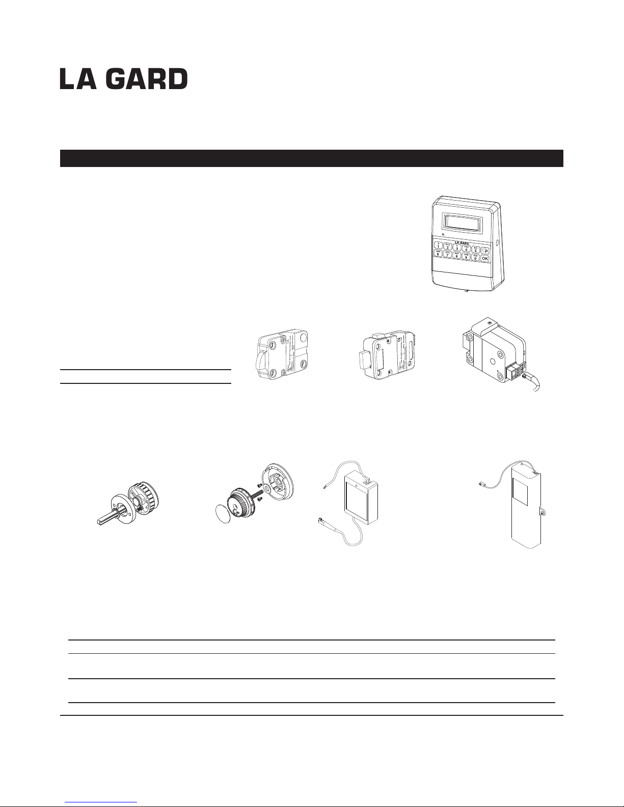
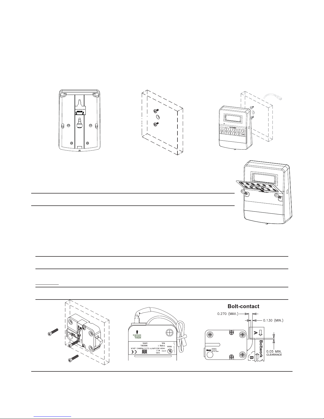
5. Connect the cable coming from the Entry Device directly into the connector port marked ENT on the lock. (Figure 6)
DEAD BOLT OR SPRING BOLT LOCKS
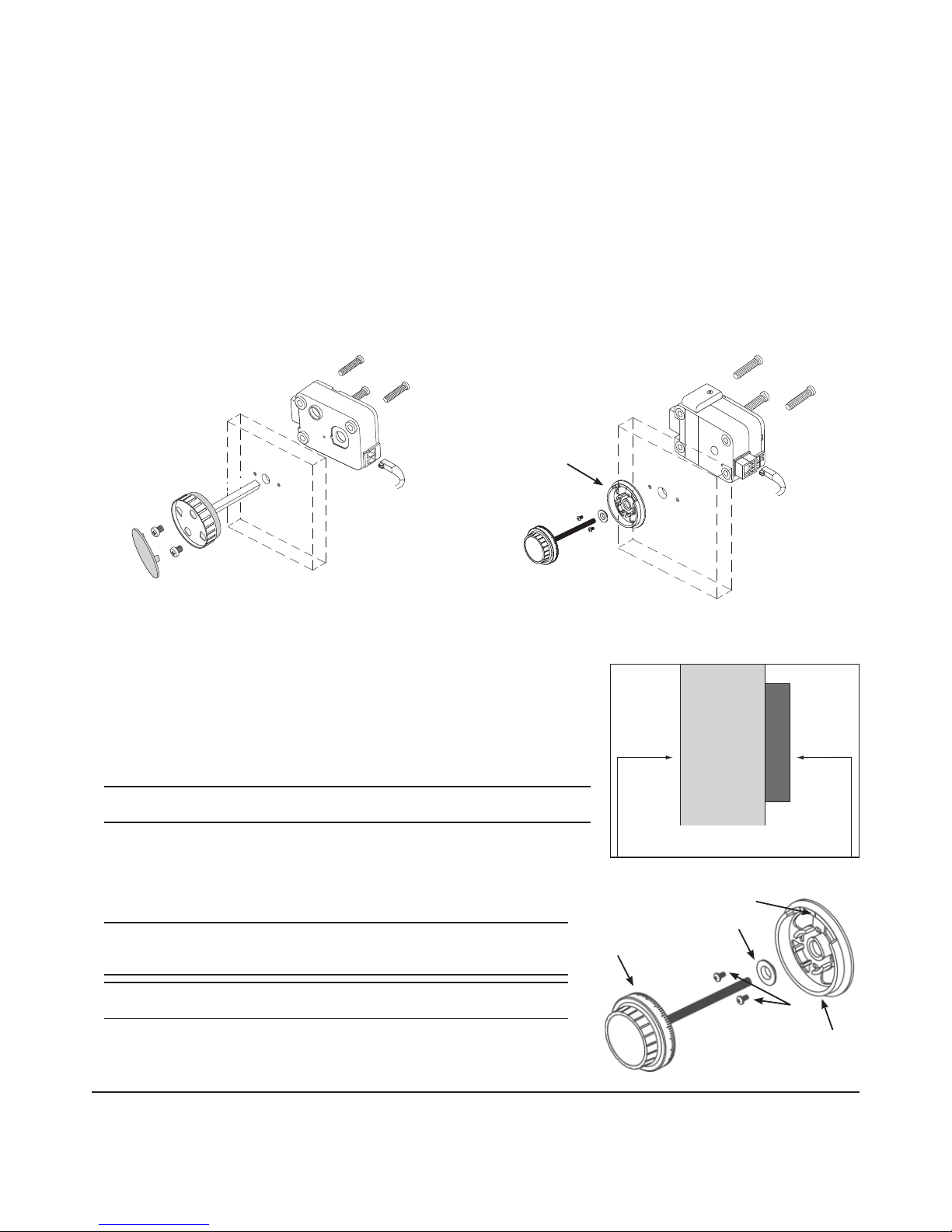
In order to use either the Dead bolt or Spring bolt locks, a method of retracting the bolt will be required. Knob Assembly - P/N 2666 -
(Figure 8) is recommended.
The drilling holes necessary to mount the lock correspond with the standard dimensions for mechanical locks. The spindle hole must
be well deburred and no sharp edges may remain. The holes required to mount the knob need to be drilled 1.25"apart and must be
centered over the spindle hole.
1. Locate, drill and tap holes to mount the Lock Assembly to the inside of the safe door using the installation template provided.
2. To install the Knob Assembly, remove the insert from the front of the knob.
3. Cut the spindle to a length of .820"(20.8mm) plus the mounting thickness.
4. Install the knob assembly using the two 8-32 X 5/16 phillips pan screws. (Figure 8)
5. Install the lock (always with the bolt extended) onto the spindle, placing it flush to the mounting surface.
6. Attach the lock using the three US 1/4"-20 (Metric M6X1) screws found in the hardware pack.
7. Connect the cable coming from the Entry Device directly into the connector port marked ENT on the lock. (Figure 8)
REDUNDANT MECHANICAL LOCKS
In order to use a Redundant Mechanical lock, a method of retracting the bolt is required.
Use of the VISIONGARD Dial (P/N 2085) is recommended (Figure 9). An entire range of
LA GARD dials is available for alternate dial options.
1. Locate, drill and tap holes to mount the Lock Assembly to the inside of the safe door
using the installation template provided.
2. Locate and drill the two holes for the dial ring to be mounted.
3. Attach the lock assembly to the door using the three US 1/4”-20 (Metric M6X1)
mounting screws provided. Tighten the mounting screws to a torque setting of 30
in./lbs. (3.4 N•m).
Note: Ensure the lock assembly spindle hole is properly aligned with the spindle
through hole in the safe door.
4. Measure total mounting thickness (door thickness + mounting plate). (Figure 10)
5. Cut the spindle to a length of 1.125” (28.6mm) plus the total mounting thickness.
6. Mount the dial ring centered on the through hole, and attach to the safe door using the
two mounting screws supplied with the dial assembly. The opening index reference
mark must be in the twelve o’clock position. (Figure 11)
7. Place the dial bearing onto the dial ring.
WARNING: The lock bolt MUST remain in the retracted position throughout the
installation procedure. To ensure this keep one finger over the bolt while installing
the dial spindle into the lock cam.
WARNING: Ensure that you are properly grounded to protect the system card from
Electrostatic Discharge (ESD) damage before proceeding with the next steps.
8. Remove the two cover screws from the back cover of the lock assembly, and
remove the lock back cover. (Figure 12)
9. Carefully unplug the solenoid connector from the system card. (If applicable,
unplug the bolt switch connector from the system card.) (Figure 12)
Figure 8 Figure 9
Dial ring
Figure 10
DOOR
MOUNTING PLATE
Total Mounting Thickness = door thickness
+ mounting plate
Dial
Dial
Ring
Mounting
Screws
Dial Bearing
Opening
Index
Figure 11

10. Remove the mounting screw from the system card, and
gently lift the system card out of the case. (Figure 12)
11. Insert the spindle through the spindle hole in the front of
the door.
12. With the bolt retracted, carefully thread (clockwise) the
spindle into the drive cam of the lock assembly
until tight.
13. Next, rotate (counterclockwise) at least 1/2 turn until the
groove in the spindle is aligned with the correct spline
position. The correct spline position for the installation
orientation showing in Figure 12 is RH (for a “Right
Hand” door.) Refer to the following Spline Key
Position Chart for all mounting positions.
Spline Key Position Chart
The lock may be mounted in four positions - align the spindle groove with the
corresponding cam position. The positions are
• RH (right hand)
Lock bolt points right as you view the lock from the back side of the door.
• LH (left hand)
Lock bolt points left as you view the lock from the back side of the door.
• VU (vertical up)
Lock bolt points upward.
• VD (vertical down)
Lock bolt points downward.
14. Insert the spline key fully into the cam from the back of the lock assembly by tapping it into place.
Important Note: Ensure the spline key is seated against the spindle.
15. Reinstall the system card.
16. Reconnect the solenoid (and bolt switch if applicable.)
17. Reinstall the back cover.
18. Connect the cable coming from the Entry Device directly into the connector port marked ENT on
the lock.
Note: Ensure the cable is secure and away from any moving parts.
BATTERY INSTALLATION
Caution: Keep the container door open during battery installation.
1. Remove the battery compartment cover at the bottom of the entry device.
2. Connect a new 9-Volt Alkaline battery to the battery connector. Use of a high quality,
name brand battery (Energizer® or Duracell®) is recommended.
Note: Once the battery is connected, the system will run a self check of the display
and buzzer.
3. Place the battery back in the battery compartment and put the cover back in place.
(P/N)738.098 Rev A • 04/09 © copyright 2009 Kaba Mas LLC
page 5 of 5
Cam
Figure 13
Bolt positions as viewed from the back of
the lock.
Figure 14
Mounting
Screws
Solenoid
Connector
Card and
Card Screw
Cam
Bolt
Switch
Cover
Screws
Figure 12
749 W. Short Street, Lexington, KY 40508 USA
Phone: (859) 253-4744 FAX: (859) 255-2655
Technical Support: (800) 950-4744
www.kaba-mas.com
Other manuals for 8130
1
Table of contents
Other LaGard Door Lock manuals
Popular Door Lock manuals by other brands

RemoteLock
RemoteLock OpenEdge BG Hardware installation

Assa Abloy
Assa Abloy effeff 843 Installation and mounting instructions

Schlage
Schlage BE365 installation instructions

CAMDEN
CAMDEN CX-EPD1289L installation instructions

ShineACS
ShineACS SL-C10 Series user manual

FingerTec
FingerTec ML-10B quick start guide