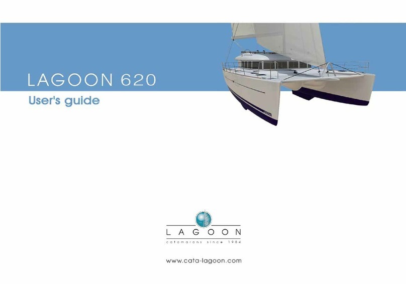
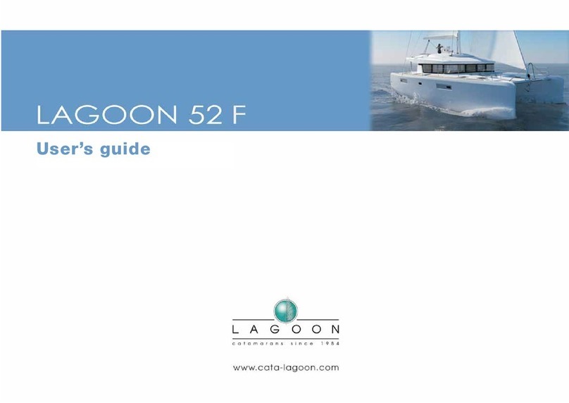
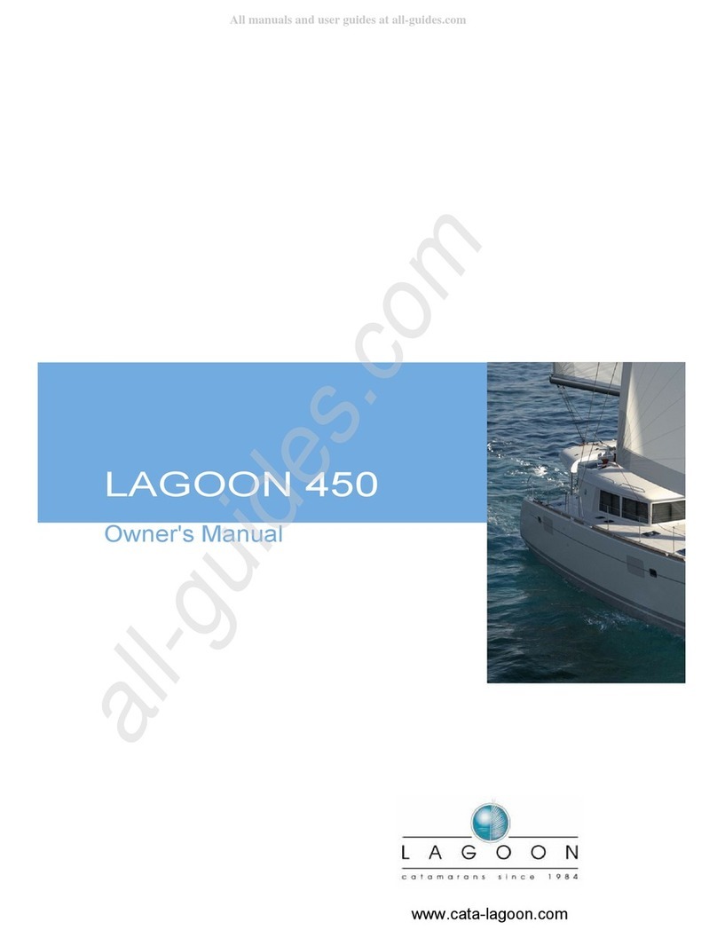
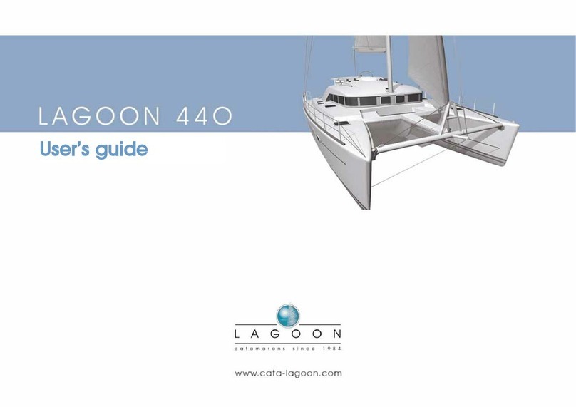
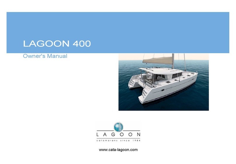
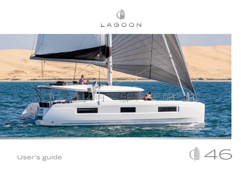
Lagoon 420 User manual

LAGOON 420 – ANG– 06/09/2007 1 / 30
CONSTRUCTION NAVALE BORDEAUX
OWNER’S MANUAL
LAGOON 420
FR-BEY _ _ _ _ _ _ _ _ _
REF:
CONTENTS:
1INTRODUCTION ....................................................................................................................................... 2
2CARACTERISTICS ................................................................................................................................... 4
2.1 THE BOAT’S IDENTITY SHEET..................................................................................................................... 4
2.2 DIMENSIONS .............................................................................................................................................. 4
2.3 LOAD......................................................................................................................................................... 5
2.4 SAILS AND RIGGING ................................................................................................................................... 7
3SAFETY ..................................................................................................................................................... 10
3.1 FIRE......................................................................................................................................................... 10
3.2 VISIBILITY ............................................................................................................................................... 12
3.3 STABILITY,RISK OF FLOODING ................................................................................................................ 12
3.4 PREVENTION OF FALLING OVERBOARD .................................................................................................... 13
3.5 LIFE RAFT (NOT SUPPLIED) ...................................................................................................................... 13
4EQUIPMENT ............................................................................................................................................ 14
4.1 ENGINE.................................................................................................................................................... 14
4.2 STEERING SYSTEM ................................................................................................................................... 16
4.3 ELECTRICAL SYSTEM ............................................................................................................................... 17
4.4 GAS SYSTEM ............................................................................................................................................ 21
4.5 FRESHWATER AND BLACK WATER TANKS................................................................................................ 22
4.6 PUMPS,SEACOCKS AND SKIN FITTINGS ................................................................................................... 24
5ANCHORING, MOORING AND TOWING.......................................................................................... 26
6HAULING OUT AND TRANSPORTATION ........................................................................................ 27
7SNSM.......................................................................................................................................................... 29
8CHARTER FOR THE SEA AND INLAND WATERWAYS ............................................................... 30

LAGOON 420 – ANG– 06/09/2007 2 / 30
1 INTRODUCTION
Dear Madam, dear Sir,
You have just taken delivery of your new LAGOON, and we would first of all like to thank you for
your confidence in choosing one of our products.
A LAGOON is built to last: each boat is the subject of attentive care down to the slightest details, from
her design until she leaves the factory and is launched, so that she will provide you with the many years of joy
that you expect from her.
This manual has been drawn up to help you use your boat in safety and with pleasure. It contains details
about the boat, the equipment supplied or fitted, her systems and information on their use. Some of this
equipment may be optional. Read it carefully and familiarise yourself with the boat before using her.
Even when your boat has been accordingly categorised, the conditions of sea and wind corresponding to
design categories A, B and C vary from strong storm to severe conditions, open to risks of abnormal waves and
gusts, and are consequently dangerous conditions, where only an experienced crew, physically fit and well
trained, manoeuvring a well maintained boat may sail satisfactorily.
Make sure that the forecast wind and sea conditions correspond with the design category of your boat, and that
you and your crew are capable of manoeuvring the boat in those conditions.
This owner’s manual is not intended to be a course on sailing safety or seamanship. If this boat is your
first boat or if you are changing to a type of boat you are not familiar with, for your comfort and safety, make
sure you get experience on manoeuvring and using her before taking command. Your dealer, national sailing
federation or powerboating federation or your yacht club will be delighted to direct you to competent sailing
schools or instructors in the region.
This owner’s manual is not a detailed maintenance or repair guide. In case of difficulty contact the
manufacturer of the boat or one of its representatives.
Always use the services of an experienced professional for maintenance or the fitting of accessories.
The modifications that might affect the safety characteristics of the boat should be evaluated, carried out and
documented by competent people. The manufacturer of the boat cannot be held responsible for modifications
that it has not approved.
NOTE : Any change in the weight distribution on board (for example the addition of a raised fishing platform,
a radar, a furling mast, a change of engine, etc.) can effect the stability, the trim and the performance of your
boat.
PLEASE KEEP THIS MANUAL IN A SAFE PLACE AND HAND IT TO THE NEW OWNER IF YOU
SHOULD SELL THE BOAT.

LAGOON 420 – ANG– 06/09/2007 3 / 30
The users of this boat are advised that:
-The entire crew should receive appropriate training
-In some countries, a driving licence or an authorisation is needed, or there are specific regulations in force.
-Always maintain your boat correctly and take into account deterioration resulting from time and significant
or inappropriate wear of the boat.
-Any boat – however strong – can be severely damaged if poorly used. This is not compatible with safe
boating. Always adjust the speed and direction of the boat to the state of the sea.
-If your boat is equipped with a life raft, carefully read its instruction manual. The crew should be familiar
with the use of all safety equipment (harnesses, flares, life raft, etc.) and emergency safety manœuvres
(recovering a person overboard, towing, etc.), sailing schools and clubs regularly organise training sessions.
-Do not sail at maximum speed in zones of heavy traffic, or in case of reduced visibility, strong winds or big
waves. Reduce the speed and wake of the boat, out of courtesy and for safety’s sake for yourself and for
others. Respect zones of speed and wake limits.
-Observe rules of priority such as defined by the rules of the road and imposed by the COLREGS
(regulations for the prevention of collisions at sea).
-Make sure you always have sufficient distance to stop or manœuvre if necessary in order to avoid a
collision.
Explanation of the typography used:
-DANGER
-WARNING
-ATTENTION

LAGOON 420 – ANG– 06/09/2007 4 / 30
2 CARACTERISTICS
2.1 The boat’s identity sheet
•NAME OF BUILDER ……………………... Construction Navale Bordeaux
•DESIGN CATEGORY…………………. A
•MAXIMUM RECOMMENDED POWER…... 30 KW
•N° OF NOTIFIED BODY CE 0607
CATEGORY HEIGHT OF
WAVES (m)
WIND FORCE
(BEAUFORT)
A > 4 >8
B < 4 ≤8
C < 2 ≤6
D < 0.3 ≤4
MAXIMUM RECOMMENDED NUMBER OF PERSONS BY DESIGN CATEGORY:
CATEGORY MAXIMUM
NUMBER OF
PERSONS
A 11
B 13
C 18
D 20
2.2 Dimensions
LENGTH OF HULL 12.61 m*
BEAM OF HULL 7.53 m*
LENGTH OVERALL 12.64 m
BEAM OVERALL 7.53 m
DRAUGHT 1.30 m
MAX AIR DRAUGHT 2.00 m
* according to ISO 8666 standard

LAGOON 420 – ANG– 06/09/2007 5 / 30
2.3 Load
DESIGN CATEGORIES A B C D
Boat lightship: 11883 11883 11883 11883
Safety equipment: 200 200 200 200
Sails: 85 85 85 85
Lightship displacement:12168 12168 12168 12168
Life raft: 179 179 179 179
Crew: 825 975 1,350 1,500
Water: 350 350 350 350
Fuel: 480 480 480 480
Personal effects 220 240 290 310
Optional equipment
Spinnaker rigging + spinnaker 40 40 40 40
Gennaker rigging + gennaker 40 40 40 40
Electric genoa sheet winch x2 56 56 56 56
Lazy bag + Lazy jack 8 8 8 8
Bimini windshield 5 5 5 5
Canopy panel with ports 12 12 12 12
Extra bathing ladder 7 7 7 7
Outboard motor mount 2 2 2 2
Davits 45 45 45 45
Electric davit winch 15 15 15 15
Teal aft cockpit 12 12 12 12
Pulpit (wooden seat) 3 3 3 3
Sunbed 7 7 7 7
Cockpit cushion 10 10 10 10
Deck wash 20 20 20 20
2nd cockpit shower 2 2 2 2
Shore freshwater supply filler 6 6 6 6
Seawater footpump 4 4 4 4
Freshwater footpump 2 2 2 2
Microwave grill 20 20 20 20
Dishwasher 25 25 25 25
Freezer 30 30 30 30
Watermaker 60 60 60 60
Icemaker 30 30 30 30
Cockpit fridge 14 14 14 14
Washing machine 52 52 52 52
Saloon + cabin ventilators 4 4 4 4
46000 BTU air-conditioning unit 142 142 142 142
Slatted bases in 4-cabin version 24 24 24 24
Door curtain 3 3 3 3
Rigid WC holding tank 90 90 90 90

LAGOON 420 – ANG– 06/09/2007 6 / 30
Electric WC x 4 16 16 16 16
Service battery x2 85 85 85 85
40A / 80A battery charger 6 6 6 6
12 / 220 2500W inverter 14 14 14 14
Generator 9.5KVA 220V 350 350 350 350
Antifouling 40 40 40 40
Saloon + cabin TV – aerial 23 23 23 23
Radio/CD player + 2 speakers 3 3 3 3
Waterproof cockpit speaker (X4) 3 3 3 3
VHF 1 1 1 1
GPS 2 2 2 2
Electronic: Speedo/Depth/Plotter 11 11 11 11
Automatic pilot 10 10 10 10
Radar 3 3 3 3
Warps and fenders 30 30 30 30
Mosquito nets 1 1 1 1
Tender + engines 200 200 200 200
Diving equipment 60 60 60 60
Other 10 10 10 10
Margin for extra equipment 765 595 170 0
MAXIMUM LADEN
DISPLACEMENT(kg)
16645 16645 16645 16645
MAXIMUM LOAD (kg) 4477 4477 4477 4477
MAXIMUM LOAD = maximum laden displacement – lightship displacement
Any excess may lead to a flooding or loss of stability
WEIGHT FOR TRANSPORTATION: take into consideration the lightship displacement of the boat, the
options, equipment and consumables left aboard during the transportation.
The maximum recommended load shown on the boat builder’s plate complies with EU directive 2003/44
EC, but does not include the full weight of the various fixed tanks installed on the boat (fuel, water, grey
water and black water tanks).

LAGOON 420 – ANG– 06/09/2007 7 / 30
2.4 Sails and rigging
2.4.1 Characteristics of the sail plan:
SAIL CLASSIC SAIL
AREA
DIMENSIONS
MAINSAIL 60 m² I 15.33 m
GENOA (MAX) 34 m² J 3.99 m
GENNAKER 70 m² P 15.67 m
E 6.14 m
2.4.2 Maintenance of the rigging:
-Check the standing and running rigging regularly, and at least once per year.
For wire cables:
-Change them as soon as the first frays appear
-Check for corrosion, especially at the terminals with rigging screws.
-Check the good condition of swages and rigging screws.
For synthetic cables (Kevlar, Twaron, etc.) used for running backstays, halyards, sheets, docklines, etc.:
-Change as soon as signs of fray or wear appear.
-Regularly check the other elements of the rigging; sheets, docklines, etc. ; and replace if worn.
P
LP
PI
J
E

LAGOON 420 – ANG– 06/09/2007 8 / 30
2.4.3 Running rigging plan
Traditional mast
REF DESCRIPTION
1 Reef 1
2 Reef 2
3 Reef 3
4 Mainsail sheet
5 Mainsail halyard
6 Boom uphaul
7 Spinnaker halyard
8 Genoa halyard
9 Genoa furling line
10 Mainsail traveller track purchase
system - port
11 Mainsail traveller track purchase
system – starboard
12 Port genoa sheet
13 Starboard genoa sheet

LAGOON 420 – ANG– 06/09/2007 9 / 30
REDUCING SAIL
ATTENTION: Sail settings other than these recommendations may cause the mast to fail.
More specifically: the genoa should never be flown full with 2 reefs in the mainsail.
Max. actual wind speed
Force Knots Sailplan
1-4 20
Mainsail 100%
Genoa 100%
5 25
Mainsail (reef 1)
Genoa 100%
6 30
Mainsail (reef 1)
Genoa 70%
7 35
Mainsail (reef 2)
Genoa 70%
8 40
Mainsail (reef 2)
Genoa 30%
9 45
Mainsail (reef 3)
Genoa 30%

LAGOON 420 – ANG– 06/09/2007 10 / 30
3 SAFETY
3.1 Fire
3.1.1 Risks
The main risks are associated with the engine (§ 4.1), the electrical system (§ 4.3) and the gas system (§ 4.4).
Please consult the relevant chapters.
3.1.2 Fire fighting equipment
3.1.2.1 Portable extinguishers
The boat is delivered without extinguishers, the application of the national regulations of the country of registration of
your boat are your responsibility. The boat must be equipped, when in service, with portable extinguishers
We recommend the installation of at least one extinguisher less than 5 metres from each berth, less than 2 metres from
the engine compartment extinguishing aperture, less than 2 metres from any naked flame appliance and less than 1
metre from the helm station. We recommend a total portable extinguishing capacity of 8A/68B, each appliance having
less than a capacity of 5A/34B. CO2extinguishers should be dedicated to galley or electrical fires.
The recommended places for the extinguishers are identified with the symbol
On boats fitted with an inboard engine, there is a discharge aperture for the engine compartment whose location is
identified on the following diagram by the symbol:
3.1.3 Escape routes
The recommended escape routes are indicated on the opposite diagram by the arrow:
E
O

LAGOON 420 – ANG– 06/09/2007 11 / 30
3.1.4 Preventive advice
3.1.4.1 General
-Do not freely hang curtains or any other fabrics close to or above cooking appliances or other naked
flame appliances.
-Keep the bilges clean and regularly check for the absence of vapours and fuel or gas leaks.
-Do not stow combustible materials in the engine compartment.
-Do not leave the boat unattended when cooking and/or heating appliances are in use.
-Do not smoke when handling fuel or gas.
-Make sure that fire fighting equipment is readily accessible when the boat is occupied.
-Show members of the crew:
-the location of fire fighting equipment and how to use it,
-the location of the engine compartment extinguisher aperture,
-the emergency exits and routes.
-If any elements of the fire fighting installations need replacing, only use appropriate elements, bearing the
same description or having the same technical capacities and an equivalent resistance to fire.
-If non-combustible materials are stowed in the engine compartment, they should be lashed so that there is
no risk of them falling onto the machinery and they should neither obstruct access to the engine
compartment nor exit from it.
-Do not obstruct passages towards the exits and hatches.
-Do not obstruct safety controls, i.e.: fuel shut-off valves, gas shut-off valves, electrical system switches
-Do not obstruct access to portable fire extinguishers stowed in lockers.
-Do not use gas lamps in the boat.
-Do not modify any of the boat’s installations (especially electrical, fuel or gas) or let unqualified personnel
modify any of the boat’s installations.
-Do not fill fuel tanks or replace gas tanks when the engine is running or when cooking or heating
appliances are being used.
3.1.4.2 Maintenance of fire fighting equipment
The owner / user of the boat should:
-Have the fire fighting equipment serviced according to the frequency indicated on the equipment.
-Replace portable fire extinguishers if they have passed their use-by-date or have been discharged, with
appliances having equal or superior extinguishing capacity.
-Fill or replace fixed fire extinguishing systems if they have been discharged or have passed their use-by-
date.

LAGOON 420 – ANG– 06/09/2007 12 / 30
3.2 Visibility
Visibility from the helm station can be obstructed because of high angles of the boat’s trim or because of other
factors caused by one or several of the following conditions:
-Load and distribution of the load
-Speed
-Sea state
-Rain and spray
-Darkness and fog
-Light inside the boat
-Position of overhead and side awnings
-People or movable equipment located in the helmsman’s field of visibility
-Fast acceleration and transition from the displacement mode to the planing mode in the case of powerboats
-Angle of trim tabs associated with the engine (for boats thus equipped)
-Angle of trim tabs associated with the hull (for boats thus equipped)
-Heel of sailing boats, the sails reduce visibility to leeward.
The international regulations for the prevention of collisions at sea (COLREGS) and rules of the road impose a
correct and permanent watch and the respect of priorities. Respect of these regulations is essential.
3.3 Stability, risk of flooding
-Reduce speed before going into tight turns, to avoid loosing control.
-When underway, maintain portlights, windows and opening doors closed.
-Stability is reduced when weight is added aloft.
-Stability can be reduced when towing a boat or lifting a heavy weight with davits or the boom.
-Breaking waves constitute great danger for stability and can cause flooding. Close doors and
companionway hatches in a rough seaway.
-Do not drive the boat with negative trim (bows down) at high speed. This could make the boat heel and
could result in instability in turns. Use negative trim for passing from displacement speed to planing speed,
and at lower speeds in chop.
-Compartments marked as being air tanks should not be perforated.
-If the boat is qualified as unsinkable, it is capable of supporting its passengers, even when flooded.
-On a boat where a bilge pump is not required, it is the responsibility of the user / owner to have at least a
bucket / bailer on board fitted with a means of preventing its accidental loss.

LAGOON 420 – ANG– 06/09/2007 13 / 30
3.4 Prevention of falling overboard
-Some boats are fitted with folding bathing ladders. The bathing ladder should be in place as soon as
anybody is on board.
-The parts of the deck that are not considered as part of the working deck and which should not be used
underway are shaded on the diagram below.
-Regularly check the guardrails:
-For metal cable guardrails, check for fraying of strands and corrosion especially at terminals.
-For synthetic fibre guardrails, change them as soon as any signs of wear appear due to fraying or UV.
3.5 Life raft (not supplied)
Carefully read its instruction manual.
REP DESCRIPTION
1 Lifeline securing point
2 Liferaft stowage position
3 Bathing ladder
4 Bathing ladder (option)
: Zones excluded from the working deck

LAGOON 420 – ANG– 06/09/2007 14 / 30
4 EQUIPMENT
For further information on the different items of equipment installed, please refer to their manuals included with
the boat’s documentation.
4.1 Engine
4.1.1 Operating advice
-Do not install in this boat an engine of superior power or weight than what is recommended, because
this could hinder stability.
-Stop the engine and do not smoke when refuelling.
-For outboard engines equipped with a separate portable fuel tank, fill the tank away from the boat in
a well-ventilated place far from any risks of ignition.
-Fuels not stowed in tanks (portable tanks, jerrycans…) must be stowed in a ventilated space.
-Before starting, make sure that the engine bilge is clean and dry. Any presence of fuel in the bilges
should be cause for not starting.
-Avoid contact between flammable materials and the hot parts of the engine.
-Locate the extinguisher aperture allowing the extinguishing of engine compartment fires.
-For boats equipped with petrol engines, ventilate the engine compartment for 4 minutes with the help
of a bilge fan to eliminate possible petrol fumes.
-A fixed extinguishing system for fighting engine compartment fires is installed in certain models.
Learn where to find the triggering system and how to operate it (see § 3.1.2). The engine
compartment should be ventilated after triggering.
-Make sure that ventilation openings are well clear.
-Do not obstruct or modify the ventilation system.
-Before starting, make sure that:
-the engine controls are not engaged
-the raw water inlet seacock is open then check that water is being discharged from the
exhaust (the water may be mixed with exhaust gases in the case of a wet exhaust) once the
engine has started.
-It is not recommended to work on or near moving mechanical parts (engine, propeller shaft, etc.).
-If work is necessary, stop the engine and/or the rotation of the propeller shaft before working
on one of their elements.
-Be careful with ample loose clothing, hair or rings that could get caught up. Wear
appropriate clothing (gloves, hats, etc)
-Be careful about drowsiness due to carbon monoxide with petrol engines
-In case of spillage on deck when refuelling, clean up before starting
-Anticipate the deterioration of fuel lines and hoses.
-Flexible fuel hoses should be replaced by hoses bearing the same markings.
Meaning of symbols
1: Attention
2 : Ventilate for 4 minutes
3 : Start

LAGOON 420 – ANG– 06/09/2007 15 / 30
4.1.2 Fuel tanks
REP DÉSIGNATION
1 Starboard diesel fuel filler
2 Starboard diesel fuel tank – 300 litres
3 Diesel fuel filter
4 Diesel fuel gauge
5 Starboard diesel fuel cutoff
6 Port diesel fuel filler
7 Port diesel fuel tank – 300 litres
8 Port diesel fuel cutoff
The indicated capacities cannot be totally used depending on trim, load or the position of
filling and possible places of draining.

LAGOON 420 – ANG– 06/09/2007 16 / 30
4.2 Steering system
-At least once per year check the tension of the cables; in case of doubt, consult your dealer.
-Boats equipped with a steering wheel are provided with an emergency tiller, make sure that it is accessible
at all times.
-Remove the deck plate, fit the tiller into the socket on the top of the rudder stock and operate the valve.
-The emergency tiller is designed for running at reduced speed only in the event of a steering failure.
REF DESCRIPTION
1 Emergency tiller
2 Rudder stock access point
3 Rudder stock
4 Helm cable
5 Helm link
6 Rudder tube bearing
7 Bronze ring
8 Packing ring
9 Tie rod
10 Emergency tiller stowage position
11 Rudder stock head recess

LAGOON 420 – ANG– 06/09/2007 17 / 30
4.3 Electrical system
All the functions or switchboards where the voltage is not stated are in 12 or 24 volts.
4.3.1 12V-24V electrical system
-Never work on a live electrical installation.
-Batteries should be carefully lashed.
-Do not obstruct the battery ventilation ducts, some of them discharge hydrogen presenting a risk of
explosion. Do not obstruct the battery ventilation ducts, some of them discharge hydrogen presenting a risk
of explosion.
-Batteries should be handled with precaution. In case of the spillage of electrolyte, rinse the part of the body
that has entered into contact with it abundantly and call a doctor.
-To avoid a short circuit between the two battery poles, do not stow conductive objects close to the batteries
(metal tools,…).
-When charging or connecting / disconnecting batteries, close the battery switches.
-Never modify the characteristics of devices for the protection of overvoltage.
-Never modify an installation. Call on the services of a qualified marine electricition.
-Never install or replace electrical equipment or appliances with components exceeding the amperage of the
system.
-Never leave the boat unattended when the electrical installation is switched on, except for the automatic
bilge pump and systems for fire protection or burglar alarms.
-Some light fittings give off substantial amounts of heat, so protect nearby objects.
Please note; the wires of the 12V system are red for the positives and black for the negatives.
Those for the 24V system are white or brown for the positives and blue for the negatives.
4.3.2 110V-220V electrical system
Some boats are fitted (as standard or on option depending on the models) with a 110V or 220V system.
The following measures should be taken to avoid the risks of electric shocks and fires.
-Never work on a live installation.
-Connect the shore power cable at the boat end before connecting to the shore power outlet.
-Never let the end of the shore power cable hang in the water.
-When the shore power cable is connected, there can be a difference between the boat’s “earth” and
that of the mains, therefore there is a risk of an equalising current and electrocution (notably of
swimmers bathing close by).
-Cut off the shore power supply at the breaking device installed on board before connecting or
disconnecting the shore power cable.
-Disconnect the shore power cable at the shore end first.
-If the reverse polarity indicator is activated, immediately disconnect the cable. Rectify the polarity
error before using the boat’s electrical installation.
-Make sure the shore power input protection is closed.
-Never modify the connections of the shore power cable: only use compatible connections.
-Never modify the boat’s electrical installation or the pertinent diagrams. Any installation, modification and
maintenance should be carried out by a qualified marine electrician. Check the system at least twice per
year.
-Deactivate the boat’s power supply when the system is not being used. This is to prevent fires.
-Connect the boxes or metal envelopes of the electrical appliances installed to the boat’s protection lead
(green with yellow stripes lead)
-Use electrical appliances with double insulation or with earthing.
Please note, phase wires are brown, neutrals are blue and earth wires are green and yellow.

LAGOON 420 – ANG– 06/09/2007 18 / 30

LAGOON 420 – ANG– 06/09/2007 19 / 30
4.3.3 Location of battery switches, switchboards and electrical appliances…
-Before changing a fuse, switch off the battery switches.
REF DESCRIPTION REF DESCRIPTION
1 Windlass 14 Windlass circuit breaker
2 Forward port cabin air conditioning 15 Battery switch
3 Car radio 16 Aft port cabin air conditioning
4 220/110V socket 17 Battery charger
5 Saloon speaker 18 Shore supply circuit breaker
6 Saloon air conditioning 19 Air conditioning shore supply circuit
breaker
7 Cockpit speaker 20 Air conditioning shore supply
8 Aft port cabin air conditioning 21 Shore supply
9 220/110V circuit breaker 22 Refrigeration compressor
10 Automatic pilot computer 23 Microwave oven
11 Forward starboard cabin air conditioning 24 Water heater
12 Electrical switchboard 25 Battery switch
13 Winch relay
Operation of battery switches
Por
t
Starboard

LAGOON 420 – ANG– 06/09/2007 20 / 30
4.3.4 Switchboard and electrical systems
-Before changing a fuse, switch off the battery switches.
The fuses of functions presented on the switchboard are found behind it.
Some equipment could be on option.
REF FUNCTION FUSE
1 Navigation equipment 10A
5 Water pump 10A
6 Bilge pump 15A
8 Navigation lights 10A
9 Mooring lights 10A
10 Steaming light 10A
11 Refrigerator 10A
14 Deck light 10A
15 Below decks lighting 10A
16 Comfort 15A
17 12V socket 15A
18 Fuel gauge
19 Water gauge
20 Voltmeter
22 220V sockets
23 Water heater 10A (220V)
or
15A (110V)
24 Charger 10A
Table of contents
Other Lagoon Boat manuals
Popular Boat manuals by other brands

Yamaha
Yamaha WaveRunner SUV SV1200X Owners/operaators manual

Bestway
Bestway VENTURA X2 manual

Dufour
Dufour 412 owner's manual

grabner
grabner HOLIDAY owner's manual

Maverick Boat Company
Maverick Boat Company Pathfinder 2300 HPS owner's manual

Sea Eagle
Sea Eagle PaddleSki 395ps Instructions and owner's manual