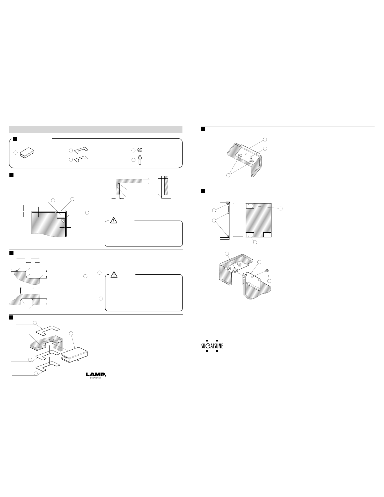
manuals.online logo
Brands
  1. Home
  2. •
  3. Brands
  4. •
  5. Lamp
  6. •
  7. Door Lock
  8. •
  9. Lamp XL-GC02 User manual

Lamp XL-GC02 User manual

1
3
2
1Lock Body Installation      3Hanging Door
Strike plate ④ may be installed on top or bottom panel
of cabinet.
Refer to Figure G. Locked dead bolt will be inserted to
depth beyond strike plate.
Bore a hole(depth 6mm) into top or bottom panel as in
Figure D.
Set the strike plate ④ with wood screws as in Figure E.
Inserting the key unlocks the door and removing
the key locks the door.
Always insert key before closing door.
Failure to do so may cause damage.
・
The applicable thickness of the glass
is 5, 6 or 8mm.
・
If you have any questions on glass
processing, please consult your glazing
company.
Attach the glass door to the cabinet.
Inserting the key ⑤ to the lock body ①stores the
dead bolt in the swing door lock. Close the door with
the key inserted in the lock. After closing door remove
the key and check that the door is locked.
Check that the glass fixing
screws ③ are loosely set in
the lock body ①. Fit the lock
body on the glass door. Insert
the gasket ② between the lock
body and the outer side of the
glass so that the glass does
not get scratched.
Tighten the glass fixing screws.
XL-GC02 Swing Door Lock Installation Manual PAT
注意 警告
注意
注意 警告
注意 警告
警告

指を挟まれない
ように注意
基本形状
注意・警告
注意・警告
半角空き
発火注意
■注意記号
2007.04SEPRINTEDINJAPAN 0282-1
                   Door Processing       
2Strike Plate Installation
1
4
29
3.5
26
2313.5
6
Bottom Panel or
Top Panel
Bottom Panel or
Top Panel
Side
Panel Panel
Side
1
4
4
5
1
The Dead Bolt
2
…Lock Body ×1
 
This figure shows the left-sided design.
The right-sided design is symmetrically
opposite.
…Gasket ×1
…Glass Fixing Screw ×2
…Strike Plate ×1
(Note:Wood Screws Included)
…Key ×2
2
3
4
4
65
40
3
7
xlgcd02.eps
5
ア ー キ テ リ ア 事 業 部 (建築金物・家具金物)
テクノフィールド事業部 (産業機器用機構部品)
大阪支店
仙台営業所
名古屋営業所
福岡営業所
〒101-8633
〒101-8633
〒540-0038
〒980-0014
〒462-0825
〒460-0008
〒812-0016
東京都千代田区岩本町2-5-10
東京都千代田区岩本町2-17-9
大阪府大阪市中央区内淡路町2-2-6
宮城県仙台市青葉区本町1-11-1・8F
愛知県名古屋市北区大曽根3-15-3
愛知県名古屋市中区栄5-28-12・4F
福岡県福岡市博多区博多駅南1-8-31・6F
TEL03(3864)1122
TEL03(3851)1122
TEL06(6910)1122
TEL022(716)1122
TEL052(982)1122
TEL052(238)1122
TEL092(461)1122
(代)
(代)
(代)
(代)
(代)
(代)
(代)
FAX03(3863)6875
FAX03(3861)1621
FAX06(6947)1199
FAX022(716)1124
FAX052(911)2823
FAX052(262)2823
FAX092(461)1123
http://www.sugatsune.co.jp/
ISO9001(JSAQ384)・ISO14001(JSAE597)審査登録
建築金物・家具金物・機構部品

(名古屋営業所は2007年5月下旬までは下記の住所になります。)
1-8-11 HigashiKanda, Chiyoda-ku,
Tokyo 101-8633, Japan
TEL:+81-3-3866-2260 FAX:+81-3-3866-4447
http://www.sugatsune.co.jp
E-mail : [email protected]
For Overseas Customers
SUGATSUNE KOGYO CO., LTD.
ISO9001(JSAQ384) ISO14001(JSAE597) CERTIFICATE.
221 East Selandia Lane,
Carson,CA 90746,U.S.A.
TEL:+1-310-329-6373 FAX:+1-310-329-0819
TOLL FREE:(800) 562-5267 (from U.S.A & Canada only)
http://www.sugatsune.com
E-mail : [email protected]      
For North American Customers
SUGATSUNE AMERICA, INC.
  Parts Structure
注意 警告
注意
注意 警告
注意 警告
警告

指を挟まれない
ように注意
基本形状
注意・警告
注意・警告
半角空き
発火注意
■注意記号
Caution
Caution
Swing Door Lock
Installation
C2 R8
C2
60
25
Thank you for purchasing our product. Read all instructions carefully before installation.
Before starting installation, clear area of any hazardous objects. Be careful to avoid injury.
Using this product without observing the cautions may result in the product failure, accidental
injury or installation failure.
注意 警告
注意
注意 警告
注意 警告
警告

指を挟まれない
ように注意
基本形状
注意・警告
注意・警告
半角空き
発火注意
■注意記号
Caution
Figure A
Figure B
Figure C
View from inside cabinet
Figure F Figure G
Figure D Figure E
−5− −6−
For Hinge Body
Figure B
Figure C
(Upper Right or Lower Left)
1
For Hinge Body
(Lower Right or Upper Left)
2
22
22
45
45
R8
R8
C2 C2
C2
C2
Refer to page 7 Figure L for glass
door processing when wing XL-GC05
Top Plate Glass Hinge Support.
・
Applicable glass door size is within W500 mm ×
H1200mm and the applicable weight is not
more than 12 kg.
・
Applicable glass thickness is 5, 6 or 8 mm.
・
If you have any questions on glass processing,
please consult your glazing company.
Thank you for purchasing our product. Read all instructions carefully before installation.
Before starting installation, clear area of any hazardous objects. Be careful to avoid injury.
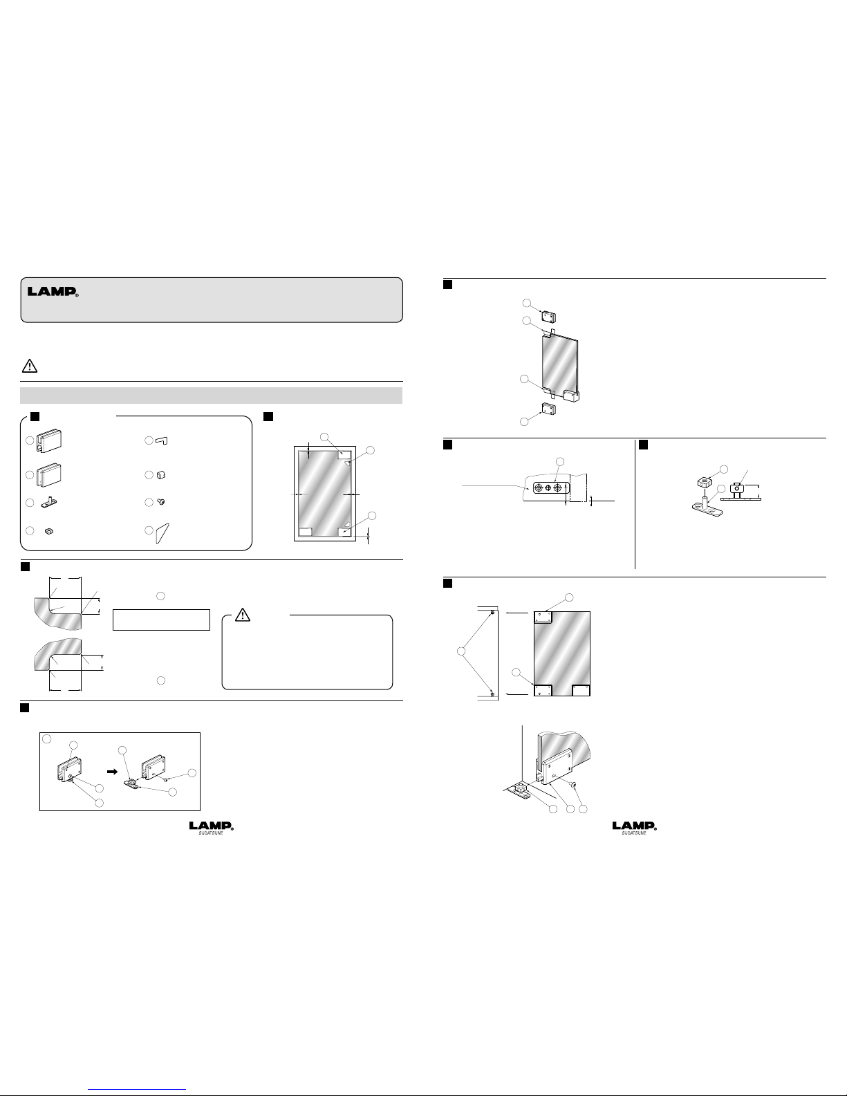
First, open package and check that there are no missing
parts.
Make sure that the glass fixing screws ⑥ are set in
the hinge body ① and ②.
Remove the truss head screws ⑦from the temporarily
assembled hinge body① and ② as shown in Figure
D. Then remove the strike plate ③ and strike plate nut
④.
注意 警告
注意
注意 警告
注意 警告
警告

指を挟まれない
ように注意
基本形状
注意・警告
注意・警告
半角空き
発火注意
■注意記号
XL-GC04 Swing Door Hinge Installation Manual PAT
XL-GC05
Top Plate Glass Hinge Support Installation Manual
PAT
XL-GC04 Swing Door Hinge Installation Manual
Glass Door Processing
1Preparing to Install Hinges
2
…
Hinge Body × 1
 (Upper Right or Lower Left)
…
Hinge Body × 1
 (Lower Right or Upper Left)
…
Strike Plate × 2
 
…Strike Plate Nut ×2
…Gasket × 2
…Glass Fixing Screw×6
…
Truss Head Screw×2
  (M4×8 Cross Recessed)
…Finger Jamming
 
Caution Seal ×2
2
8
1
43
3
3
Glass Door
Figure A
3
7
3
7
4
2
6
Figure D
1
3
4
5
6
7
8
Using this product without observing the cautions may result in the product failure, accidental
injury or installation failure.
注意 警告
注意
注意 警告
注意 警告
警告

指を挟まれない
ように注意
基本形状
注意・警告
注意・警告
半角空き
発火注意
■注意記号
Caution
  Parts Structure   Wood Frame View
  
(Completed Installation)
Caution
(
M4.1×20
Wood Screws Include
)
Set the hinge body ① and ② on the glass door.
Orient the side where screws ⑥ and ⑦ are seen toward the
inside of the cabinet.
Be sure to insert the gasket ⑤ between the hinge body and
glass surface on the outer side of the cabinet.
Refer to Figure G.
Screw the strike plate nuts ④ onto the strike plates ③.
Position nuts on strike plate at 14 mm.
Position the strike plates ③ on the top and bottom panels
so that they touch the side panels.Set strike plates with
the included wood screws.
When using XL-GC05 Top Plate Glass Hinge Support,
install the strike plate on the bottom panel only.
Refer to Figures H and I. Align channel of the hinge
body ① and ② to the strike plate nuts ④. Carefully
slide door over strike plate nuts until the end of the
hinge channel makes contact. If the glass door does
not fit in, or if it does not fit well on the cabinet, pull out
the glass door and turn strike plate nuts ④ to adjust
height.
Refer to Figure I. Strike plate nut ④ has screw holes.
Align hinge body screw hole for truss head screw ⑦
to strike plate nut screw hole. Set door by tightening
truss head screw ⑦. To adjust door position, open
door and loosen truss head screw ⑦. Door can be
adjusted up to 2 mm side to side.
Lastly, affix the finger jamming caution seal ⑧ as
shown in page 5 Figure A.
2Installing Hinges on Glass Door
3Installing Strike Plates         4Setting Strike Plate Nuts
5Hanging Door (Refer to page 7 when using XL-GC05 Top Plate Glass Hinge Support.)
1
5
5
2
Figure E
View from
inside cabinet
3
15.5
Top or Bottom Panel
Inside
cabinet
Outside
cabinet
Figure F
14
3
Screw Position
Figure G
4
Glass door
view from
inside cabinet
view from
inside cabinet
Figure H
Figure I
1
2
7
4
42
−7− −8−
・
Thickness of top plate glass and side plate
glass must be 8 mm.
・
The side plate glass and the top plate glass
must be bonded together securely.
 
UV adhesive is recommended.
Figures J and K show the case of a right-hinged door.
The bottom plate must protrude 4 mm from the glass
side plate.
Refer to Figure M.
Set the aluminum gasket ⑩ and the plastic gaskets ⑪
on the glass as shown.
Then cover with the Top Plate Glass Hinge Support
Unit ⑨ .
・Applicable glass door size is within W500 mm ×
H1200 mm and the applicable weight is not
more than 12 kg.
・Thickness of top plate glass and side plate
glass must be 8 mm.
・For glass processing, please consult your glazing
company.
XL-GC05 Top Plate Glass Hinge Support Installation Manual
注意 警告
注意
注意 警告
注意 警告
警告

指を挟まれない
ように注意
基本形状
注意・警告
注意・警告
半角空き
発火注意
■注意記号
注意 警告
注意
注意 警告
注意 警告
警告

指を挟まれない
ように注意
基本形状
注意・警告
注意・警告
半角空き
発火注意
■注意記号
Glass Frame (Completed Installation)
6Installing the Top Plate Glass Hinge Support Unit on the Top Plate.
Glass Door Processing
3
3
Finger Jamming
Caution Seal
Upper Right Hinge
Glass Top Plate 8mm
XL-GC04 Swing Door Hinge and
Shown :
1
8
9
Glass Door
Figure J
8
8
Adhesive
Glass Side Plate
Bottom
Plate
Glass Top Plate
4
Figure K
4
R8
R8
R8
C2
C2
C2
26
21
76.5
40.5
45
22.75
9
For using Top Plate Glass Hinge Support
and Upper Right Hinge Body 1
9
For using Top Plate Glass Hinge Support
Figure L
Glass Top Plate
Plastic Gasket
Plastic Gasket 11
10
11
9
Aluminum Gasket
Figure M
9…Top Plate Glass Hinge
 Support Unit ×1
…Aluminum Gasket ×1
…Plastic Gasket ×1
…Fixing Screw ×2
…Pivot Pin ×1
10
11
12
13
  Parts Structure
Caution
Caution
2007.04SEPRINTEDINJAPAN 0283-1
7Setting the Top Plate Glass Hinge Support. 
Refer to Figures O and P. Put strike plate nut ④ on
pivot pin ⑬ of top plate glass hinge support ⑨ and
hold in place by hand. Align channel of the hinge body
① and ② to the strike plate nuts ④. Carefully slide
door over strike plate nuts ④ until the end of the hinge
channel makes contact. If the glass door does not fit
in, or if it does not fit well on the cabinet, pull out the
glass door and turn strike plate nuts ④ to adjust
height.
Refer to Figure P. Strike plate nut ④ has screw holes.
Align hinge body screw hole for truss head screw ⑦ to
strike plate nut screw hole. Set door by tightening truss
head screw ⑦. To adjust door position, open door and
loosen truss head screw ⑦. Door can be adjusted up
to 2 mm side to side.
Lastly, affix the finger jamming caution seal ⑧ as
shown on page 7 Figure J.
Tighten fixing screws ⑫with a flat head screwdriver.
8Hanging the Door.
ア ー キ テ リ ア 事 業 部 (建築金物・家具金物)
テクノフィールド事業部 (産業機器用機構部品)
大阪支店
仙台営業所
名古屋営業所
福岡営業所
〒101-8633
〒101-8633
〒540-0038
〒980-0014
〒462-0825
〒460-0008
〒812-0016
東京都千代田区岩本町2-5-10
東京都千代田区岩本町2-17-9
大阪府大阪市中央区内淡路町2-2-6
宮城県仙台市青葉区本町1-11-1・8F
愛知県名古屋市北区大曽根3-15-3
愛知県名古屋市中区栄5-28-12・4F
福岡県福岡市博多区博多駅南1-8-31・6F
TEL03(3864)1122
TEL03(3851)1122
TEL06(6910)1122
TEL022(716)1122
TEL052(982)1122
TEL052(238)1122
TEL092(461)1122
(代)
(代)
(代)
(代)
(代)
(代)
(代)
FAX03(3863)6875
FAX03(3861)1621
FAX06(6947)1199
FAX022(716)1124
FAX052(911)2823
FAX052(262)2823
FAX092(461)1123
http://www.sugatsune.co.jp/
ISO9001(JSAQ384)・ISO14001(JSAE597)審査登録
建築金物・家具金物・機構部品

(名古屋営業所は2007年5月下旬までは下記の住所になります。)
1-8-11 HigashiKanda, Chiyoda-ku,
Tokyo 101-8633, Japan
TEL:+81-3-3866-2260 FAX:+81-3-3866-4447
http://www.sugatsune.co.jp
E-mail : expor[email protected].jp
For Overseas Customers
SUGATSUNE KOGYO CO., LTD.
ISO9001(JSAQ384) ISO14001(JSAE597) CERTIFICATE.
221 East Selandia Lane,
Carson,CA 90746,U.S.A.
TEL:+1-310-329-6373 FAX:+1-310-329-0819
TOLL FREE:(800) 562-5267 (from U.S.A & Canada only)
http://www.sugatsune.com
E-mail : [email protected]      
For North American Customers
SUGATSUNE AMERICA, INC.
9
12
13
1
2
13
4
4
4
7
Figure N
Figure O
Figure P

Other Lamp Door Lock manuals

Lamp ET-48 User manual

Lamp

Lamp ET-48 User manual

Lamp XL-MT120-U01 User manual

Lamp

Lamp XL-MT120-U01 User manual

Lamp XL-GC01 User manual

Lamp

Lamp XL-GC01 User manual

Lamp HC-85SS User manual

Lamp

Lamp HC-85SS User manual

Lamp PKL-07 User manual

Lamp

Lamp PKL-07 User manual

Lamp FD30-F User manual

Lamp

Lamp FD30-F User manual

Lamp GS-GH2 User manual

Lamp

Lamp GS-GH2 User manual

Lamp XL-GC02 User manual

Lamp

Lamp XL-GC02 User manual

Lamp XL-GC02 User manual

Lamp

Lamp XL-GC02 User manual

Popular Door Lock manuals by other brands

Cavity Sliders CAVILOCK BARN DOOR STRIKE installation instructions

Cavity Sliders

Cavity Sliders CAVILOCK BARN DOOR STRIKE installation instructions

Assa Abloy 8788 Installation instruction

Assa Abloy

Assa Abloy 8788 Installation instruction

Dormakaba 9000DE Series installation instructions

Dormakaba

Dormakaba 9000DE Series installation instructions

Digilock Next Cue Product guide

Digilock

Digilock Next Cue Product guide

GEZE SecuLogic RWS TZ 300 Installation and Commissioning Instructions with Wiring Diagram

GEZE

GEZE SecuLogic RWS TZ 300 Installation and Commissioning Instructions with Wiring Diagram

NORMBAU Allegion SRZ 80 PZ Fixing instructions

NORMBAU

NORMBAU Allegion SRZ 80 PZ Fixing instructions

eSSL TL200 Installation instruction

eSSL

eSSL TL200 Installation instruction

Cygnus electronics EL-280 user manual

Cygnus electronics

Cygnus electronics EL-280 user manual

LOCKLY GUARD DEFENDER SLIDE EDITION installation guide

LOCKLY GUARD

LOCKLY GUARD DEFENDER SLIDE EDITION installation guide

Stanley QEL 200 quick start guide

Stanley

Stanley QEL 200 quick start guide

Delf Architectural Deadbolt installation instructions

Delf Architectural

Delf Architectural Deadbolt installation instructions

M&C DCE43M3M Assembly manual

M&C

M&C DCE43M3M Assembly manual

Toledo V190TBIUS15 quick start guide

Toledo

Toledo V190TBIUS15 quick start guide

Commax CDL-1AR user manual

Commax

Commax CDL-1AR user manual

Burg Wächter secuENTRY easy ENTRY 7602 FP Initial setup

Burg Wächter

Burg Wächter secuENTRY easy ENTRY 7602 FP Initial setup

TRU-BOLT 1742006 manual

TRU-BOLT

TRU-BOLT 1742006 manual

danalock DANALOCKV2-BTZU-X Technical manual

danalock

danalock DANALOCKV2-BTZU-X Technical manual

Simplex LP1000 quick start guide

Simplex

Simplex LP1000 quick start guide

manuals.online logo
manuals.online logoBrands
  • About & Mission
  • Contact us
  • Privacy Policy
  • Terms and Conditions

Copyright 2025 Manuals.Online. All Rights Reserved.