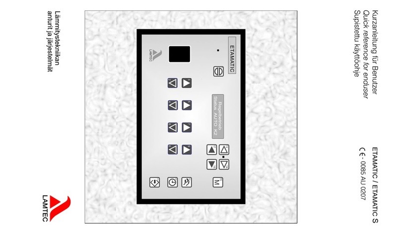
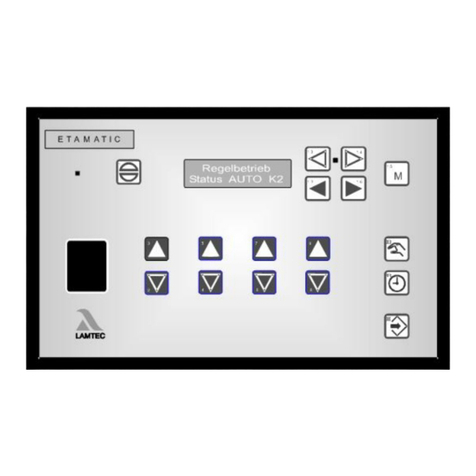
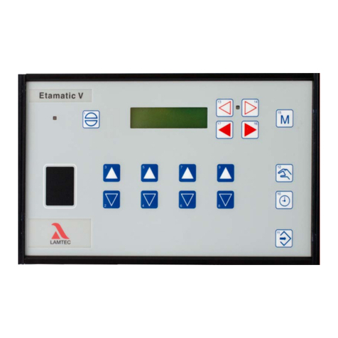
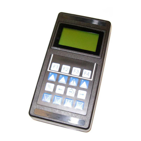
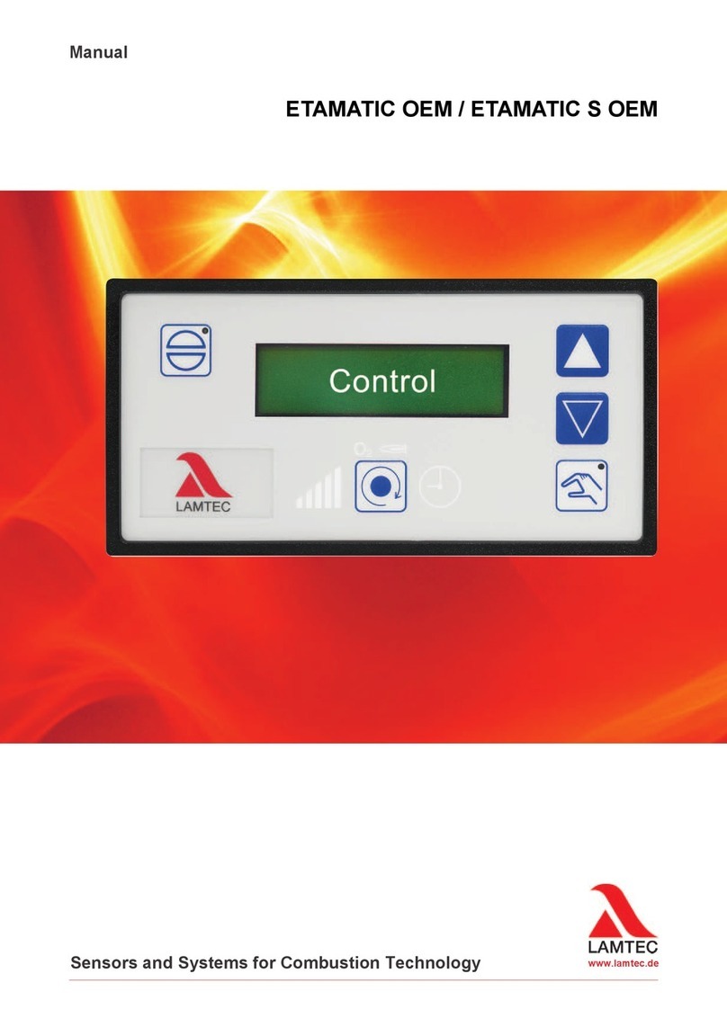
Lamtec ETAMATIC User manual

Manual ETAMATIC / ETAMATIC S
CE-0085 AU 0207
Sensors and Systems
for Combustion Engineering


2
Table of Contents
Table of Contents
1 GENERAL INFORMATION . . . . . . . . . . . . . . . . . . . . . . . . . . . . . . . . . . . . . . . .7
1.1 Validity of these instructions. . . . . . . . . . . . . . . . . . . . . . . . . . . . . . . . . . . . . . . . . . . . . . . . . .7
1.2 Variants - Device Configuration . . . . . . . . . . . . . . . . . . . . . . . . . . . . . . . . . . . . . . . . . . . . . . .8
2 SAFETY. . . . . . . . . . . . . . . . . . . . . . . . . . . . . . . . . . . . . . . . . . . . . . . . . . . . . .10
2.1 German Law on Device Safety . . . . . . . . . . . . . . . . . . . . . . . . . . . . . . . . . . . . . . . . . . . . . . .10
2.2 For Your Safety. . . . . . . . . . . . . . . . . . . . . . . . . . . . . . . . . . . . . . . . . . . . . . . . . . . . . . . . . . . .11
2.3 Associated Automatic Flame Guard. . . . . . . . . . . . . . . . . . . . . . . . . . . . . . . . . . . . . . . . . . .12
3 BRIEF DESCRIPTION. . . . . . . . . . . . . . . . . . . . . . . . . . . . . . . . . . . . . . . . . . .13
3.1 Display and operational controls . . . . . . . . . . . . . . . . . . . . . . . . . . . . . . . . . . . . . . . . . . . . .14
4 OPERATING DESCRIPTION . . . . . . . . . . . . . . . . . . . . . . . . . . . . . . . . . . . . .15
4.1 Starting without pilot burner . . . . . . . . . . . . . . . . . . . . . . . . . . . . . . . . . . . . . . . . . . . . . . . . .15
4.2 Starting with pilot burner. . . . . . . . . . . . . . . . . . . . . . . . . . . . . . . . . . . . . . . . . . . . . . . . . . . .15
5 COMMISSIONING . . . . . . . . . . . . . . . . . . . . . . . . . . . . . . . . . . . . . . . . . . . . . .16
5.1 Before Commissioning . . . . . . . . . . . . . . . . . . . . . . . . . . . . . . . . . . . . . . . . . . . . . . . . . . . . .16
5.1.1 Basic Settings. . . . . . . . . . . . . . . . . . . . . . . . . . . . . . . . . . . . . . . . . . . . . . . . . . . . . . . . 16
5.1.2 Password Entry . . . . . . . . . . . . . . . . . . . . . . . . . . . . . . . . . . . . . . . . . . . . . . . . . . . . . . 16
5.1.3 Select Language. . . . . . . . . . . . . . . . . . . . . . . . . . . . . . . . . . . . . . . . . . . . . . . . . . . . . . 16
5.1.4 Character of the Output Channels . . . . . . . . . . . . . . . . . . . . . . . . . . . . . . . . . . . . . . . . 17
5.1.5 Start with or without pilot burner . . . . . . . . . . . . . . . . . . . . . . . . . . . . . . . . . . . . . . . . . . 19
5.1.6 Pre-ventilation period . . . . . . . . . . . . . . . . . . . . . . . . . . . . . . . . . . . . . . . . . . . . . . . . . . 21
5.1.7 Recirculation Delay. . . . . . . . . . . . . . . . . . . . . . . . . . . . . . . . . . . . . . . . . . . . . . . . . . . . 21
5.1.8 Deactivate load control unit . . . . . . . . . . . . . . . . . . . . . . . . . . . . . . . . . . . . . . . . . . . . . 22
5.1.9 Running Time of the Regular Firing Rate Input with TPS-Input . . . . . . . . . . . . . . . . . . 22
5.1.10 Minimum Running Time of the Compound . . . . . . . . . . . . . . . . . . . . . . . . . . . . . . . . . . 22
5.1.11 Post-ventilation time . . . . . . . . . . . . . . . . . . . . . . . . . . . . . . . . . . . . . . . . . . . . . . . . . . .23
5.1.12 Delaytime of the Air Dampers During Pre-ventilation . . . . . . . . . . . . . . . . . . . . . . . . . . 24
5.1.13 Parameters of the Interface . . . . . . . . . . . . . . . . . . . . . . . . . . . . . . . . . . . . . . . . . . . . . 25
5.1.14 Deactivate leakage test . . . . . . . . . . . . . . . . . . . . . . . . . . . . . . . . . . . . . . . . . . . . . . . . 25
5.1.15 Set pilot burner (maintenance mode) . . . . . . . . . . . . . . . . . . . . . . . . . . . . . . . . . . . . . . 26
5.1.16 Automatic Restart after Failure. . . . . . . . . . . . . . . . . . . . . . . . . . . . . . . . . . . . . . . . . . . 27
5.1.17 Burner Firing Rate Controller . . . . . . . . . . . . . . . . . . . . . . . . . . . . . . . . . . . . . . . . . . . . 28
5.2 Setting . . . . . . . . . . . . . . . . . . . . . . . . . . . . . . . . . . . . . . . . . . . . . . . . . . . . . . . . . . . . . . . . . . .32
5.2.1 Setting the Limit Switches of the Motors . . . . . . . . . . . . . . . . . . . . . . . . . . . . . . . . . . . 32
5.2.2 Adjusting control elements . . . . . . . . . . . . . . . . . . . . . . . . . . . . . . . . . . . . . . . . . . . . . . 32
5.2.3 Programming the Ignition Point . . . . . . . . . . . . . . . . . . . . . . . . . . . . . . . . . . . . . . . . . . 33
5.2.4 Programming the Base Load . . . . . . . . . . . . . . . . . . . . . . . . . . . . . . . . . . . . . . . . . . . . 33
5.2.5 Programming the 3rd up the 10th Point . . . . . . . . . . . . . . . . . . . . . . . . . . . . . . . . . . . . 34
5.2.6 Saving Curve . . . . . . . . . . . . . . . . . . . . . . . . . . . . . . . . . . . . . . . . . . . . . . . . . . . . . . . .34

3
Table of Contents
5.2.7 Changing Points . . . . . . . . . . . . . . . . . . . . . . . . . . . . . . . . . . . . . . . . . . . . . . . . . . . . . . 34
5.2.8 Saving Changes . . . . . . . . . . . . . . . . . . . . . . . . . . . . . . . . . . . . . . . . . . . . . . . . . . . . . . 34
5.3 Fault . . . . . . . . . . . . . . . . . . . . . . . . . . . . . . . . . . . . . . . . . . . . . . . . . . . . . . . . . . . . . . . . . . . . .35
5.3.1 Reading Faults . . . . . . . . . . . . . . . . . . . . . . . . . . . . . . . . . . . . . . . . . . . . . . . . . . . . . . .35
5.3.2 Resetting Faults . . . . . . . . . . . . . . . . . . . . . . . . . . . . . . . . . . . . . . . . . . . . . . . . . . . . . .35
5.3.3 Recall Fault History . . . . . . . . . . . . . . . . . . . . . . . . . . . . . . . . . . . . . . . . . . . . . . . . . . . 35
6 O2-CONTROL . . . . . . . . . . . . . . . . . . . . . . . . . . . . . . . . . . . . . . . . . . . . . . . . .36
6.1 What happens if a fault occurs in the O2 regulation. . . . . . . . . . . . . . . . . . . . . . . . . . . . . .36
6.1.1 How to switch the Display. . . . . . . . . . . . . . . . . . . . . . . . . . . . . . . . . . . . . . . . . . . . . . . 36
6.2 Air Deficiency Pertubation. . . . . . . . . . . . . . . . . . . . . . . . . . . . . . . . . . . . . . . . . . . . . . . . . . .36
6.3 Resetting O2-errors . . . . . . . . . . . . . . . . . . . . . . . . . . . . . . . . . . . . . . . . . . . . . . . . . . . . . . . .36
6.4 Calling Fault History O2-Controller. . . . . . . . . . . . . . . . . . . . . . . . . . . . . . . . . . . . . . . . . . . .37
6.5 How to Change the Password . . . . . . . . . . . . . . . . . . . . . . . . . . . . . . . . . . . . . . . . . . . . . . . .37
6.6 How to switch the Display . . . . . . . . . . . . . . . . . . . . . . . . . . . . . . . . . . . . . . . . . . . . . . . . . . .37
6.7 Automatic Function Monitoring During Operation . . . . . . . . . . . . . . . . . . . . . . . . . . . . . . .38
6.7.1 Test During Burner Start. . . . . . . . . . . . . . . . . . . . . . . . . . . . . . . . . . . . . . . . . . . . . . . . 38
6.7.2 O2 Monitoring Band . . . . . . . . . . . . . . . . . . . . . . . . . . . . . . . . . . . . . . . . . . . . . . . . . . . 38
6.7.3 O2 Boundary Curve . . . . . . . . . . . . . . . . . . . . . . . . . . . . . . . . . . . . . . . . . . . . . . . . . . . 39
6.7.4 Dynamic Probe Test . . . . . . . . . . . . . . . . . . . . . . . . . . . . . . . . . . . . . . . . . . . . . . . . . . . 39
6.8 Control Strategy . . . . . . . . . . . . . . . . . . . . . . . . . . . . . . . . . . . . . . . . . . . . . . . . . . . . . . . . . . .40
6.9 Connecting the O2 Measurement Device. . . . . . . . . . . . . . . . . . . . . . . . . . . . . . . . . . . . . . .41
6.10 Operation and Display of the O2-Controller. . . . . . . . . . . . . . . . . . . . . . . . . . . . . . . . . . . . .42
6.10.1 Display and Interpretation of the Operating Modes . . . . . . . . . . . . . . . . . . . . . . . . . . . 42
6.10.2 Calling up O2 Controller Text Messages . . . . . . . . . . . . . . . . . . . . . . . . . . . . . . . . . . . 43
6.11 Commissioning. . . . . . . . . . . . . . . . . . . . . . . . . . . . . . . . . . . . . . . . . . . . . . . . . . . . . . . . . . . .43
6.11.1 Setting the Correction Range and the Correction Mode. . . . . . . . . . . . . . . . . . . . . . . . 43
6.11.2 Available Correction Modes . . . . . . . . . . . . . . . . . . . . . . . . . . . . . . . . . . . . . . . . . . . . . 43
6.11.3 Correction Type 2 . . . . . . . . . . . . . . . . . . . . . . . . . . . . . . . . . . . . . . . . . . . . . . . . . . . . .44
6.11.4 Setting the Correction Range . . . . . . . . . . . . . . . . . . . . . . . . . . . . . . . . . . . . . . . . . . . . 44
6.11.5 Calling up the Set Correction Mode . . . . . . . . . . . . . . . . . . . . . . . . . . . . . . . . . . . . . . . 45
6.11.6 Checking the Combustion Boundary Values . . . . . . . . . . . . . . . . . . . . . . . . . . . . . . . . 45
6.11.7 O2 curve input . . . . . . . . . . . . . . . . . . . . . . . . . . . . . . . . . . . . . . . . . . . . . . . . . . . . . . . 46
6.12 Calling up Running Time Meter. . . . . . . . . . . . . . . . . . . . . . . . . . . . . . . . . . . . . . . . . . . . . . .50
6.13 Calling up the Checksum. . . . . . . . . . . . . . . . . . . . . . . . . . . . . . . . . . . . . . . . . . . . . . . . . . . .50
6.14 Re-enter Range Limits . . . . . . . . . . . . . . . . . . . . . . . . . . . . . . . . . . . . . . . . . . . . . . . . . . . . . .51
7 INTERNAL BURNER FIRING-RATE CONTROLLER. . . . . . . . . . . . . . . . . . .52
7.1 Purpose . . . . . . . . . . . . . . . . . . . . . . . . . . . . . . . . . . . . . . . . . . . . . . . . . . . . . . . . . . . . . . . . . .52

4
Table of Contents
7.2 Brief Description. . . . . . . . . . . . . . . . . . . . . . . . . . . . . . . . . . . . . . . . . . . . . . . . . . . . . . . . . . .52
7.3 Limit Ranges . . . . . . . . . . . . . . . . . . . . . . . . . . . . . . . . . . . . . . . . . . . . . . . . . . . . . . . . . . . . . .52
7.4 Light Writing "Actual Temperature is too high" . . . . . . . . . . . . . . . . . . . . . . . . . . . . . . . . .52
7.5 Enter setpoint of power control . . . . . . . . . . . . . . . . . . . . . . . . . . . . . . . . . . . . . . . . . . . . . . 52
7.6 Input Signals . . . . . . . . . . . . . . . . . . . . . . . . . . . . . . . . . . . . . . . . . . . . . . . . . . . . . . . . . . . . . .53
7.7 Operating Description . . . . . . . . . . . . . . . . . . . . . . . . . . . . . . . . . . . . . . . . . . . . . . . . . . . . . .53
7.8 Steam Pressure. . . . . . . . . . . . . . . . . . . . . . . . . . . . . . . . . . . . . . . . . . . . . . . . . . . . . . . . . . . .53
7.9 Control by Atmospheric Condition. . . . . . . . . . . . . . . . . . . . . . . . . . . . . . . . . . . . . . . . . . . .54
7.10 Set Point Changeover . . . . . . . . . . . . . . . . . . . . . . . . . . . . . . . . . . . . . . . . . . . . . . . . . . . . . .54
7.11 Start-up Sequence . . . . . . . . . . . . . . . . . . . . . . . . . . . . . . . . . . . . . . . . . . . . . . . . . . . . . . . . . 55
7.12 Thermostat and Control Range. . . . . . . . . . . . . . . . . . . . . . . . . . . . . . . . . . . . . . . . . . . . . . .56
7.13 Manual Control . . . . . . . . . . . . . . . . . . . . . . . . . . . . . . . . . . . . . . . . . . . . . . . . . . . . . . . . . . . .58
7.14 Meaning of the Display. . . . . . . . . . . . . . . . . . . . . . . . . . . . . . . . . . . . . . . . . . . . . . . . . . . . . .58
7.15 How to Adjust the Burner-firing-rate Controller . . . . . . . . . . . . . . . . . . . . . . . . . . . . . . . . .58
7.16 Control Range. . . . . . . . . . . . . . . . . . . . . . . . . . . . . . . . . . . . . . . . . . . . . . . . . . . . . . . . . . . . .59
7.17 Checking of the Safety Limiter . . . . . . . . . . . . . . . . . . . . . . . . . . . . . . . . . . . . . . . . . . . . . . .59
8 CONTROL MODE . . . . . . . . . . . . . . . . . . . . . . . . . . . . . . . . . . . . . . . . . . . . . .60
8.1 Aides for Setting. . . . . . . . . . . . . . . . . . . . . . . . . . . . . . . . . . . . . . . . . . . . . . . . . . . . . . . . . . .61
8.2 Leakage test . . . . . . . . . . . . . . . . . . . . . . . . . . . . . . . . . . . . . . . . . . . . . . . . . . . . . . . . . . . . . .63
8.2.1 Leakage test flow chart. . . . . . . . . . . . . . . . . . . . . . . . . . . . . . . . . . . . . . . . . . . . . . . . . 64
8.2.2 Calculation example . . . . . . . . . . . . . . . . . . . . . . . . . . . . . . . . . . . . . . . . . . . . . . . . . . . 65
8.2.3 Standby . . . . . . . . . . . . . . . . . . . . . . . . . . . . . . . . . . . . . . . . . . . . . . . . . . . . . . . . . . . . 66
9 APPENDIX. . . . . . . . . . . . . . . . . . . . . . . . . . . . . . . . . . . . . . . . . . . . . . . . . . . .69
9.1 Mode Abbreviations Used . . . . . . . . . . . . . . . . . . . . . . . . . . . . . . . . . . . . . . . . . . . . . . . . . . .69
9.2 Flame Monitoring . . . . . . . . . . . . . . . . . . . . . . . . . . . . . . . . . . . . . . . . . . . . . . . . . . . . . . . . . .70
9.2.1 Integral flame monitoring (option). . . . . . . . . . . . . . . . . . . . . . . . . . . . . . . . . . . . . . . . . 70
9.2.2 General Information of the Optical Flame Monitoring. . . . . . . . . . . . . . . . . . . . . . . . . . 71
9.2.3 Optical flame sensors . . . . . . . . . . . . . . . . . . . . . . . . . . . . . . . . . . . . . . . . . . . . . . . . . . 72
9.3 Avoiding EMC Effects . . . . . . . . . . . . . . . . . . . . . . . . . . . . . . . . . . . . . . . . . . . . . . . . . . . . . .72
9.4 Error Codes. . . . . . . . . . . . . . . . . . . . . . . . . . . . . . . . . . . . . . . . . . . . . . . . . . . . . . . . . . . . . . .74
9.5 Aides . . . . . . . . . . . . . . . . . . . . . . . . . . . . . . . . . . . . . . . . . . . . . . . . . . . . . . . . . . . . . . . . . . . .81

5
Table of Contents
9.6 Calling Up the Condition of the Digital Inputs . . . . . . . . . . . . . . . . . . . . . . . . . . . . . . . . . . .87
9.7 Tips and Tricks . . . . . . . . . . . . . . . . . . . . . . . . . . . . . . . . . . . . . . . . . . . . . . . . . . . . . . . . . . . .88
9.7.1 Set pilot burner . . . . . . . . . . . . . . . . . . . . . . . . . . . . . . . . . . . . . . . . . . . . . . . . . . . . . . . 88
9.7.2 Post-measurement of safety times . . . . . . . . . . . . . . . . . . . . . . . . . . . . . . . . . . . . . . . . 88
9.8 Process Sequence Charts . . . . . . . . . . . . . . . . . . . . . . . . . . . . . . . . . . . . . . . . . . . . . . . . . . .89
9.9 Connection Diagrams. . . . . . . . . . . . . . . . . . . . . . . . . . . . . . . . . . . . . . . . . . . . . . . . . . . . . . .97
9.10 Connection Examples Regular Firing Rate Input . . . . . . . . . . . . . . . . . . . . . . . . . . . . . . . .99
9.11 Connection flame monitor and external firing rate controller . . . . . . . . . . . . . . . . . . . . .100
9.12 LAMTEC SYSTEM BUS (LSB) . . . . . . . . . . . . . . . . . . . . . . . . . . . . . . . . . . . . . . . . . . . . . . .101
9.12.1 Configuration of the Processor Board . . . . . . . . . . . . . . . . . . . . . . . . . . . . . . . . . . . . 101
9.12.2 LSB Connection . . . . . . . . . . . . . . . . . . . . . . . . . . . . . . . . . . . . . . . . . . . . . . . . . . . . . 101
9.12.3 LAMTEC SYSTEM BUS Plug. . . . . . . . . . . . . . . . . . . . . . . . . . . . . . . . . . . . . . . . . . . 104
9.13 Modem for Remote Control . . . . . . . . . . . . . . . . . . . . . . . . . . . . . . . . . . . . . . . . . . . . . . . . . 106
9.14 Inernal Connecting Diagram of the Control Output Device . . . . . . . . . . . . . . . . . . . . . . .107
9.15 Exhaust of test line over the roof . . . . . . . . . . . . . . . . . . . . . . . . . . . . . . . . . . . . . . . . . . . .108
9.16 Switch- and Key Combinations. . . . . . . . . . . . . . . . . . . . . . . . . . . . . . . . . . . . . . . . . . . . . .109
9.17 R. P. M. Sensor . . . . . . . . . . . . . . . . . . . . . . . . . . . . . . . . . . . . . . . . . . . . . . . . . . . . . . . . . . .110
9.17.1 Direct connection of the R. P. M. Sensor . . . . . . . . . . . . . . . . . . . . . . . . . . . . . . . . . . 110
9.17.2 Selection of the Suitable R. P. M. Sensor . . . . . . . . . . . . . . . . . . . . . . . . . . . . . . . . . 112
9.18 External Switching of the fuel motors/ valves . . . . . . . . . . . . . . . . . . . . . . . . . . . . . . . . . .114
9.19 Feedback at Three-point-step Outputs. . . . . . . . . . . . . . . . . . . . . . . . . . . . . . . . . . . . . . . .115
9.19.1 Joining with positive locking . . . . . . . . . . . . . . . . . . . . . . . . . . . . . . . . . . . . . . . . . . . . 115
9.19.2 Fail-safe Feedback . . . . . . . . . . . . . . . . . . . . . . . . . . . . . . . . . . . . . . . . . . . . . . . . . . . 115
9.19.3 Examples of potentiometers . . . . . . . . . . . . . . . . . . . . . . . . . . . . . . . . . . . . . . . . . . . . 115
9.20 Changing Control Drives / Potentiometers . . . . . . . . . . . . . . . . . . . . . . . . . . . . . . . . . . . .116
9.20.1 How to replace a servo motor. . . . . . . . . . . . . . . . . . . . . . . . . . . . . . . . . . . . . . . . . . . 116
9.20.2 How to replace a potentiometer . . . . . . . . . . . . . . . . . . . . . . . . . . . . . . . . . . . . . . . . . 117
9.21 Changing EPROMs. . . . . . . . . . . . . . . . . . . . . . . . . . . . . . . . . . . . . . . . . . . . . . . . . . . . . . . .117
9.22 Wiring Notes . . . . . . . . . . . . . . . . . . . . . . . . . . . . . . . . . . . . . . . . . . . . . . . . . . . . . . . . . . . . .119
9.22.1 Connection of the Shields. . . . . . . . . . . . . . . . . . . . . . . . . . . . . . . . . . . . . . . . . . . . . . 119
9.22.2 PE Bus Rail . . . . . . . . . . . . . . . . . . . . . . . . . . . . . . . . . . . . . . . . . . . . . . . . . . . . . . . .119
9.22.3 Control Cabinet Wiring . . . . . . . . . . . . . . . . . . . . . . . . . . . . . . . . . . . . . . . . . . . . . . . . 119
9.23 Run to Shut-off Limits . . . . . . . . . . . . . . . . . . . . . . . . . . . . . . . . . . . . . . . . . . . . . . . . . . . . .120
9.24 Tolerance Limit in Direction Air Deficiency . . . . . . . . . . . . . . . . . . . . . . . . . . . . . . . . . . . . 121
9.24.1 Example of a Protocol of the Parameter Settings of the Monitoring Bands . . . . . . . . 123
9.25 Technical Data . . . . . . . . . . . . . . . . . . . . . . . . . . . . . . . . . . . . . . . . . . . . . . . . . . . . . . . . . . . 124
9.26 ETAMATIC without internal flame monitoring . . . . . . . . . . . . . . . . . . . . . . . . . . . . . . . . . .127

7
1 General Information
1.1 Validity of these instructions
These instructions apply to the ETAMATIC and ETAMATIC S in any configuration.
This devices conform to the following standards and regulations:
EN 230
EN 267 (where applicable)
EN 298
EN 676 (where applicable)
EN 746-2 (where applicable)
EN 12952 -8 u.11 (where applicable)
EN 12953 7 u. 9 (where applicable)
TRD411
TRD412
TRD604
EMC - Directive, Low-Voltage Directive
Pressure equipment directive
Gas Appliance Directive
Test symbols: CE-0085 AU 0207
The ETAMATIC is a control unit for combustion systems.

8
1 General Information
1.2 Variants - Device Configuration
The variant number describes the device's variant. You will find the variant number on the side
of the housing. The variant number is based on the following key:
Example: ETAMATIC in variante no.: 0 0 001 r0 AM S AP
a: Flame monitoring
b: Control by atmospheric condition for PCU / standby operation
c: Analogue in-/output
Serial number
ETAMATIC 0 0 001 r0 AM S AP
abcde f g
1Flame monitoring 50Hz
2Flame monitoring 60Hz
1cont.by atmospheric condition PCU current 4...20 mA passive
2cont.by atmospheric condition PCU PT100 up to 320°C
3cont.by atmospheric condition PCU poti 5 kOHM
4Current correction
5STANDBY-operation if load controller integrated
6STANDBY-operation, activation via fieldbus
7STANDBY-operation, activation via LSB
04x three-point-step output
13x DPS and 1x continues output 4...20 mA, FB 4...20 mA
42x DPS and 2x continues output 4...20 mA, FB 4...20 mA
54x DPS and output of the internal load
10 4x DPS with type switchover channel 1
11 3x DPS & 2x continuous.and with type switchover channel1
21 3x DPS and 1x continuous output 4...20mA, FB RPM-2L, 300-3600 I/min
22 3x DPS and 1x continuous output 4...20mA, FB RPM-2L, 600-7200 I/min
23 3x DPS and 1x continuous output 4...20mA, FB RPM-2L, 30-300 I/min
24 3x DPS and 1x continuous output 4...20mA, FB RPM-2L, 60-600 I/min
21D 3x DPS and 1x continuous output 4...20mA, FB RPM-3L, 300-3600 I/min
22D 3x DPS and 1x continuous output 4...20mA, FB RPM-3L, 600-7200 I/min
23D 3x DPS and 1x continuous output 4...20mA, FB RPM-3L, 30-300 I/min
24D 3x DPS and 1x continuous output 4...20mA, FB RPM-3L, 60-600 I/min

9
1 General Information
d: O2/ CO control
e: Customer
f: Connector set
g: Output relais fault
21D 2x DPS and 2x continuous output 4...20mA, FB C1 RPM-3L, 300-3600 I/min
31D 2x DPS and 2x continuous output 4...20mA, FB C1 RPM-3L, 300-3600 I/min
r0 O2controller via LAMTEC SYSTEM BUS
r2 O2controller via external system
r3 O2/CO controller
r4 O2controller and correction forwarding master
r5 O2controller and correction forwarding slave
r6 O2/CO controller and correction forwarding master
r7 O2/CO controller and correction forwarding slave
FED Connector set spring tension
INV Connector set invers
SConnector set standard
AP Output relais fault normally open
RP Output relais fault normally closed

10
2 Safety
2 Safety
2.1 German Law on Device Safety
The legislation on safety of appliances states:
Follow the instructions!
Proceed only in accordance with this ETAMATIC commissioning supplement (print no
DLT2001-11-aEN-184)
Use the equipment for the purpose described!
Operating by trained personnel only.
The appliance may only be operated and serviced by personnel with the required knowledge
and education to do so on the conditions and safety rules.
Follow the safety instructions of the burner manufacturer.
To be used in grounded power line network only!
If a flame monitor, which is not approved for continuous operation, is connected up, the ap-
proval for continuous operation of the system will be rendered invalid.
The unit is approved for use only with an external automatic flame guard. The automatic flame
guard type F 250 made by LAMTEC is used for testing purposes.
The following flame monitoring systems / flame sensors are applicable for use
(see the print no. of the associated documents in brackets behind the devices):
Compact flame detector F200 K1 and F200 K2(DLT 7620)
Flame monitoring system F150 (DLT 7521) and F250 (DLT 7540) in conjunction with the flame
sensors FFS05 / FFS05 Ex / FFS05 ExII (DLT 7501 and DLT 7503) and FFS06 (DLT 7502)
Any other automatic flame guard tested in accordance with DIN EN 298 and/or DIN EN 230
and approved for continuous operation may be used instead of this.
Before using a flame sensor / flame monitoring system you have to study the associated man-
ual. Pay attention to the specifications and observe the instructions.
Electric connection to devices, which are not mentioned in these instructions only after con-
sultation with the manufacturer or a qualified expert. If an automatic flame guard which is not
approved for continuous operation is connected, the system will loose the approval for contin-
uous operation. Liability for proper functioning of the appliance passes to the owner or opera-
tor. Liability for correct functioning of the appliances in every case passes to the owner or
operator, should the appliance be incorrectly operated, serviced or repaired by persons with-
out the requisite knowledge, or if operation is inconsistent with the specified intended purpose.
In the event of modifications to the unit the type approval lapses. The unit's inputs and outputs
and associated modules must only be wired according to the specifications in these instruc-
tions.
LAMTEC GmbH & Co KG will not be liable for damage or injury arising out of a failure to ob-
serve the instructions above. The warranty and liability provisions of the terms and conditions
of sale and supply of LAMTEC GmbH & Co KG shall not be extended by virtue of the instruc-
tions above.
LAMTEC GmbH & Co KG will not be liable for damage or injury arising out of a failure to ob-
serve the instructions above. The warranty and liability provisions of the terms and conditions
of sale and supply of LAMTEC GmbH & Co KG shall not be extended by virtue of the instruc-
tions above.
Where reference is made to legislation, government regulations and standards, these are
based on the legal system of the Republic of Germany

11
2 Safety
2.2 For Your Safety
In this operating instructions, the following symbols are used as important safety instructions
to the user. These symbols appear wherever there is a need for this information in a particular
section.
It is essential to note and comply with the safety instructions, particularly the warnings.
DANGER!
Indicates possible danger to personnel, particularly with regard to electrical equipment
WARNING!
Indicates possible danger to personnel if the system components are not handled correctly.
CAUTION!
Indicates danger to system components or possible impairment of functionality.
NOTICE!
Contains important additional information for the user concerning the system or system com-
ponents and provides helpful tips
Contained in texts that provide information on how to perform tasks.
In performing all tasks, the operator is requested to observe all statutory safety regulations
and to do everything possible, according to the circumstances, to prevent injury to persons or
damage to equipment

12
2 Safety
2.3 Associated Automatic Flame Guard
The unit is available with and without an integral flame guard. Sensor types FFS 06, FFS 05
and FFS 05UV can be connected to the integral flame guard. When used without integral
flame guard, any tested flame guard in accordance with DIN EN 298 and/or DIN EN 230 and
approval for continuous operation may be connected to terminal 53 like the following (docu-
ment no. in brackets):
Compact flame detector F200 K1 and K2 (DLT7620) or the flame guards F150 (DLT7521) and
F250 (DLT7540) with the flame sensors FFS05 / FFS05 EX / FFS05 ExI (DLT7501 and
DLT7503) and FFS06 (DLT7502)
WARNING!
If the ETAMATIC is used with an integral flame guard, terminal 53 must not be connected to
any other components.
WARNING!
Electrical connection to appliances not listed in these instructions: only after consultation with
the manufacturers or a qualified expert.
If a flame guard, which is not approved for continuous operation, is connected, the approval
of the system for continuous operation expires.
Liability for proper functioning of the unit passes to the owner or operator.
If the unit is incorrectly operated, serviced or repaired by unqualified personnel, or if operation
is inconsistent with the specified intended purpose, liability for the unit’s correct functioning in
each case passes to the owner or operator.)
WARNING!
The type approval lapses in the event of modifications to the unit. The unit's inputs and outputs
must only be wired according to the specifications in these instructions.
LAMTEC GmbH & Co KG will not be liable for damage or injury arising out of a failure to ob-
serve the instructions above. The warranty and liability provisions contained in LAMTEC
GmbH & Co KG’s terms and conditions for and Supply, shall not be extended by virtue of the
instructions above.
Where reference is made to legislation, government regulations and standards, these are
based on the legal system of the Federal Republic of Germany.

13
3 Brief Description
3 Brief Description
The ETAMATIC regulates up to 4 control elements as a function of a control variable, in ac-
cordance with freely programmable curves. The ETAMATIC has 4 three-point step control out-
puts. The ETAMATIC S has 3 three-point step control outputs and one 4-20 mA output.
Examples of possible control elements:
• combustion air damper
• combustion air fan (ETAMATIC S only)
• fuel valve
• recirculation damper
Up to 20 points (usual 11) can be programmed per channel. The Display is relative between
0 and 999.
The ETAMATIC has a 25-pole Sub-D connector with serial interface for remote operation / re-
mote display via a PC (Windows software available separately). Connections for Interbus-S,
PROFIBUS-DP, CANopen, TCP/IP (Modbus TCP) and Modbus are available as optional
equipment. Other BUS-systems available on enquiry. The connection of other plant compo-
nents, e.g. fault signal systems and O2trim, is via the LAMTEC SYSTEM BUS interface to a
9-pole Sub-D connector.
Operation is via a front panel laminated keyboard. The parameters are displayed on a 2-row
LCD screen.
The ETAMATIC is also available as a special version without a front panel. In this case, oper-
ation is via optional PC software or programming unit. As display for end-user, a customers
interface is connectable via LAMTEC SYSTEM BUS.
The ETAMATIC continuously monitors its own functions and those of the connected control
elements.
230-V outputs:
• Actuation of the gas valves
• Actuation of the oil valves
• Actuation of the oil pump
• Actuation of the ignition valve and the ignition transformer
• Fan release
• Fault message
• Open/Close control signals for the valve/damper motors
External signals to the ETAMATIC are transmitted via floating contacts or chains of contacts.
The following signals can be pre-set:
• 3 separate safety interlock circuits
• fault release
• air pressure monitor
• control release
• min. gas pressure monitor (for leakage test)
• flame signal
• ignition position acknowledgement
• re-circulation on
• burner on
• select fuel
• set-point switching (for load regulator)

14
3 Brief Description
3.1 Display and operational controls
Select operating modes: UEAN PARA O21)AUTO SPLO *
Select operating parameters Status Firing-rate rating Setpoint Actual value feedback Setpoint
feedback 2)digital inputs
Changing dis-
play
– compound
–O
2
– flame in-
tensity
* UEAN = Display of monitoring processor
PARA = Parameterisation
AUTO = Automatic
EINS = Set
SPLO = Clear memory
1) only if activated in the parameter section
2) only in ETAMATIC S

15
4 Operating Description
(for specimen diagrams, see Appendix 9.8 Process Sequence Charts)
A signal is first fed to terminal 58 (Burner On) indicating when the burner is to start.
The ETAMATIC then interrogates the boiler safety interlock circuit or the common safety inter-
lock chain (ETAMATIC) and the contact of the air pressure monitor. If it does not detect an
"OK" condition, the text of a corresponding message appears and the operating control stops.
If all signals are OK, the fan output is activated and the ducts run to their bottom stop as a
check.
Once all channels have reached their bottom stop, they open for aeration. The leakage test
runs in parallel (gas operation only).
In the case of control elements the aeration is used to enter and/or test the range limits. After
reaching its top position, the fuel control element runs back into the ignition position. All other
channels remain in open position. The ETAMATIC then interrogates the air pressure monitor.
If this signal is OK, the parameterised aeration time runs. If a channel is configured for re-cir-
culation, it opens with a time-delay. On reaching the parameterised re-circulation delay time,
the aeration time stops. As soon as the re-circulation channel has reached the aeration posi-
tion, the aeration time is resumed. When this time has expired all the channels run to the pro-
grammed ignition position (re-circulation fully closed). After the lapse of the aeration time, all
channels run to the programmed ignition position (recirculation closed)
4.1 Starting without pilot burner
The main valves open and together with the ignition transformer remain activated for the du-
ration of the safety time. During this time the flame signal appears.
4.2 Starting with pilot burner
The ignition valve and main gas 1 (in gas operation) or the ignition valve alone (in oil operation)
run open. The pilot flame forms and the flame detection detects the flame. The flame detection
sends the signal to the burner control device.
On expiry of the 1st safety time, the ignition transformer switches off. For 3 sec. (stabilisation
time) the pilot burner burns alone. Then main gas 2 or the oil valve opens and remains acti-
vated in parallel with the ignition valve for the duration of the 2nd safety time. The ignition valve
closes again at the end of this period.
3 seconds after ignition, all channels run to the programmed base load point. The ETAMATIC
remains in base load position until control release is given.
After control release the ETAMATIC follows the power control unit’s default setting.
A shut off follows the cancelling of the signal of the terminal 58. The main valves close. In gas
operation, first main gas 1 and second main gas 2 closes with a delay of approx. 5 sec., in
order to allow the test line between the solenoid valves to burn out. In the event of a fault shut-
down, both close immediately.
If configured for post-ventilation, the air channels open again for this period.
Thereafter the ETAMATIC is in the "OFF" mode.

16
5 Commissioning
5 Commissioning
5.1 Before Commissioning
5.1.1 Basic Settings
First you must configure the device (ETAMATIC) for the requirements of the system.
Therefore, you have to set some parameters.
The factory standard settings are indicated by *.
We recommend to use the LAMTEC PC software for Windows (available separately).
5.1.2 Password Entry
5.1.3 Select Language
Select parameter 833
There are only 5 languages available in a single EPROM. The availability of languages de-
pends on the version of the EPROM. For more information refer to the parameter list
(DLT1045).
Press key 1
Press keys 5 and 7 and 8 simultaneously.
Press keys 2 to 9 to enter the password (condition on delivery 0000)
Press key 11 (ENTER)
LED between the keys 13 and 14 is on ( i.e. keys are working).
Press keys 13 or 14 to set the display to "Parameters".
Press keys 6 or 7 to select the required parameter.
Press keys 8 or 9 to change the content.
Value Language Value Language Value Language
0 German* 8 Danish 16 Coal-Gas-English
1 English 9 Portuguese 17 Slovene
2 French 10 Polish 18 Czech
3 Italian 11 Turk 19 Coal-Oil-French
4 Swedish 12 Croatian 20 Coal-Gas-French
5 Spanish 13 Cole-Oil-German 21 Hungarian
6 Dutch 14 Coal-Oil-English 22 Romanian
7 Slovak 15 Coal-Gas-German

17
5 Commissioning
5.1.4 Character of the Output Channels
Select parameter 356 - 359 (channel 1 to channel 4).
Enter the type of control element which is connected.
No FMS ETA Short Text Description Min Max Default
356 2 2 Fkt. K Function definition channel1 0 6
Category = channel configuration and broken wire
detection
In this parameter you define the type of actuator the
respective output channel controls. This indirectly deter-
mines the channel’s behaviour at pre-ventilation, at
band shifting, at changes of the burner-firing rate and at
drift compensation. This possibly may, affect special
functions (e.g. if the channel is configured to recircula-
tion or flue gas).
0 = Channel OFF (broken wire monitoring and
indication in the display are active further on /
channel switch off with P 366 - P 373)
1 = recirculation
2 = fuel
3 = combustion air
4 = flue gas
5 = mechanic compound
6 = atomizer steam (like fuel, but without pre-ventila-
tion of the channel: switch off determination
of range limits)
Behaviour of the actuators with FMS:
steam = Remains CLOSE until the pre-ventilation time
has expired. After that the actuator runs to
ignition position.
REZI = Runs OPEN after the configured pre-ventila-
tion time, even if terminal 6 has a signal. In reg-
ular operation terminal 6 must have a signal.
flue gas = Runs completely open in BE and remains
open until ignition. Then the actuator runs to
compound. At start without VO, ignition starts
not until flue gas is completely open.
mech. compound = Acts like air in VO.
Behaviour of the actuators with VMS:
steam = Remains CLOSE until the pre-ventilation time
has expired. After that the actuator runs to
ignition position.
REZI = runs open to the configured number of points
in VO = position, which the allocated air actua-
tor must have reached (terminal 6 has signal).
flue gas = Runs completely open in BE and remains
open
until ignition. Then the actuator runs to com-
pound. At start without VO, ignition starts not
until flue gas is completely open.
mech. compound = Acts like air in VO.
Default settings at delivery:
channel 1 = air
channel 2 = fuel (oil)
channel 3 = fuel (gas)
channel 4 = air

18
5 Commissioning
Selection, which channel is active
Select parameter 366 and 367 (curve set 1 and 2).
Controller release with bit pattern.
No FMS ETA Short Text Description Min Max Default
366 2 2 K Enb. 1 Channel enable for curve set 1 0 31 15/31
This parameter defines, which channel is active with
which curve set. All channels are active by default (con-
tent 31, for ETAMATIC 15). The following function may
be realised. Example:
changing channel activities with fuel oil/gas
emergency operation with or without frequency con-
verter
Selection per binary pattern:
decimal 15, all 4 channels are released for operation
decimal 31, all 5 channels are released for operation
Example:
Channel 1, 2 and 5 are released
Default settings at delivery:
curve set 1 (oil) = 1001
curve set 2 (gas) = 1101

19
5 Commissioning
5.1.5 Start with or without pilot burner
Select parameter no. 774 and 775 (oil operation, gas operation).
NOTICE!
2 to 4, 9, 11, 17, 19, 25, 27 The ignition flame input must monitor the ignition flame sep-
arately and P 788 must be set to 1.
9, 11 FMS only
17, 19, 25, 27 FMS with mixed fuel firing only
No FMS ETA Short Text Description Min Max Default
774 1 1 ZüBr. ÖL Start with (1) or without (0) pilot burner for oil, (2)=oil
with continuous ignition flame
041
0 = start without pilot burner - oil operation
1 = start with pilot burner - oil operation
2 = pilot burner also active in burner operation with
continuous monitoring of the ignition flame.
Therefore P 788 has to be set to 1
3 = start with pilot burner - oil operation,
only the ignition flame may be present during ignition
(until the 2nd safety time)
4 = pilot burner also active in operation with continuous
operation monitoring of the ignition flame, only the
ignition flame may be present during ignition
(until the 2nd safety time)
(from v. 5.4/510 on)
9 = start with pilot burner - oil operation
You may start the pilot burner with terminal 70 dur-
ing operation.
11 = start with pilot burner - oil operation
only the ignition flame may be present during igni-
tion (until the 2nd safety time).
You may start the pilot burner with terminal 70 dur-
ing operation.
17 = start with pilot burner - oil operation
Before curve set change from solo operation (gas/
fuelA) to mixed mode (+oil), the pilot burner starts
to ignite oil.
19 = start with pilot burner - oil operation,
only the ignition flame may be present during igni-
tion (until the 2nd safety time).
Before curve set change from solo operation (gas/
fuelA) to mixed mode (+oil), the pilot burner starts
to ignite oil.
25 = start with pilot burner - oil operation,
You may start the pilot burner with terminal 70 dur-
ing operation.
Before curve set change from solo operation (gas/
fuelA) to mixed mode (+oil), the pilot burner starts
to ignite oil.
27 = start with pilot burner - oil operation,
only the ignition flame may be present during igni-
tion (until the 2nd safety time).
You may start the pilot burner with terminal 70 dur-
ing operation. Before curve set change from solo
operation (gas/fuelA) to mixed mode (+oil), the pilot
burner starts to ignite oil
Other manuals for ETAMATIC
3
This manual suits for next models
1
Table of contents
Other Lamtec Control Unit manuals
Popular Control Unit manuals by other brands

Sony
Sony MB0402C2 user manual

Bosch
Bosch Rexroth DB 52 3X E Series operating instructions

Klark Teknik
Klark Teknik DN32-DANTE quick start guide

PDi
PDi PD196-244R12 Installation and operating instructions

WAGO
WAGO 751-5701 manual

Cameron
Cameron WHEATLEY 820 Series Installation, operation and maintenance manual