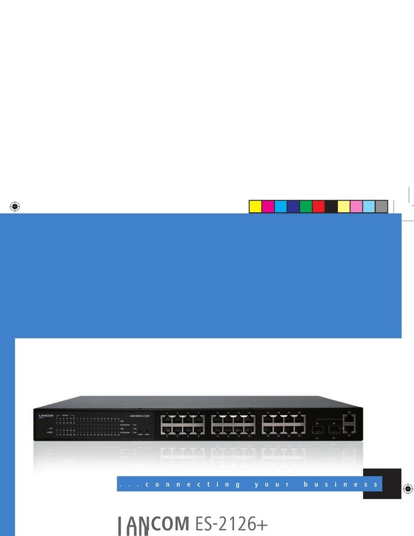
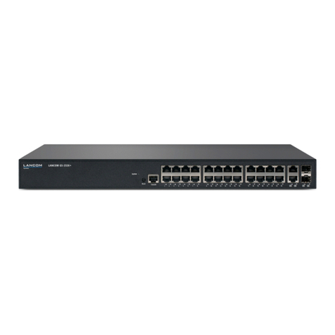
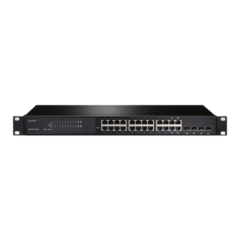
Lancom GS-3528X User manual

1
LANCOM Installation Guide – Copyright
EN
Copyright
© 2020 LANCOM Systems GmbH, Wuerselen (Germany). All rights reserved.
While the information in this manual has been compiled with great care, it may not be deemed an
assurance of product characteristics. LANCOM Systems shall be liable only to the degree specified
in the terms of sale and delivery.
The reproduction and distribution of the documentation and software supplied with this product
and the use of its contents is subject to written authorization from LANCOM Systems. We reserve
the right to make any alterations that arise as the result of technical development.
Windows® and Microsoft® are registered trademarks of Microsoft, Corp.
LANCOM, LANCOM Systems, LCOS, LANcommunity and Hyper Integration are registered
trademarks. All other names or descriptions used may be trademarks or registered trademarks
of their owners. This document contains statements relating to future products and their
attributes. LANCOM Systems reserves the right to change these without notice. No liability for
technical errors and/ or omissions.
Products from LANCOM Systems include software developed by the “OpenSSL Project” for use in
the “OpenSSL Toolkit” (www.openssl.org).
Products from LANCOM Systems include cryptographic software written by Eric Young (eay@
cryptsoft.com).
Products from LANCOM Systems include software developed by the NetBSD Foundation, Inc. and
its contributors.
Products from LANCOM Systems contain the LZMA SDK developed by Igor Pavlov.
LANCOM Systems GmbH
Adenauerstr. 20/B2
52146 Wuerselen
Germany
www.lancom-systems.com/
Wuerselen, 04/2020

2
LANCOM Installation Guide – Introduction
EN
Introduction
Overview
LANCOM switches are the foundation for a reliable infrastructure. These
switches deliver multiple intelligent features for improving the availability
of your critical business applications, protecting your data, and optimizing
your network bandwidth to deliver information and applications more
effectively. Easy to set up and use, they provide the ideal combination of
economic efficiency and technical capabilites from entry level to enter-
prise level networks. All models offer enhanced security and management
functions. In addition, they have networking features to support common
applications of data, voice, security and wireless networking.
Switch architecture
The switches performs a wire-speed, non-blocking switching fabric. This
allows wire-speed transport of multiple packets at low latency on all ports
simultaneously. The switch also features full-duplex capability on all ports,
which effectively doubles the bandwidth of each connection. The switches
use store-and-forward technology to ensure maximum data integrity.
With this technology, the entire packet must be received into a buffer and
checked for validity before being forwarded. This prevents errors from
being propagated throughout the network.

3
LANCOM Installation Guide – Introduction
EN
Network management
LANCOM Systems offers three types of switches: unmanaged switches,
websmart switches, and managed switches.
AUnmanaged switches are not configurable.
AWebsmart switches are configurable only by their web-based GUI.
Additionally, these switches offer an integrated network management
agent, which allows managing via SNMP or RMON (Groups 1, 2, 3, 9).
AManaged switches support configuration via LANCOM Management
Cloud (LMC), a web-based GUI, or CLI (Command Line Interface via SSH
or Telnet). For outband management, these switches either provide a
front-sided RJ45 console port, or a serial port at the front- or backside
of the device. This port can be used for connecting a null-modem cable
to a PC for configuration and monitoring purposes.
4A LANCOM switch automatically contacts the LMC for 24 hours
after startup (boot / reset) to successfully terminate the coupling.
This enables zero-touch deployment for operation with the LMC.
Configuration options overview
LMC CLI Outband Web-based
Unmanaged switch — — — —
Websmart switch — — — 1
Managed switch 1 1 1 1

4
LANCOM Installation Guide – Safety instructions and intended use
EN
Safety instructions and intended use
5In order to avoid harming yourself, third parties or your equipment
when installing your LANCOM device, please observe the following
safety instructions. Operate the device only as described in the ac-
companying documentation. Pay particular attention to all warnings
and safety instructions. Use only those third-party devices and com-
ponents that are recommended or approved by LANCOM Systems.
Before commissioning the device, be sure to study the Quick Reference
Guide supplied with the hardware. These can also be downloaded from
the LANCOM website (www.lancom-systems.com).
Any warranty and liability claims against LANCOM Systems are excluded
following any usage other than the intended use described below.
Environment
LANCOM devices should only be operated when the following environ-
mental requirements are met:
AEnsure that you comply with the temperature and humidity ranges
specified in the Quick Reference Guide for the LANCOM device.
ADo not expose the device to direct sunlight.
AEnsure that there is adequate air circulation and do not obstruct the
ventilation slots.
ADo not cover devices or stack them on top of one another
AThe device must be mounted so that it is freely accessible (for example,
it should be accessible without the use of technical aids such as
elevating platforms); a permanent installation (e.g. under plaster) is not
permitted.

5
LANCOM Installation Guide – Safety instructions and intended use
EN
Power supply
Please observe the following before installation, as improper use can lead
to personal injury and damage to property, as well as voiding the warranty:
AUse only the power adapter / IEC power cable mentioned in the Quick
Reference Guide.
ASome models can be powered via the Ethernet cable (Power-over-
Ethernet, PoE). Please observe the relevant instructions in the Quick
Reference Guide for the device.
ANever operate damaged components.
ATurn the device on only if the housing is closed.
AThe device must not be installed during thunderstorms and should be
disconnected from the power supply during thunderstorms.
AIn emergency situations (e.g. in the case of damage, ingress of liquids
or objects, for example through the ventilation slots), the power supply
must be disconnected immediately.
AOperate the device only with a professionally installed power supply at
a nearby and any time accessible power outlet.
Applications
AThe devices may only be used in accordance with the relevant national
regulations and under consideration of the legal situation applicable
there.
AThe devices must not be used for the actuation, control, and data
transmission of machinery that, in case of malfunction or failure, may
present a danger to life and limb, nor for the operation of critical
infrastructures.
6
LANCOM Installation Guide – Safety instructions and intended use
EN
AThe devices with their respective software are not designed, intended
or certified for use in: the operation of weapons, weapons systems,
nuclear facilities, mass transportation, autonomous vehicles, aircraft,
life support computers or equipment (including resuscitators and
surgical implants), pollution control, hazardous materials management,
or other hazardous applications where failure of the device or software
could lead to a situation in which personal injury or death could result.
The customer is aware that the use of the devices or software in such
applications is entirely at the customer‘s risk.
General safety
AUnder no circumstances should the device housing be opened and the
device repaired without authorization. Any device with a case that has
been opened is excluded from the warranty.
ANotes on the individual interfaces, switches, and displays on your
device are available in the supplied Quick Reference Guide.
AMounting, installation, and commissioning of the device may only be
carried out by qualified personnel.

7
LANCOM Installation Guide – Installation
EN
Installation
For safe and secure installation of your LANCOM device, please observe
the safety instructions and intended use.
Selecting a site
The switch can be mounted in a standard 19-inch equipment rack or on
a flat surface. Be sure to follow the guidelines below when choosing a
location.
APosition the switch near the devices you want to link and near a power
outlet.
ABe able to maintain the temperature of the switch within the limits
listed in the Hardware Quick Reference Guide.
AHave the switch accessible for installing, cabling, and maintaining the
devices.
AAllow the status LEDs to be clearly visible
5Make sure that one rack slot is left free above and below for air
circulation when installing the device in a rack.
5Make sure the twisted-pair Ethernet cable is always routed away
from power lines, radios, transmitters or any other electrical inter-
ference.
5Make sure that the switch is connected to a separate grounded
power outlet that provides 100 to 240VAC, 50 to 60Hz

8
LANCOM Installation Guide – Installation
EN
Ethernet cabling
To ensure proper operation when installing the switch into a network, make
sure that the available cables are suitable for 100BASE-TX or 1000BASE-T
operation. Check the following criteria against the current installation of
your network:
ACable type: Unshielded twisted pair (UTP) or shielded twisted pair (STP)
cable with RJ-45 connectors; Category 5e with maximum length of
100 meters is recommended for 100BASE-TX, and Category 5e or 6
with maximum length of 100 meters is recommended for 1000BASE-T
AProtection from radio frequency interference emissions
AElectrical surge suppression
ASeparation of electrical wires and data – based network wiring
ASafe connections with no damaged cables, connectors or shields
Package content and accessories
Before beginning with the installation, please check that nothing is missing
from your package. Along with the LANCOM switch the box should contain
the following accessories:
APower cord
A19’’ adapter (2 pieces) and mounting materials
ASerial cable (model dependent)
APrinted documentation

9
LANCOM Installation Guide – Installation
EN
Should anything be missing, please immediately contact your dealer or the
address on the delivery note supplied with your device. Ensure that you
have all accessories at hand which might be required during installation.
Mounting and connecting the LANCOM switch
Installing the LANCOM switch involves the following steps:
AMounting – The device is designed for mounting in an available 19”
unit in a server cabinet. Make use of the supplied mounting brackets
for 19“ cabinets. If necessary fix the rubber pads to the underside of
the device to prevent any scratching to other equipment.
5Ensure that the device has sufficient ventilation to prevent damage
from excessive heat build-up.
ALAN connection – Connect the network devices to the ports of the
LANCOM switch by means of a suitable twisted-pair cable (TP cable).
The connectors automatically detect the available data transfer speeds
and the pin assignment (autosensing).
4Use only standard TP cables of category CAT 5 or better with a
maximum length of 100 m to ensure the best possible data transfer.
Crossover cables can be used thanks to the auto-sensing function.

10
LANCOM Installation Guide – Installation
EN
ASupply power – Supply power to the device by means of the IEC power
cable and/or an external power supply unit (model dependent).
AReady for operation? – After a brief self-test, the power or system LED
lights up continuously. Green Link / Act LEDs show which LAN connec-
tors are used for a connection.

11
LANCOM Installation Guide – Configuration
EN
Configuration
Configuration options for websmart and managed
switches
There are three different options to configure the device:
AVia a graphical user interface in a browser (WEBconfig):
This configuraton option (for websmart- and managed switches) is only
available if you have network access to the device’s IP address from
your computer.
AVia a graphical user interface in a browser (LANCOM Management
Cloud – LMC):
This configuration option (only for managed switches) is only available
if you have network access and both your device for configuration and
the switch have a connection to the LANCOM Management Cloud.
AConfiguration via console (Command Line Interface – CLI):
This method of configuration (only for managed switches), which
requires a program such as SSH, Telnet, Hyperterminal, or similar, can
be conducted over a network connection or with a direct connection
via serial interface (RS-232 / RJ45).

12
LANCOM Installation Guide – Configuration
EN
WEBconfig
There are two ways of starting the configuration by browser:
AIf you know the device’s IP address, simply enter this into the address
line of the browser. The factory settings for accessing the device are:
ABefore LCOS SX 4.00: User name: admin, password: admin
AAs from LCOS SX 4.00: User name: admin, password: <empty>
AIf you do not have the device’s IP address, LANconfig can be used to
search for it. LANconfig automatically searches for all available devices
in your network. Any available LANCOM routers or access points will be
displayed in the list, including LANCOM switches. Double-click on this
entry to start the browser automatically with the correct IP address.
What is the IP address of my LANCOM switch?
The current IP address of the LANCOM switch after being switched on
depends on the network constellation.
Aa Networks with DHCP server – In its factory settings, the LANCOM
switch is set for auto DHCP mode, meaning that it searches for a DHCP
server to assign it an IP address, subnet mask and gateway address.
The assigned IP address can only be determined by using the appro-
priate tools (e. g. LANconfig) or via DHCP server. If the DHCP server is
a LANCOM device, the IP address of the LANCOM switch can be read
out from the DHCP table. If this is the case, the LANCOM switch can be
accessed from any network computer that receives its IP address from
the same DHCP server.
ANetwork without a DHCP server – If no DHCP server is present in the
network, the LANCOM switch adopts the address 172.23.56.250. If
this is the case the LANCOM switch can be accessed from any network
computer with its IP address set to the address range 172.23.56.x.

13
LANCOM Installation Guide – Configuration
EN
LANCOM Management Cloud
In order to configure a LANCOM switch via the LANCOM Management
Cloud (LMC), it must first be integrated into the LMC.
Integrating the switch into the LMC requires the switch to be connected to
the Internet and able to reach cloud.lancom.de.
There are two different methods of integrating a LANCOM device into the
LANCOM Management Cloud:
AIntegration into the LANCOM Management Cloud by serial number and
Cloud PIN
AIntegration into the LANCOM Management Cloud by activation code
Integration into the LMC by serial number and Cloud PIN
If you have purchased a LANCOM switch that was shipped with LCOS SX
(formerly LANCOM Switch OS) 3.30 or later – i.e. it is already “Cloud-ready”
– all you have to do is simply add the device to a project in the LANCOM
Management Cloud (Public).
You will need the serial number of the switch and the associated Cloud
PIN. You can find the serial number on the bottom of the switch or in
LANconfig or WEBconfig. The Cloud PIN can be found on the Cloud-ready
flyer, supplied with the device.

14
LANCOM Installation Guide – Configuration
EN
In the LANCOM Management Cloud, open the Devices view and click Add
new device.
In the next window, enter the serial number and Cloud PIN of the switch.
Then confirm with the button Add new device.
A LANCOM switch automatically contacts the LMC for 24 hours after
startup (boot / reset) to successfully conclude the pairing. After these 24
hours you can restart this period by a reset or use the following method
with activation code.
4
A Cloud PIN for integration into the LANCOM Management Cloud
(Public) is available for all switches delivered with LCOS SX (formerly
LANCOM Switch OS) 3.30 or later. If you have a device without a
Cloud PIN, you can also use an activation code to register the de-
vice.

15
LANCOM Installation Guide – Configuration
EN
Integration into the LMC by LMC Rollout Assistant
The Rollout Assistant is a web application. It uses a device equipped with a
camera and Internet access, such as a smartphone, tablet or notebook, to
read the serial number and PIN. It offers an extremely easy way to connect
the device to the LMC.
To start the Rollout Assistant, just enter the URL cloud.lancom.de/rollout
into a browser. The Rollout Assistant opens with this login screen:
You select the desired language and login to the LMC using your
credentials.
On the next page, you select the project that new devices are added to.
Do this by tapping the green button and scanning the serial number. The
Rollout Assistant may request access to the camera on the device to do

17
LANCOM Installation Guide – Configuration
EN
this. You scan the serial number either on the underside of the device or
alternatively from the barcode on the packaging box. Otherwise, you can
enter the serial number manually.
Next, scan the cloud PIN from the information sheet enclosed with the
device. Here, too, you have the option of entering the PIN manually.
Now you can select one of the locations available in the project, or
optionally use No location to leave this item open. Bear in mind that the
location is an important setting for the configuration by SDN (Software-
defined Networking).
In the next step, you assign various properties to the device. You give the
device a name, enter an address, and take a photo of the installation. The
address can be determined with the GPS information from your device.
In the final step, the information is displayed once again for checking. If
you find any errors, simply go back and correct the corresponding entry.
Click or tap add device to pair the device with the LMC. You will immedi-
ately see it in your project and can make other settings if necessary. As
soon as you connect the device and it connects with the LMC, it is provi-
sioned with an initial operating configuration based on the SDN settings,
and the status changes to “online”.

18
LANCOM Installation Guide – Configuration
EN
Integration into the LMC by activation code
This method uses LANconfig and just a few steps to integrate one or more
LANCOM devices simultaneously into the LANCOM Management Cloud.
Create an activation code
In the LANCOM Management Cloud, open the Devices view and click Add
new device.
In the following window, click the link No serial number and PIN
available?.
Create an activation code by following the instructions in the dialog. This
activation code allows you to integrate the LANCOM switch into this
project at a later time.
The Activation code button displays all of the activation codes for this
project in the Devices view.

19
LANCOM Installation Guide – Configuration
EN
Using the activation code
Open LANconfig and select the desired device or devices and click the
Cloud icon in the menu bar.
In the dialog window that opens, enter the activation code that you
generated previously and click the button OK.
4If you copied an activation code to the Clipboard, it is automatically
entered into the field.
Once the device is paired with the LANCOM Management Cloud, it is
available in the project for further configuration.

20
LANCOM Installation Guide – Configuration
EN
Command Line Interface via network
If you know the IP address of the managed switch (see section above) and
the device is accessible from your computer via the network, you can use
the command line interface via the network.
ATo do this, start a console such as SSH or Telnet and enter the device‘s
IP address as the target.
ALog on with user name and password
ABefore LCOS SX 4.00: User name: admin, password: admin
AAs from LCOS SX 4.00: User name: admin, password: <empty>
Command Line Interface via serial connection
If you do not know the IP address of the managed switch, you can use the
command line interface via a serial connection.
AUse the serial configuration cable to connect the LANCOM switch to the
configuration computer (see “Mounting and connecting the LANCOM
switch”).
AStart a terminal program on the configuration computer, such as PuTTY.
Use the following parameters for the connection:
Baud rate: 115200
Stop bits: 1
Data bits: 8
Parity: N
Flow control: none
ALog on with user name and password
ABefore LCOS SX 4.00: User name: admin, password: admin
AAs from LCOS SX 4.00: User name: admin, password: <empty>
Table of contents
Other Lancom Switch manuals

Lancom
Lancom GS-2124 User manual

Lancom
Lancom GS-2124 User manual

Lancom
Lancom GS-2326+ User manual

Lancom
Lancom XS-6128QF User manual

Lancom
Lancom ES-2126+ User manual

Lancom
Lancom GS-2326+ User manual

Lancom
Lancom GS-1224P User manual

Lancom
Lancom GS-2310P Manual

Lancom
Lancom GS-2310P User manual

Lancom
Lancom GS-2310 User manual
Popular Switch manuals by other brands

Geist
Geist AT Series Installation and mounting guide

Pulsar
Pulsar S54 manual

Alderon Industries
Alderon Industries VertiMAC VM13 Series user guide

Cisco
Cisco WS-C3550-12G Software configuration guide

Intermatic
Intermatic Grasslin DTAV40E instruction manual

TRENDnet
TRENDnet PoE Web Smart Switch Series user guide