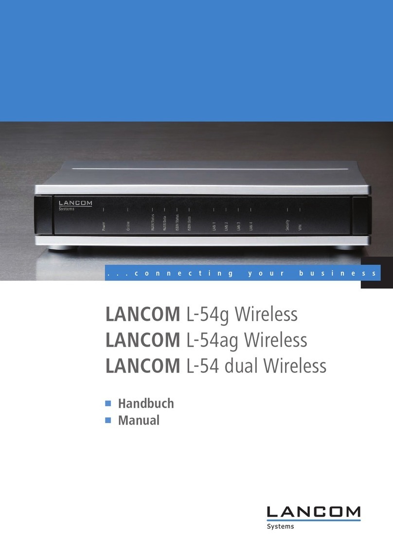
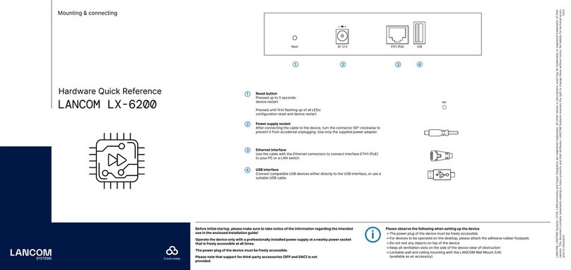
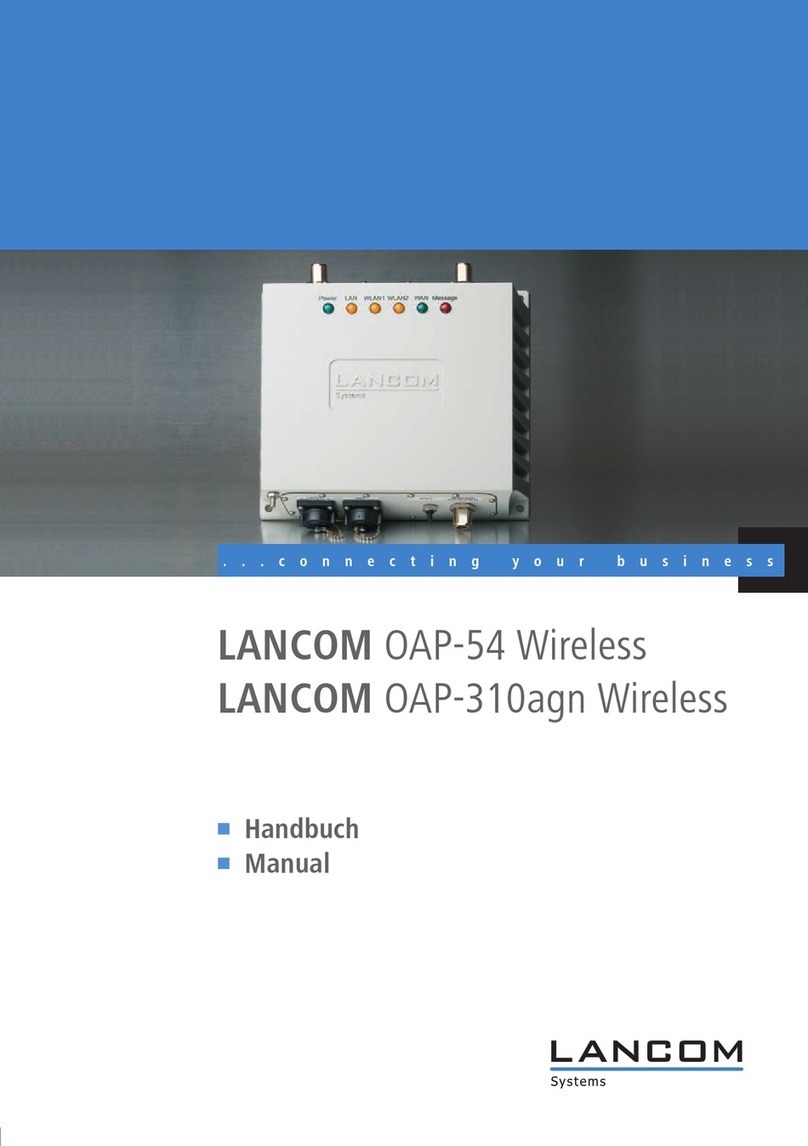
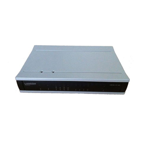
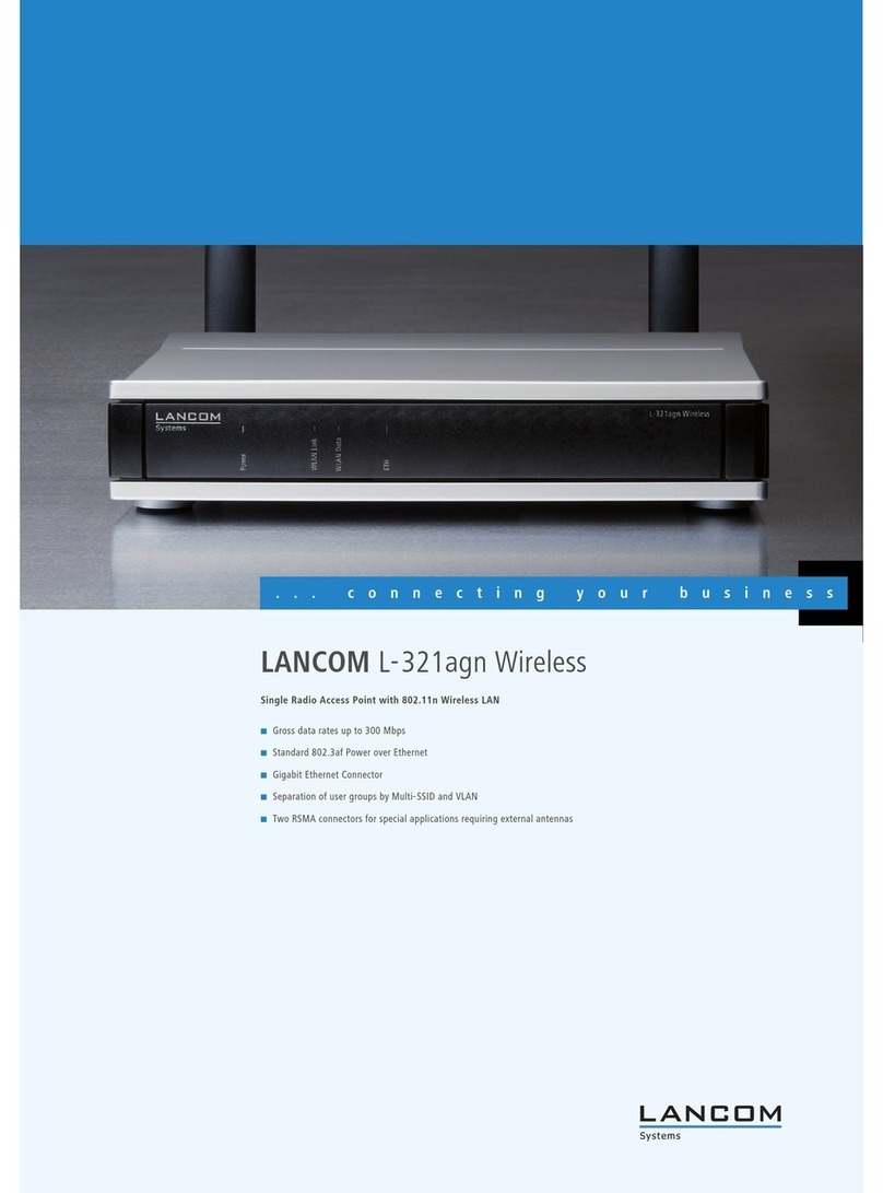
Lancom L-54ag Wireless User manual

LANCOM L- 54ag Wireless
LANCOM L- 54g Wireless
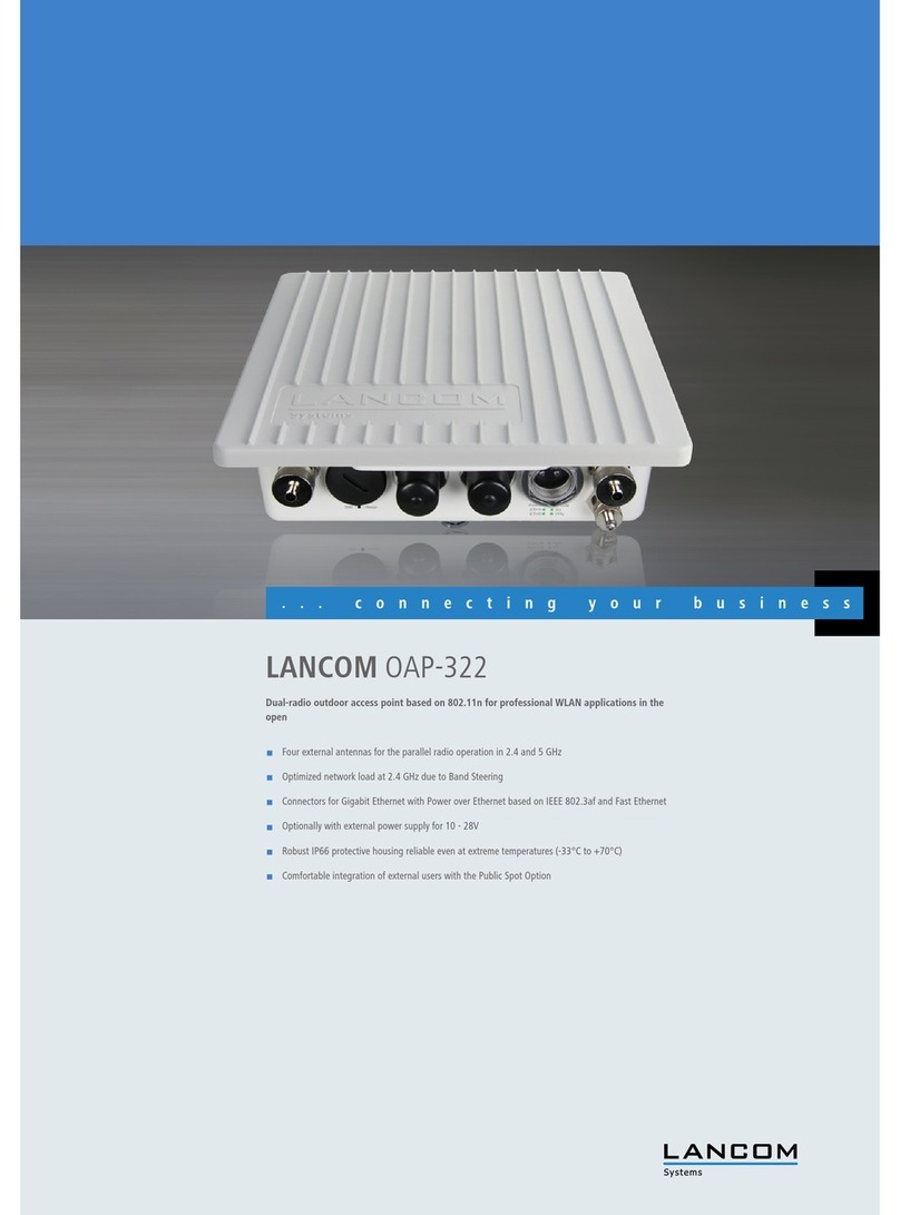
LANCOM IAP- 54 Wireless

© 2004 LANCOM Systems GmbH, Wuerselen (Germany). All rights reserved.
While the information in this manual has been compiled with great care, it may not be deemed an assurance of product
characteristics. LANCOM Systems shall be liable only to the degree specified in the terms of sale and delivery.
The reproduction and distribution of the documentation and software included with this product is subject to written per-
mission by LANCOM Systems. We reserve the right to make any alterations that arise as the result of technical develop-
ment.
Trademarks
Windows®, Windows XP®and Microsoft®are registered trademarks of Microsoft, Corp.
The LANCOM Systems logo and the name LANCOM are registered trademarks of LANCOM Systems GmbH. All other names
mentioned may be trademarks or registered trademarks of their respective owners.
Subject to change without notice. No liability for technical errors or omissions.
This product includes software developed by the OpenSSL Project for use in the OpenSSL Toolkit http://www.openssl.org/.
LANCOM Systems GmbH
Adenauerstr. 20/B2
52146 Wuerselen
Germany
www.lancom.de
Wuerselen, November 2004
11
02
75/11
0
4

LANCOM L- 54ag Wireless – LANCOM L- 54g Wireless – LANCOM IAP- 54 Wireless
Preface
3
EN
Preface
Thank you for placing your trust in this LANCOM product.
A LANCOM base station by LANCOM Systems
makes available numerous cen-
tral functions and services to the participants of wireless networks. The base
station convinces by a simple configuration and a reliable continious opera-
tion. With high-effective technologies, it ensures data security within the
whole wireless network.
Security settings
For a carefree use of your device, we recommend to carry out all security set-
tings (e.g. Firewall, encryption, access protection, charge lock), which are not
already activated at the time of purchase of your device. The LANconfig wizard
’Check Security Settings’ will support you accomplishing this. Further informa-
tion regarding this topic can be found in chapter ’Security settings’
→page 40.
We ask you additionally to inform you about technical developments and
actual hints to your product on our Web page www.lancom.de, and to down-
load new software versions if necessary.
User manual and reference manual
The documentation of your device consists of two parts: the user manual and
the reference manual.
You are now reading the user manual. It contains all information you need to
start your LANCOM 54 Wireless. It also contains the most important technical
specification for the device.
The reference manual can be found on the CD as an Acrobat (PDF) document.
It is designed as a supplement to the user manual and goes into detail on top-
ics that apply to a variety of devices. These include for example:
Systems design of the LCOS operating system
Configuration
Management
Diagnosis
Security
Routing and WAN functions
Firewall

LANCOM L- 54ag Wireless – LANCOM L- 54g Wireless – LANCOM IAP- 54 Wireless
Preface
4
EN
Quality of Service (QoS)
Virtual Private Networks (VPN)
Virtual Local Networks (VLAN)
Wireless networks (WLAN)
LANCAPI
Further server services (DHCP, DNS, charge management)
Model variants
This documentation is for users of LANCOM 54 Wireless base stations. The
base station LANCOM 54 Wireless is to choose from different models. These
are:
LANCOM L-54ag Wireless, complying to the 802.11g standard in the 2,4
GHz band, which is downward-compatible to 802.11b devices.
LANCOM L-54g Wireless operates alternatively either in 802.11g mode in
the 2,4 GHz band, or in 802.11a mode in the 5 GHz band as well.
A LANCOM IAP- 54 Wireless also operates like a LANCOM L-54ag Wireless
either according to the 802.11g standard with 2.4 GHz or according to the
802.11a standard in at 5 GHz. It is additionally equipped with a special-
ized housing (IP50) for use in industrial environments such as in ware-
houses or production facilities.
Model
restriction
The sections of the documentation that refer only to a range of models are
marked either in the corresponding text itself or with appropriate comments
placed beside the text.
In the other parts of the documentation, all described models have been clas-
sified under the general term LANCOM 54 Wireless.
This documentation was compiled …
...by several members of our staff from a variety of departments in order to
ensure you the best possible support when using your LANCOM product.
In case you encounter any errors, or just want to issue critics or enhance-
ments, please do not hesitate to send an email directly to:
Our online services ( www.lancom.de) are available to you around the
clock should you have any queries regarding the topics discussed in
this manual or require any further support. In addition support from
LANCOM L- 54ag Wireless – LANCOM L- 54g Wireless – LANCOM IAP- 54 Wireless
Preface
5
EN
LANCOM Systems is also available to you. Telephone numbers and
contact information for LANCOM Systems support can be found on a
separate insert, or at the LANCOM Systems website.
Notes symbols
Very important instructions. If not followed, damage may result.
Important instruction that should be followed.
Additional instructions which can be helpful, but are not
required.

LANCOM L- 54ag Wireless – LANCOM L- 54g Wireless – LANCOM IAP- 54 Wireless
Contents
6
EN
Contents
1 Introduction 8
1.1 What is a Wireless LAN? 8
1.1.1 Which hardware to use? 8
1.1.2 Operation modes of Wireless LANs and base stations 8
1.2 What can your LANCOM 54 Wireless do? 9
2 Installation 11
2.1 Package contents 11
2.2 System preconditions 11
2.3 Introducing the LANCOM 54 Wireless 12
2.3.1 Status displays 12
2.3.2 The connectors 16
2.4 Hardware installation 19
2.4.1 LANCOM L-54g Wireless, LANCOM L-54ag Wireless 19
2.4.2 LANCOM IAP-54 Wireless 21
2.5 Software installation 23
2.5.1 Starting LANCOM setup 24
2.5.2 Which software should you install? 24
3 Basic configuration 25
3.1 Which information is necessary? 25
3.1.1 TCP/IP settings 25
3.1.2 Configuration protection 27
3.1.3 Settings for the Wireless LAN 27
3.1.4 Connect charge protection 28
3.2 Instructions for LANconfig 28
3.3 Instructions for WEBconfig 30
3.4 TCP/IP settings to workstation PCs 34
4 Setting up Internet access 36
4.1 What does a router do? 36
4.2 Setting up the Internet access with DSLoL 37
4.3 Instructions for LANconfig 38
4.4 Instructions for WEBconfig 38

LANCOM L- 54ag Wireless – LANCOM L- 54g Wireless – LANCOM IAP- 54 Wireless
Contents
7
EN
5 Security settings 40
5.1 Security for the Wireless LAN 40
5.1.1 Closed network 40
5.1.2 Access control via MAC address 41
5.1.3 LANCOM Enhanced Passphrase Security 41
5.1.4 Encryption of the data transfer 41
5.1.5 802.1x / EAP 43
5.1.6 IPSec over WLAN 44
5.1.7 Tips for handling keys 44
5.2 The security settings wizard 44
5.2.1 Wizard for LANconfig 45
5.2.2 Wizard for WEBconfig 46
5.3 The firewall wizard 46
5.3.1 Wizard for LANconfig 46
5.3.2 Configuration under WEBconfig 47
5.4 The security checklist 47
6 Options and accessories 51
6.1 Optional AirLancer Extender antennas 51
6.2 LANCOM Public Spot Option 52
7 Troubleshooting 54
7.1 No WAN connection is established 54
7.2 DSL data transfer is slow 54
7.3 Unwanted connections under Windows XP 55
8 Appendix 56
8.1 Performance data and specifications 56
8.2 Radio channels 58
8.2.1 Radio channels in the 2,4 GHz frequency band 58
8.2.2 Radio channels in the 5 GHz frequency band 59
8.2.3 Radio channels and frequency ranges for Indoor
and Outdoor operating 61
8.3 Contact assignment 64
8.3.1 LAN interface 10/100base-TX 64
8.3.2 Configuration interface (Outband) 64
8.4 Declaration of conformity 65
9 Index 66

LANCOM L- 54ag Wireless – LANCOM L- 54g Wireless – LANCOM IAP- 54 Wireless
Chapter 1: Introduction
8
EN
1Introduction
1.1 What is a Wireless LAN?
The following sections describe the functionality of wireless networks
in general. The functions supported by your device are listed in the
table ’What can your LANCOM 54 Wireless do?’ →page 9.
A Wireless LAN connects single terminals (e.g. PCs or notebooks) to a local
network (also LAN – Local Area Network). In contrast to a conventional LAN,
communication takes place via radio links rather than via network cables. This
is the reason why a Wireless LAN is also called a Wireless Local Area Network
(WLAN).
All functions of a cable-bound network are also available in a Wireless LAN:
access to files, servers, printers etc. is as possible as the connection of individ-
ual stations to an internal mail system or to the Internet access.
The advantages of Wireless LANs are obvious: notebooks and PCs can be set
up just where they are needed. Due to Wireless LANs, problems with missing
connections or structural alterations belong to the past.
1.1.1 Which hardware to use?
Each station of the Wireless LAN needs access to the Wireless LAN in the form
of a wireless interface. Devices which have no built-in wireless interface can
be upgraded with a supplement card or an adapter.
LANCOM Systems offers wireless adapters by its AirLancer product
line. An AirLancer wireless adapter enables a device (e.g. PC or note-
book) for access to the Wireless LAN.
1.1.2 Operation modes of Wireless LANs and base stations
Wireless LAN technology and base stations in Wireless LANs are used in the
following operation modes:
Simple direct connections between terminals without base station (ad-
hoc mode)
Larger Wireless LANs, connection to LANs with one or more base stations
(infrastructure network)

LANCOM L- 54ag Wireless – LANCOM L- 54g Wireless – LANCOM IAP- 54 Wireless
Chapter 1: Introduction
9
EN
Passing-through of VPN-encrypted connections with VPN pass-through
Setting-up of an Internet access
Connecting two LANs via a direct radio link (point-to-point mode)
Connecting of devices with Ethernet interface via base stations (client
mode)
Extending an existing Ethernet network with WLAN (bridge mode)
In this chapter we will show you briefly the technology of wireless networks.
In addition, we give you an overview of the various applications, functions
and abilities of your base station.
1.2 What can your LANCOM 54 Wireless do?
The following list shows you properties and functions of your device.
LANCOM L-54ag
Wireless
LANCOM L-54g
Wireless
LANCOM IAP-54
Wireless
Wireless LAN
Wireless transmission by IEEE 802.11g and
IEEE 802.11b
Wireless transmission by IEEE 802.11a
Turbo Mode
Super AG
Multi SSID
Roaming function
802.11i / WPA
WEP encryption
(to 128 Bit key length, WEP152)
IEEE 802.1x/EAP
MAC address filter (ACL)
Individual passphrases per MAC address
(LEPS)
Access to RADIUS server
Closed network function

LANCOM L- 54ag Wireless – LANCOM L- 54g Wireless – LANCOM IAP- 54 Wireless
Chapter 1: Introduction
10
EN
VLAN
Traffic lock function
Connection to the LAN
Fast-Ethernet-connection (10/100base-TX)
Power-over-Ethernet (PoE)
DHCP and DNS server
Internet access (IP router)
Connection for DSL modem (DSLoL)
Stateful Inspection Firewall
Firewall filter (address, port)
IP masquerading (NAT, PAT)
Quality of Service
Configuration and firmware
Configuration under Windows or with web
browser
Configuration wizards
FirmSafe
Serial interface for configuration via outband
cable
Optional software extensions
LANCOM Public Spot Option
Optional hardware extensions
AirLancer Extender antennas for extended
range
Housing
IP50-standard dust resistant metal housing
LANCOM L-54ag
Wireless
LANCOM L-54g
Wireless
LANCOM IAP-54
Wireless

LANCOM L- 54ag Wireless – LANCOM L- 54g Wireless – LANCOM IAP- 54 Wireless
Chapter 2: Installation
11
EN
2 Installation
This chapter will assist you to quickly install hardware and software. First,
check the package contents and system requirements. The device can be
installed and configured quickly and easily if all prerequisites are fulfilled.
2.1 Package contents
Please check the package contents for completeness before starting the
installation. In addition to the base station itself, the package should contain
the following accessories:
If anything is missing, please contact your retailer or the address stated on the
delivery slip of the unit.
2.2 System preconditions
Computers that connect to a LANCOM 54 Wireless must meet the following
minimum requirements:
LANCOM L-54ag
Wireless
LANCOM L-54g
Wireless
LANCOM IAP-54
Wireless
Power adapter
LAN connector cable (green plugs)
2 external single-band diversity antennas to
screw (2,4 GHz) with reverse SMA connection
2 external dual-band diversity antennas to
screw with reverse SMA connection
Serial configuration cable (black)
Mast-, wall- and rail mount accessories
1 Port PoE Power Injector
LANCOM-CD
Printed documentation

LANCOM L- 54ag Wireless – LANCOM L- 54g Wireless – LANCOM IAP- 54 Wireless
Chapter 2: Installation
12
EN
Operating system that supports TCP/IP, e.g. Windows XP, Windows Mil-
lennium Edition (Me), Windows 2000, Windows 98, Windows 95, Win-
dows NT, Linux, BSD Unix, Apple Mac OS, OS/2.
Wireless LAN adapter or access to the LAN (if the base station will be con-
nected to the LAN).
The LANtools also require a Windows operating system. A web
browser is required for access to WEBconfig.
2.3 Introducing the LANCOM 54 Wireless
This section introduces your device. We will give you an overview of all status
displays, connections and switches.
While the information in this section is useful for the installation of the
device, it is not absolutely essential. You may therefore skip this sec-
tion for the time being and go straight forward to the ’Hardware
installation’ →page 19.
2.3.1 Status displays
The front and the rear panels of the unit feature a series of LEDs that provide
information on the status of the device.
Front side
The LANCOM L-54g Wireless and LANCOM L-54ag Wireless have status dis-
plays on the front panel.
LANCOM L-54g Wire-
less, LANCOM L-54ag
Wireless
L-54 Wireless
Power
LAN Link
WLAN Link
WLAN Data
LAN Data

LANCOM L- 54ag Wireless – LANCOM L- 54g Wireless – LANCOM IAP- 54 Wireless
Chapter 2: Installation
13
EN
Top panel
Two additional LEDs on the top panel provide a convenient overview of the
most important status information, especially when the device is mounted
vertically.
LANCOM L-54g Wire-
less, LANCOM L-54ag
Wireless
LANCOM IAP-54
Wireless
Meanings of the LEDs
In the following sections we will use different terms to describe the behaviour
of the LEDs:
Blinking means, that the LED is switched on or off at regular intervals in
the respective indicated colour.
Flashing means, that the LED lights up very briefly in the respective col-
our and stay then clearly longer (approximately 10x longer) switched off.
Inverse flashing means the opposite. The LED lights permanently in the
respective colour and is only briefly interrupted.
Wireless Link
Power
Wireless Link
Power

LANCOM L- 54ag Wireless – LANCOM L- 54g Wireless – LANCOM IAP- 54 Wireless
Chapter 2: Installation
14
EN
Flickering means, that the LED is switched on and off in irregular inter-
vals.
Power This LED indicates that the device is operational. After the device has been
switched on, it will flash green for the duration of the self-test. After the self-
test, either an error is output by a flashing red light code or the device starts
and the LED remains lit green.
The power LED flashes red/green in alternation until a configuration
password has been specified. Without a configuration password, the
configuration data of the LANCOM is insecure. Under normal circum-
stances, you would assign a configuration password during the basic
configuration (instructions in the following chapter).
off Device off
green blinking Self-test when powering up
green Device ready for use
red/green blinking alternately Device insecure: configuration password not assigned
red blinking Time or connect-charge reached
Flashing Power LED but no connection?
There is no need to worry, if the Power LED of a LANCOM 54 Wireless
base station blinks red and you can no longer connect to the WAN.
This indicates that a preset time or connect-charge limit has been
reached. There are three methods available for unlocking:
Reset time limit.
Increase the limit that has been reached.
Completely deactivate the lock that has been triggered (set limit to '0').
If a time limit has been reached, you will be notified in LANmonitor. To reset the connect
charge protection, select Reset Charge and Time Limits in the context menu (right mouse
click). You can configure the connect charge settings in LANconfig under Management
Costs (you will only be able to access this configuration if ’Complete configuration display’
is selected under View Options… ).
You will find connect charge protection reset in WEBconfig and all parameters under Expert
Configuration Setup Charge-module.
Signal for a time limit
or connect charge limit
that has been reached
Power
LANCOM
Systems

LANCOM L- 54ag Wireless – LANCOM L- 54g Wireless – LANCOM IAP- 54 Wireless
Chapter 2: Installation
15
EN
WLAN Link Gives information about the Wireless LAN access of the internal wireless net-
work adapter of the base station.
The WLAN link display can assume three different conditions:
WLAN Data Gives information about data traffic in the Wireless LAN access.
The wireless link display can assume three different conditions:
LAN Link Condition of the LAN interface:
LAN Data Indicating data traffic on the LAN interface:
off no Wireless LAN adapter found
green Wireless LAN adapter ready for use
green blinking activity in the Wireless LAN (blink frequency indicates
the number of registered stations)
off no data traffic
green flickering data traffic
red flashing error in the Wireless LAN (e.g. sending error due to a
bad connection)
off no network device connected
green constantly on network device connected; transfer rate 100 Mbps
green regularly blinking connection establishing DSL over LAN
green on with short inter-
ruptions
DSL over LAN active (e.g. PPPoE via LAN access)
orange network device connected; transfer rate 100 Mbps (The
device cannot function as directed, since a 10 Mbps fast
connection is too slow for a 54 Mbps fast WLAN data
transmission in the LAN.)
off no data traffic
green flickering data traffic

LANCOM L- 54ag Wireless – LANCOM L- 54g Wireless – LANCOM IAP- 54 Wireless
Chapter 2: Installation
16
EN
2.3.2 The connectors
LANCOM L-54g Wireless, LANCOM L-54ag Wireless
With the LANCOM L-54g Wireless and LANCOM L-54ag Wireless the connec-
tions and switches of the base station are located on the back panel:
Connection for diversity antenna
Connection for the included power adapter
Node/hub switch – the sending and receiving lines of the LAN connector
() can be crossed within the device for a direct connection of a PC ('hub'
setting ). For connection to a hub or a switch, the switch should be
turned to 'node' setting (presetting). When using the operating mode
DSLoL, the switch must be turned to 'hub' for a directly connected
DSLmodem.
10/100base-Tx for the connection to the LAN. 10Mbp- or 100Mbp con-
nections are supported. The used transfer speed will automatically be
identified (autosensing).
The LAN connector of the LANCOM 54 Wireless base station supports the
Power-over-Ethernet standard (PoE). You find further information about
operating with PoE in the info box ’Power-over-Ethernet – elegant power
supply through the LAN wiring’ →page 17.
By activated DSLoL option, the LAN connector can also be used for con-
necting the LANCOM 54 Wireless base station to a broadband modem.
Connection for the serial configuration cable.
Reset switch – has two different functions depending on the length of
time that it is pressed:
Connector for main antenna (if necessary is here the spot to connect
AirLancer Extender
additional antennas)
Reset
AC 12 VAntenna Aux Antenna Main
LAN 10/100 MbHub
Node

LANCOM L- 54ag Wireless – LANCOM L- 54g Wireless – LANCOM IAP- 54 Wireless
Chapter 2: Installation
17
EN
Power-over-Ethernet – elegant power supply through the LAN wiring
LANCOM 54 Wireless base stations are prepared for the PoE power supply (Power-over-
Ethernet), corresponding to the 802.3af standard. PoE-enabled network devices can be com-
fortably supplied with power feeding through the LAN wiring. A separate external power sup-
ply for each base station is unnecessary, which reduces the installation complexity
considerably.
The power feeding into the LAN happens at a central position, either via a PoE power injector,
or via a so-called powerhub/powerswitch. For the LAN wiring is to note that all 8 wires must
be available by the cabling. PoE feeds the power over those four wires, which are normally
not used for data transfer.
The PoE supply works only in such network segments, in which exclusively PoE-capable
devices are operating. The protection of
network devices without PoE support is
guaranteed by an intelligent mechanism,
that tests the network segment for
devices without PoE support before start-
ing the PoE power feeding. The power is
only switched onto the segment, if no
devices without PoE support were
detected.
In a PoE installation use exclusively devices which correspond to the 802.3af
standard! For damages caused by inadmissible devices no warranty may be
claimed.
Power Injector
Hub/Switch
Installation of single devices
hub/switch
powerhub/powers
witch
LAN without power
LAN with power
Installation of several devices

LANCOM L- 54ag Wireless – LANCOM L- 54g Wireless – LANCOM IAP- 54 Wireless
Chapter 2: Installation
18
EN
LANCOM IAP-54 Wireless
With the LANCOM IAP-54 Wireless the access point’s connectors are located
on the base of the device:
Voltage connector for an external power supply as with the LANCOM 54
Wireless, protected by an IP50 sealing cap.
10/100Base-Tx for connection to the LAN. Supported are 10-Mbit or 100-
Mbit connections. The data transfer speed is recognized automatically
(autosensing).
The LANCOM IAP-54 Wireless LAN connector supports the Power-over-
Ethernet standard (PoE). Further information about PoE is available in the
info box ’Power-over-Ethernet – elegant power supply through the LAN
wiring’ →page 17.
By activated DSLoL option, the LAN connector can also be used for con-
necting the LANCOM 54 Wireless base station to a broadband modem.
Connection for the serial configuration cable and access to the reset but-
ton, protected by an IP50 sealing cap.
The function of the reset button
The reset button has two different functions depending on how long it is
pressed:
Restarting the device (soft reset) – push the button for less than five
seconds. The device will restart.
Resetting the configuration (hard reset) – push the button for more
than five seconds. All the device’s LEDs will light up green and stay on. As
soon as the reset switch is released, the device will restart with factory set-
tings.

LANCOM L- 54ag Wireless – LANCOM L- 54g Wireless – LANCOM IAP- 54 Wireless
Chapter 2: Installation
19
EN
Note that resetting the device leads to a loss on the WLAN encryption
settings within the device and that the default WEP key is active again
(’Standard WEP encryption’ →page 43).
2.4 Hardware installation
2.4.1 LANCOM L-54g Wireless, LANCOM L-54ag Wireless
The installation of the LANCOM 54 Wireless base station takes place in max-
imum five steps:
Antennas – Screw on the both included diversity antennas at the back of
the LANCOM 54 Wireless base station.
LAN – You can first connect the LANCOM 54 Wireless base station to your
LAN. For that purpose, plug the included network cable (green plugs) into
the LAN connector of the device and the other end into a free network
connecting socket of your local network (resp. into a free socket of a hub/
switch). In this case, the node/hub switch remains in the presetting
'node' ( ).
Alternatively, you can connect also a single PC. In this case, turn the node/
hub switch on 'hub' ( ).
The LAN connector identifies automatically the transfer rate (10/100
Mbps) of the connected network device (autosensing).
For information about the installation of PoE see the info box ’Power-
over-Ethernet – elegant power supply through the LAN wiring’
→page 17.
DSLoL – If you want to use your LANCOM 54 Wireless base station in
DSLoL mode, you can either connect the device directly to the DSL modem
(exclusive mode) or to a hub resp. switch of the cable-bound LAN (auto-
matic mode).
For the exclusive mode insert the included network cable (green plugs)
into the LAN connector of the device and the other end into the cor-
responding interface of the DSL modem. In this case, turn the node/hub
switch on 'hub' ( ).
For the automatic mode for simultaneous operating with LAN and DSLoL
insert the included network cable (green plugs) into the LAN connector of
the device and the other end into a free network connecting socket of

LANCOM L- 54ag Wireless – LANCOM L- 54g Wireless – LANCOM IAP- 54 Wireless
Chapter 2: Installation
20
EN
your local network (resp. into a free socket of a hub/switch). In this case,
the node/hub switch remains in the presetting 'node' ( ).
Connect to power – Connect socket of the unit to a power supply
using the included power adapter.
Use the supplied power supply unit only! Using an unsuitable power
supply unit may cause damage or injury.
LAN interface: exclusive or in parallel for DSLoL
There are two principle DSLoL operation modes available. Either use the exclusive mode when
connecting your LANCOM 54 Wireless directly to a DSL modem, or use the automatic mode
when connecting the LANCOM 54 Wireless to a hub or switch of a cable-bound LAN, and
connect this hub/switch again to the DSL modem. If the LANCOM 54 Wireless is broadcasted
as gateway via DHCP, computers in LAN
and WLAN can use the internet connec-
tion simultaneously via one physical
interface. Set the desired mode in
LANconfig in the Interface settings of the
DSLoL interface.
DSLoL supports all PPPoE-based Internet access lines, as well as those that are
supplied with a access router with multiple fixed IP addresses (such as many SDSL
business lines).
Note the setting of the node/hub switch
If the node/hub switch for your application is not in the right position, no correct connection
will be established between the LANCOM 54 Wireless base station and other devices of the
cable-bound LAN and/or a DSL modem.
The node/hub switch is always in position 'node', when the LANCOM 54 Wireless base station
is connected to a network. The setting 'hub' is needed, when the base station will be directly
connected to another device like a single PC or a DSL modem.
Reset
AC 12 VAntenna Aux Antenna Main
LAN 10/100 MbHub
Node
Node/hub switch
This manual suits for next models
2
Table of contents
Other Lancom Wireless Access Point manuals

Lancom
Lancom LX-6200 User manual

Lancom
Lancom L-54g Wireless User manual

Lancom
Lancom DSL Series User manual

Lancom
Lancom 821+ User manual

Lancom
Lancom OAP-54 User manual

Lancom
Lancom L-322agn User manual

Lancom
Lancom L-310agn Wireless User manual

Lancom
Lancom OAP-382 User manual

Lancom
Lancom L-305agn Wireless User manual

Lancom
Lancom LN-860 User manual