Glossary UH50 – FOR INTERNAL USE ONLY!
Landis+Gyr GmbH Glossary UH606-101b Page 4of 38
Details concerning calibration law
The software contains a part “requiring official calibration” and a part “not requiring official
calibration”.
Approval of the UH50 under calibation law refers to the part “requiring official calibration”. This
part contains the sensing and processing of the consumption values and must not be altered
without an additional endorsement in the approval. The part “not requiring offical calibration”
contains functions that are not relevant to billing.
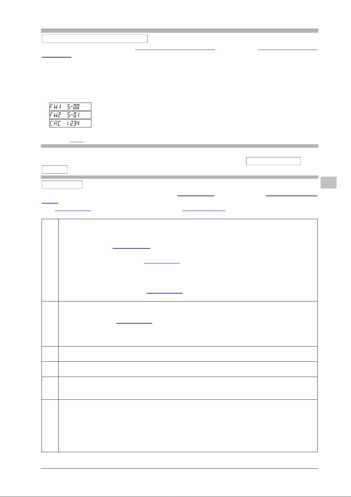
There are separate version numbers for the parts requiring and not requiring calibration. For the
part requiring calibration, there is a CRC checksum.
Firmware version of part requiring calibration (example)
Firmware version of part not requiring calibration (example)
CRC sum for part requiring calibration (example)
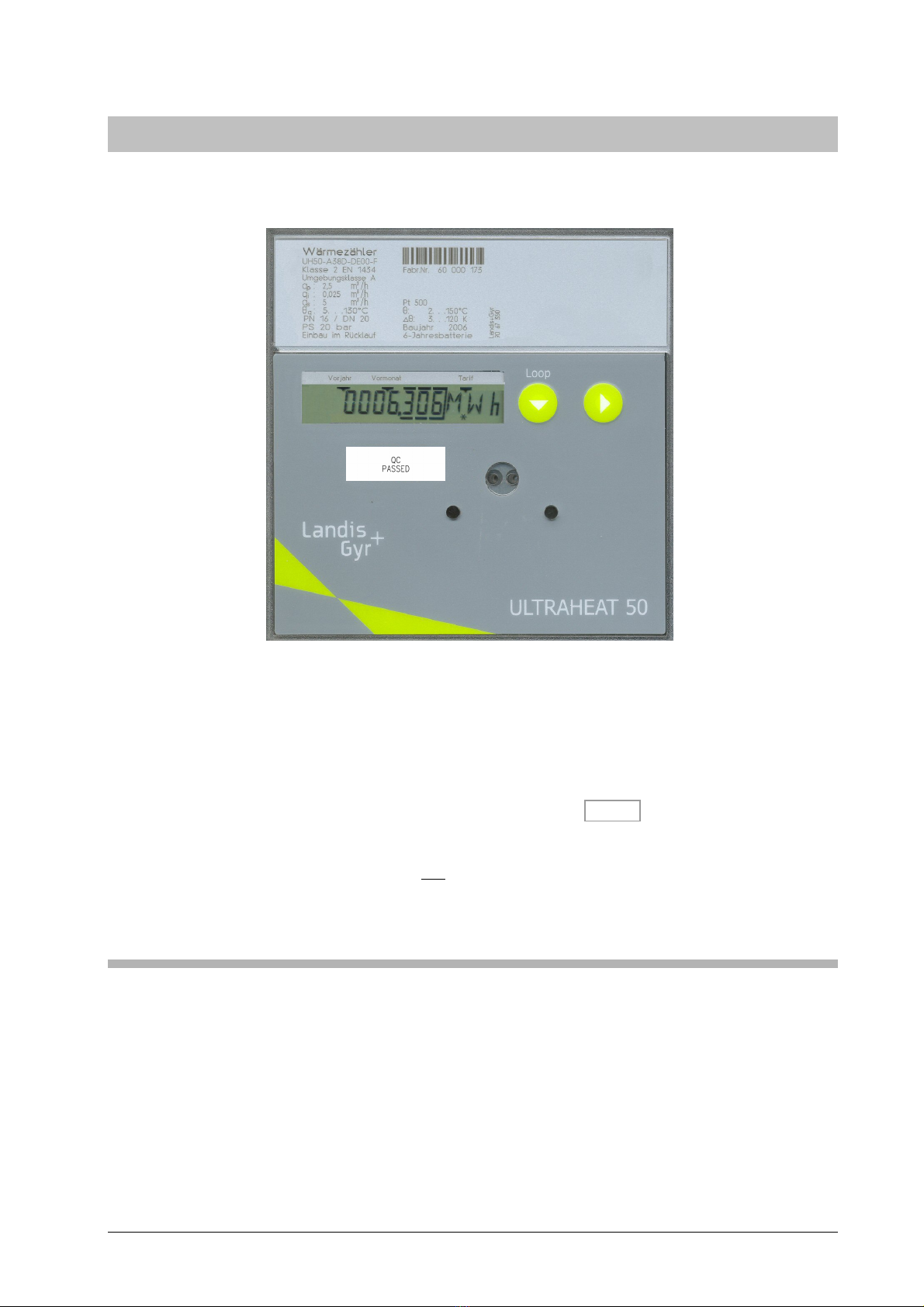
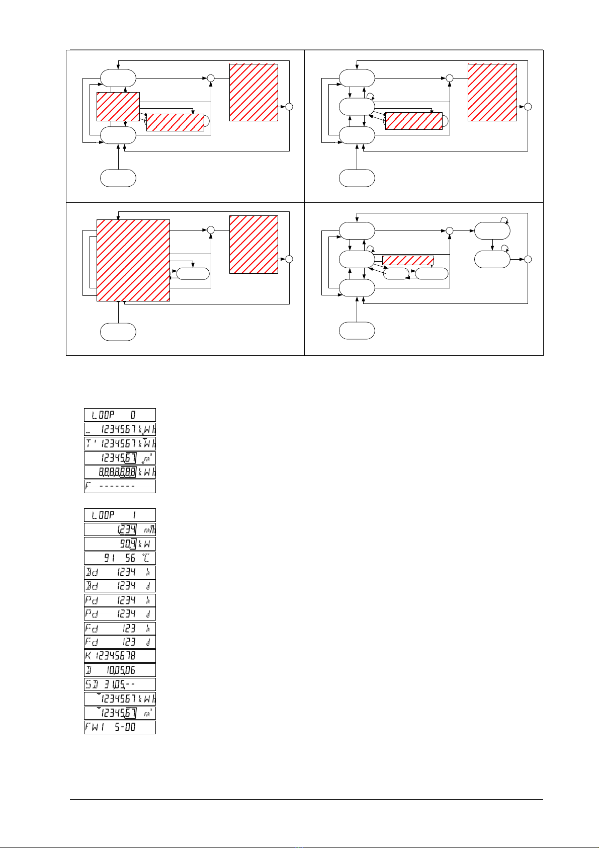
The values subject to calibration law (“calibrated values”) are marked by an additional symbol
(*) on the LCD.
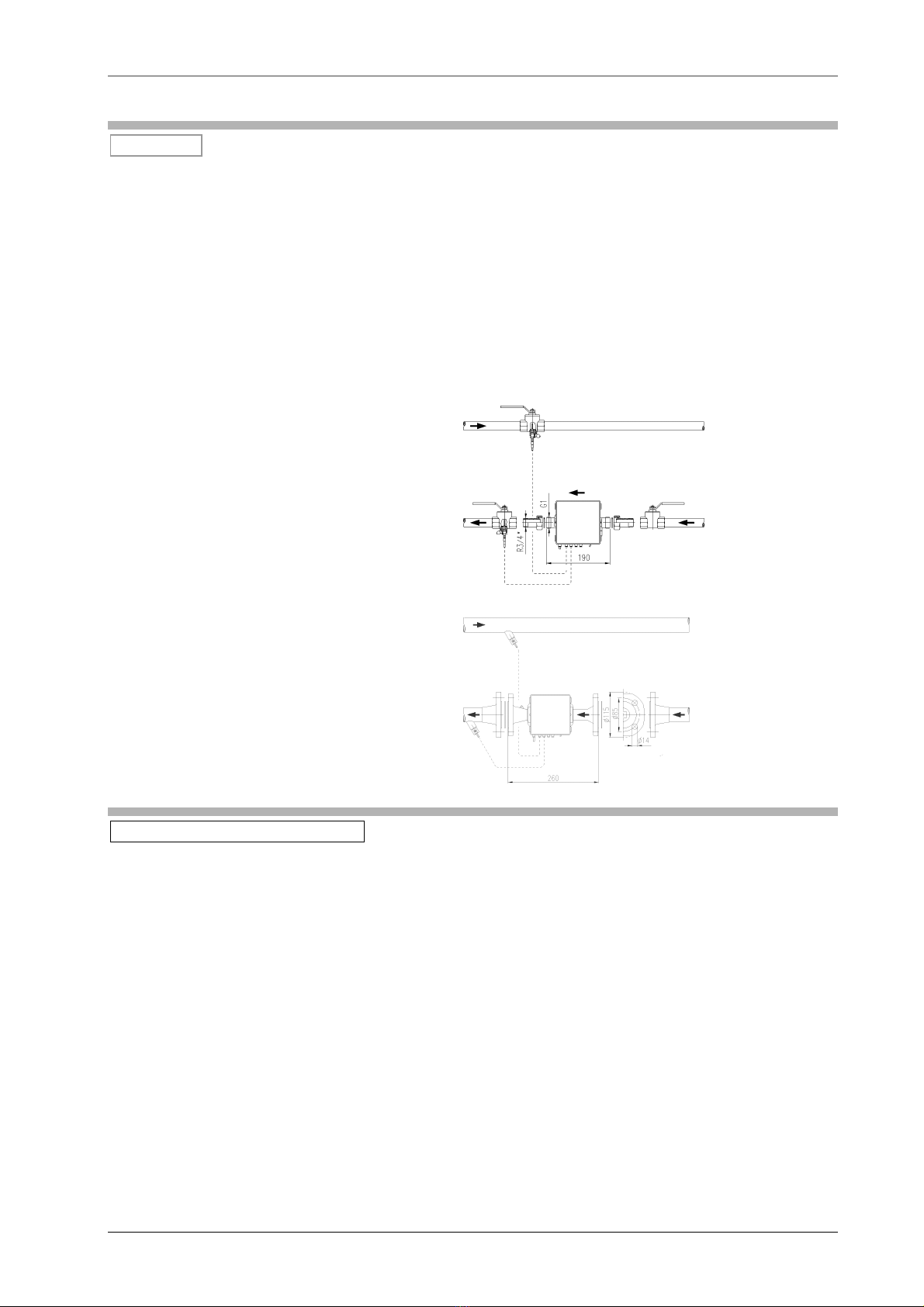
In Germany, small heat meters (up to including DN25) may be installed according to Directive
2004/22/EC Annex MI-004 Nos. 1.1 to 1.4 on new installation only with directy immersed
sensors.
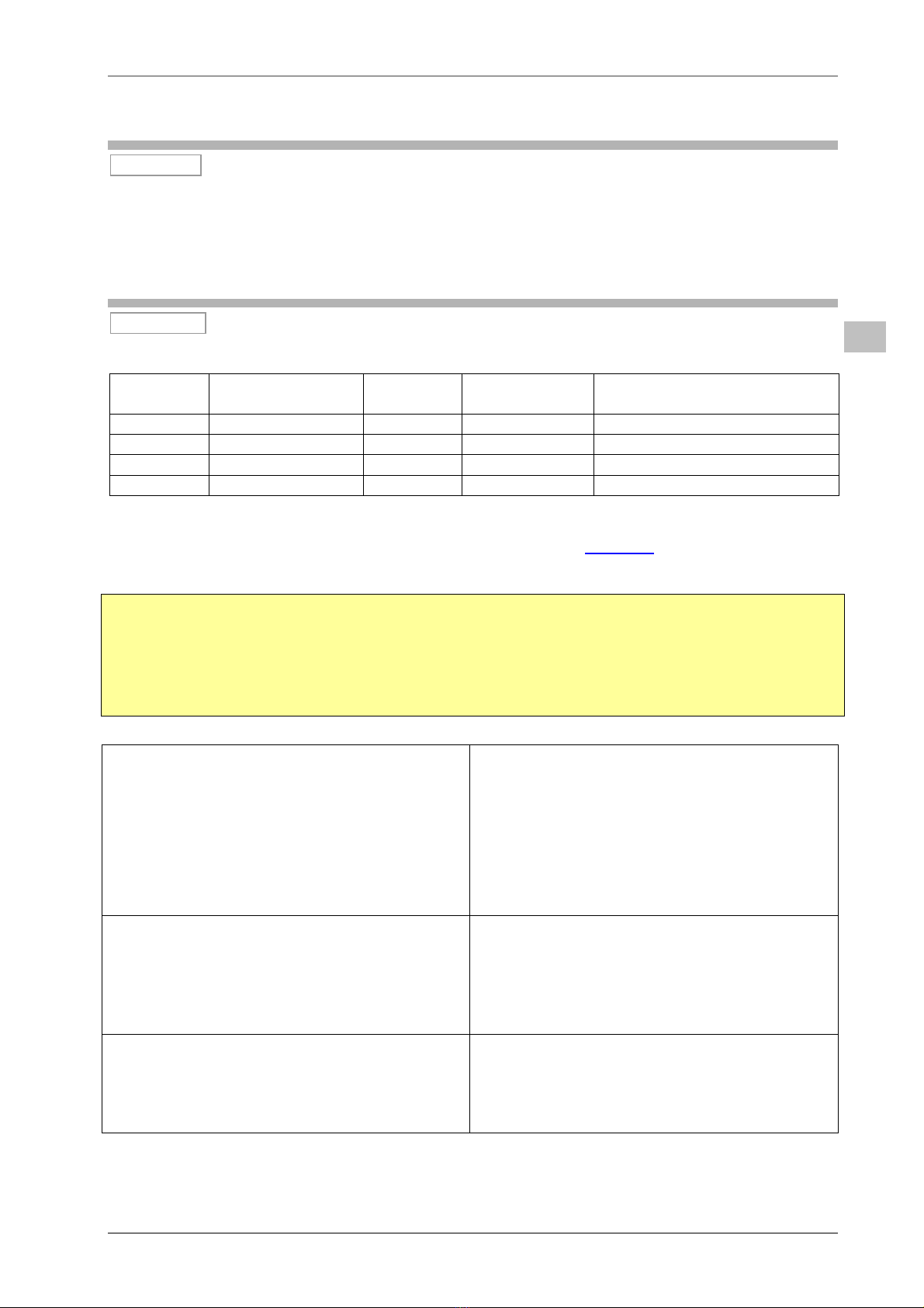
Error display
The error message F8 and the accumulated missing time can be reset in parameter setting
mode. This also deletes the flowrate measuring time!
The missing time is automatically reset after the calibration seal has been set (after a measured
flowrate of 10 liters).
F0 Air in the volume measuring part
- if measuring threshold < US signal < warning threshold, then:
“contamination message” with time stamp;
not treated as missing time (no F0 display on LCD)
- if US signal < measuring threshold, then:
“soft F0”; is evaluated as missing time;
output values for flowrate and power are not defined (no LCD values, no pulses,
“empty parentheses” in the telegram); no heat addition
- if “soft F0” is uninterrupted for longer than 8 hours, then:
“hard F0”, is evaluated as missing time;
the measurement timebase for the flowrate and temperature is increased to 100 s
F1
F2
Open-circuit flow sensor
Open-circuit return sensor
- is evaluated as missing time;
output values for flow/return temperature, temperature difference and power are not
defined (no LCD values, no pulses, “empty parentheses” in the telegram); no heat
addition
F3 Temperature electronics defective;
- Response as for F1/F2
F4 Supply voltage too low
- Response as for “hard F0”
F5
F6
Short-circuit flow sensor
Short-circuit return sensor
- Response as for F1/F2
F7 EEPROM defective
- No display while the error can be corrected via checksum
- Non-recoverable error in the part requiring calibration: no more measuring
- Recoverable error in the part requiring calibration: no F7 display on LCD, but error
output via data telegram
- Errors in the part not requiring calibration: data affected are not plausible and are
therefore not output
E