manuals.online logo
Brands
  1. Home
  2. •
  3. Brands
  4. •
  5. Landis+Gyr
  6. •
  7. Measuring Instrument
  8. •
  9. Landis+Gyr Ultracold T550 User manual

Landis+Gyr Ultracold T550 User manual

Ultraheat / Ultracold T550 (UC50…) Subject to change without prior notice Page 1 / 3
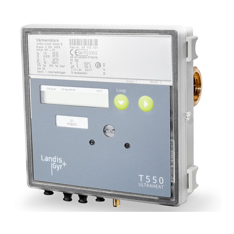
Calculator T550 Ultraheat®(UC50…)
Calculator T550 Ultracold®(UC50…)
Operating Instructions UC 309-101d
Issue: 29.10.2012
These Operating Instructions must be handed to the final user on start-up!
Note: In the following text, the term calculator covers
the heat meter calculator as well as the cold meter
calculator and the combined heat/cold meter calcula-
tor, if not mentioned otherwise.
General information
The T550 Ultraheat®(UC50…) calculator is de-
signed for heating and cooling applications. The
calculator forms the volumes from the pulses of the
flow sensor. The flow and return temperatures are
sensed using platinum resistors.
The volume of water and the temperature difference
between the flow and return are then calculated and
the product is summated.
The result is that the quantity of thermal energy con-
sumed is displayed in the units kWh / MWh or MJ /
GJ.

The mounting place and the pulse value
of flow sensor with pulse output must corre-
spond with the in the calculator set values
(see LOOP 2).
Technical data
Environment class A (EN 1434)
Mechanical class M1 *)
Electromagnetical class E1 *)
*) according 2004/22/EG directive
Ambient humidity < 93 % r. h. at 25°C
without condensation
Storage temperature - 20 to 60°C
Max. Height 2000 m above MSL
Ambient temperature 5 to 55°C
Housing degree of prot. IP 54 per EN 60529
Safety class
line 110 / 230 V AC II per EN 61558
line 24 V AC/DC III per EN 61558
Response threshold f. T0.2 K
Temperat. diff. T 3 K to 120 K
Temperat.meas. range 0...180°C
Sensors Type Pt500 or Pt100
per EN 60751
Temp. sensors length max. 10m
Battery 3,6V DC Lithium
Power supply 230/110V AC 50/60Hz
24V AC/DC 50/60Hz
Power input < 0,8W
Pulse input IB/IC per EN1434
Pulse length min. 10ms
Pulse frequency max 50Hz
Pulse wire length max. 20m (recommended)
Operating elements
Displays
The displays of the meter are arranged on several
levels (LOOPs).
Button 1 advances the display to the next loop. After
the last loop, the user loop (LOOP 0) appears again.
Button 2 displays the data of the selected loop. With-
in a loop, the button 1 is used to advance to the next
line of the display. After the last line of the display,
the first display line appears again.
The digits after the decimal point of displayed values
are indicated by a surrounding border.
Calibrated values can be recognized by the star
symbol shown in addition to the value.

Depending on how the unit is parameterized,
the number of items displayed and the data
shown may differ from this description. Cer-
tain button functions may also be disabled.
Service loop (selection)
Service loop 1
Service loop 2
…
…
User loop 0
User loop („LOOP 0“)
Head of the loop
Error message with error code numer 1)
Accumulated quantity of energy with tariff status
Tariff register 1,2,3 2)
Accumulated volume
Volume pulse input 1 3)
at 2 s interval with current volume
Volume pulse input 2 3)
at 2 s interval with current volume
Segment test
button 1
button 2
LCD display
3280 009 101 d
Ultraheat / Ultracold T550 (UC50…) Operating Instructions Page 2 / 3
Service loop 1 („LOOP 1“)
Head of the loop
Current flowrate
Current power
Current temperature „hot“, „cold“
at 2 s interval
Temperature difference
Volume pulse
Volume at energy calculation
Operating time
Error time
Property number, M-Bus secondary address
Date
Yearly set day (DD.MM)
Quantity of energy (previous year) on set day
at 2 s interval with date
Volume for previous year on set day
at 2 s interval with date
Tariff register 1,2,3, previous year on set day 2)
Firmware version
CRC Code
Service loop 2 („LOOP 2“)
The service loop 2, the installation details are dis-
played.
Head of the loop
Mounting place of the flow sensor cold
side or hot side
Pulse value

At a heat meter calculator or a combined
heat/cold meter calculator the mounting
place of the flow sensor cold side is
equivalent to return flow.
At a cold meter calculator the mounting
place of the flow sensor hot side is equiva-
lent to return flow.
Service loop 3 („LOOP 3“)
Service loop 3 shows the monthly values. Button 1
is used to select a month out of the previous months.
The data for that month are then opened with button
2. Each further press of button 2 shows the next
value for the selcted month.
After the last display, the previously selected set day
is displayed again. Pressing button 1 selects the next
set day.

If you want to exit and go directly to the
next loop, choose a monthly value by
pressing button 2 and then press button 1.
Head of the loop
Set day for june 2011
Quantity of energy on the set day
Tariff 1,2,3 on the set day 2)
Volume on the set day
Volume pulse input 1 3)
at 2 s interval with volume on the set day
Volume pulse input 2 3)
at 2 s interval with volume on the set day
Max. flowrate at period,
at 2 s interval with date stamp
Max. power at period,
at 2 s interval with date stamp
Max. temperatures „hot“ on the set day,
at 2 s interval with date stamp
Max. temperatures „cold“ at period,
at 2 s interval with date stamp
Error time count on the set day
Service loop 4 („LOOP 4“)
Service loop 4 shows the unit parameters.
Head of the loop
Current tariff 1,2,3 2)
at 2 s intervals with threshold value 1
Module 1: M-Bus module
M-Bus primary address 1
Module 2: pulse module; chan. 1 = energy;
Channel 2 = volume; at 2 s intervals
Significance for energy quantity pulses *)
Significance for volume pulses *)
Pulse duration in ms *)
1) Basic display if error existent
2) Visible if tariff is activated
3) Visible if a module with pulse input is installed
*) for „fast pulses“
Ultraheat / Ultracold T550 (UC50…) Operating Instructions Page 3 / 3
Previous year’s values
The electronic unit stores the meter readings for
quantity of energy, volume, the tariff register and
error time as well as the current maxima for flowrate,
power, temperature difference, flow temperature and
return temperature with their date stamps on a yearly
set day.
Monthly values
The electronic unit stores the calculator for quantity
of energy, volume, the tariff register and error time
as well as the monthly maxima for flowrate, power,
temperature difference, flow temperature and return
temperature with their date stamp for up to 60
months on the set day of each month.

The standard used is Cetral European
Time (CET). If daylight-saving time is
activated, storage will be performed
accordingly.
Error messages
The meter constantly performs self-diagnostics and
can display various error massages.
Error message F4 means the battery must be re-
placed.
Error message F1, F2 or F5, F6, F8 means that the
temperature sensor is defective. Massage F3, F7, F9
indicates a fault in the electronics. In all these cases,
please call service.
Functional details
If the response temperature threshols are exceeded
and the temperatur difference is positive, the quanti-
ty of thermal energy is summed. Power and tem-
perature difference are acquired with the correct
sign. If the response temperature threshold is not
reached, the value is preceded by a u. The current
temperatures are shown in separate lines with a
resolution of 0.1°C.
In the segment test, all segments of the display are
switched on for test purposes.
To calculate the maximum, the power and flowrate
are averaged over a measuring period of, for ex-
ample, 60 min. The maximum values from the av-
erage calculation are preceded by Ma. The maxi-
mum temperatures are preceded by MH resp. MC.
The 8-digit property number (also the secondary
address in M-Bus operation), can be set in parame-
ter setting mode. The unit number is assigned by
the manufacturer.
The operating time is counted from the first time the
power supply is connected. Error times are sum-
mated, if an error is pending that prevents the meter
from measuring.
The date is incremented daily.
The type of installed modules is displayed. If an M-
Bus module is installed, the primary and secondary
address awill be displayed on the following lines.
The number for the firmware version is assigned by
the manufacturer.
EU Declaration of conformity
Landis+Gyr herewith declares that the products of
type UC50 comply with the requirements of the fol-
lowing directives:
2004/22/ECMeasuring instruments directive *)
2004/108/EC Electromagnetic compatibility
2006/95/EC Low-voltage directive
1999/5/EC Directive on radio equipment and tele-
communication terminal equipment (R&TTE)
2002/95/EC Directive on the restriction of the use
of certain hazardous substances in electrical and
electronic equipment (RoHS)
*) for cold meter in Germany applies PTB TR K 7.2
This declaration and the corresponding documents are
lodged at Mr. Fuchs c/o Landis+Gyr under the number
CE UC50 003/10.12
EG type-examination certificate
DE-11-MI004-PTB035
EG design-examination certificate
DE-11-MI004-PTB036
Certificate of the approval of a quality management
system
DE-12-AQ-PTB006MID
Notified body: PTB Braunschweig and Berlin,
Germany; Nr. 0102
In Germany the cold meter is approved under the
number 22.75/11.04.
Further information
The electronic unit must only be cleaned on the
outside. Please use a soft, damp cloth to do this,
which can be dipped in a non-corrosive cleaning
agent.
User seals may only be removed by authorized
persons for service purposes and must be re-
placed afterwards.
Up-to-date versions of all instructions can be found
on our homepage www.landisgyr.com.
Landis+Gyr GmbH
Humboldtstr. 64
D-90459 Nuremberg
Germany

Other manuals for Ultracold T550

2

This manual suits for next models

1

Other Landis+Gyr Measuring Instrument manuals

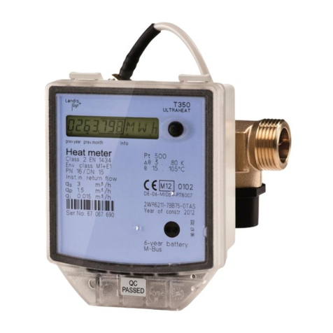
Landis+Gyr ULTRAHEAT T350 Series User manual

Landis+Gyr

Landis+Gyr ULTRAHEAT T350 Series User manual

Landis+Gyr FOCUS kWh User manual

Landis+Gyr

Landis+Gyr FOCUS kWh User manual

Landis+Gyr ULTRAHEAT T230 User manual

Landis+Gyr

Landis+Gyr ULTRAHEAT T230 User manual

Landis+Gyr T450 User manual

Landis+Gyr

Landis+Gyr T450 User manual

Landis+Gyr ULTRAHEAT XS User manual

Landis+Gyr

Landis+Gyr ULTRAHEAT XS User manual

Landis+Gyr ULTRAHEAT 50 Series User manual

Landis+Gyr

Landis+Gyr ULTRAHEAT 50 Series User manual

Landis+Gyr E450 User manual

Landis+Gyr

Landis+Gyr E450 User manual

Landis+Gyr E470 Series User manual

Landis+Gyr

Landis+Gyr E470 Series User manual

Landis+Gyr T450 User manual

Landis+Gyr

Landis+Gyr T450 User manual

Landis+Gyr ULTRAHEAT T350 Series User manual

Landis+Gyr

Landis+Gyr ULTRAHEAT T350 Series User manual

Landis+Gyr Ultracold T550 Parts list manual

Landis+Gyr

Landis+Gyr Ultracold T550 Parts list manual

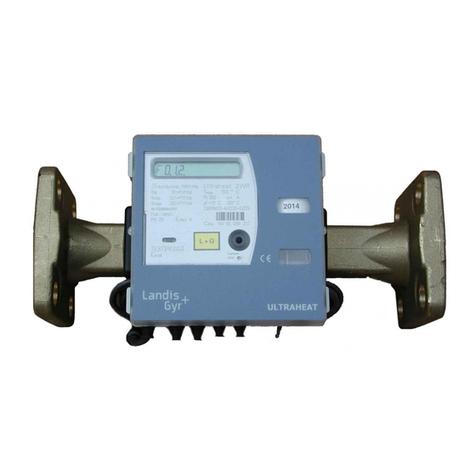
Landis+Gyr ULTRACOLD 2WR6 Series User manual

Landis+Gyr

Landis+Gyr ULTRACOLD 2WR6 Series User manual

Landis+Gyr 750 Guide

Landis+Gyr

Landis+Gyr 750 Guide

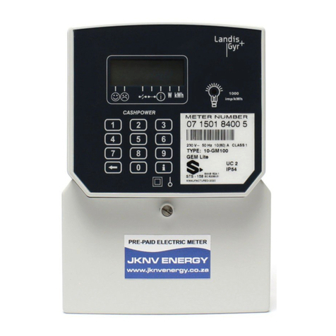
Landis+Gyr Cashpower Gem Lite User manual

Landis+Gyr

Landis+Gyr Cashpower Gem Lite User manual

Landis+Gyr E650 Series User manual

Landis+Gyr

Landis+Gyr E650 Series User manual

Landis+Gyr UH50 Series User manual

Landis+Gyr

Landis+Gyr UH50 Series User manual

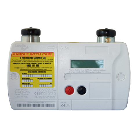
Landis+Gyr G130 User manual

Landis+Gyr

Landis+Gyr G130 User manual

Landis+Gyr E470 Series User manual

Landis+Gyr

Landis+Gyr E470 Series User manual

Landis+Gyr CASHPOWER SABRE MK 5 User manual

Landis+Gyr

Landis+Gyr CASHPOWER SABRE MK 5 User manual

Landis+Gyr E650 Series User manual

Landis+Gyr

Landis+Gyr E650 Series User manual

Landis+Gyr ZMQ202 User manual

Landis+Gyr

Landis+Gyr ZMQ202 User manual

Landis+Gyr E350 Series User manual

Landis+Gyr

Landis+Gyr E350 Series User manual

Landis+Gyr T450 Parts list manual

Landis+Gyr

Landis+Gyr T450 Parts list manual

Landis+Gyr Heat Meter Ultrasonic UH50 Quick guide

Landis+Gyr

Landis+Gyr Heat Meter Ultrasonic UH50 Quick guide

Popular Measuring Instrument manuals by other brands

SATO KEIRYOKI SK-RHG instruction manual

SATO KEIRYOKI

SATO KEIRYOKI SK-RHG instruction manual

Vega WEIGHTRAC 31 operating instructions

Vega

Vega WEIGHTRAC 31 operating instructions

FUJI CONTROLS IN-100 instruction manual

FUJI CONTROLS

FUJI CONTROLS IN-100 instruction manual

Piusi K24 Use, maintenance and installation manual

Piusi

Piusi K24 Use, maintenance and installation manual

Omron M22 datasheet

Omron

Omron M22 datasheet

Agilent Technologies FieldFox N9923A Quick reference guide

Agilent Technologies

Agilent Technologies FieldFox N9923A Quick reference guide

Sifos Technologies PowerSync PSA-3002-SA Technical reference manual

Sifos Technologies

Sifos Technologies PowerSync PSA-3002-SA Technical reference manual

WEHRLE WECOUNT-S operating instructions

WEHRLE

WEHRLE WECOUNT-S operating instructions

Polytron OME 200 operating manual

Polytron

Polytron OME 200 operating manual

SATO KEIRYOKI PC-7900GT instruction manual

SATO KEIRYOKI

SATO KEIRYOKI PC-7900GT instruction manual

Observator Instruments Analite NEP-5000 manual

Observator Instruments

Observator Instruments Analite NEP-5000 manual

Keysight Technologies N9040B Installation note

Keysight Technologies

Keysight Technologies N9040B Installation note

Leica RANGEMASTER CRF 1200 Specifications

Leica

Leica RANGEMASTER CRF 1200 Specifications

Würth WDM 30 operating instructions

Würth

Würth WDM 30 operating instructions

PCB Piezotronics 482C27 General operations manual

PCB Piezotronics

PCB Piezotronics 482C27 General operations manual

Sekonic FLASHMATE L-308X operating manual

Sekonic

Sekonic FLASHMATE L-308X operating manual

Apogee Instruments MQ-100 Series owner's manual

Apogee Instruments

Apogee Instruments MQ-100 Series owner's manual

F&F DMM-5T-3 user manual

F&F

F&F DMM-5T-3 user manual

manuals.online logo
manuals.online logoBrands
  • About & Mission
  • Contact us
  • Privacy Policy
  • Terms and Conditions

Copyright 2025 Manuals.Online. All Rights Reserved.