L&R Quantrex Q90 Owner's manual

2
Page
Safety Precautions .......................................................3
Chemicals Harmful to Your Ultrasonic Cleaner............4
What is Ultrasonic Cleaning? .......................................5
Ultrasonic Cleaner Specifications.................................6
Unpack, Set-up, and Start-Up ......................................9
Cleaning Methods ......................................................16
Popular Accessories...................................................18
Ultrasonic Cleaning Solutions ....................................19
Trouble Shooting ........................................................22
Foil Test......................................................................23
Service Center Locations ...........................................24
Table of Contents

3
Warning
FAILURE TO COMPLY WITH THESE WARNINGS AND PRECAUTIONS
WILL VOID YOUR WARRANTY.

4
Ferric Chloride
Ferrous Chloride
Ferris Sulfate
Fluoboric Acid
Fluorine
Hydrobromic Acid
Hyrdrochloric Acid
Hydrogen Peroxide
Hydrocyanic Acid
Hydrofluoric Acid
Hydrofluosilicic Acid
Iodoform
Mercuric Chloride
Muriatic Acid
Nitric Acid
Phosphoric (crude)
Sodium Hypochlorite
Potassium Chloride
Stannic Chloride
Stannous Chloride
Sulfur Chloride
Sulfuric Acid
Zinc Chloride
Chemicals Harmful To Your
Ultrasonic Cleaner
Acetophenone
Aluminum Chloride
Aluminum Fluoride
Aluminum Sulphate
Ammonium Bifluoride
Ammonium Chloride
Ammonium Hyroxide
Amyl Chloride
Antimony Trichloride
Aqua Regia
Benzethonium Chloride
Bromine
Calcium Bisulfate
Calcium Bisulfite
Calcium Hypochloride
Chloracetic Acid
Chloric Acid
Chlorine, Anhydrous
Chromic Acid
Chlorine Bleach
Citric Acid
Copper Chloride
Copper Fluoborate
Ethyl Chloride
The use of these chemicals will damage your machine
and void the warranty.

5
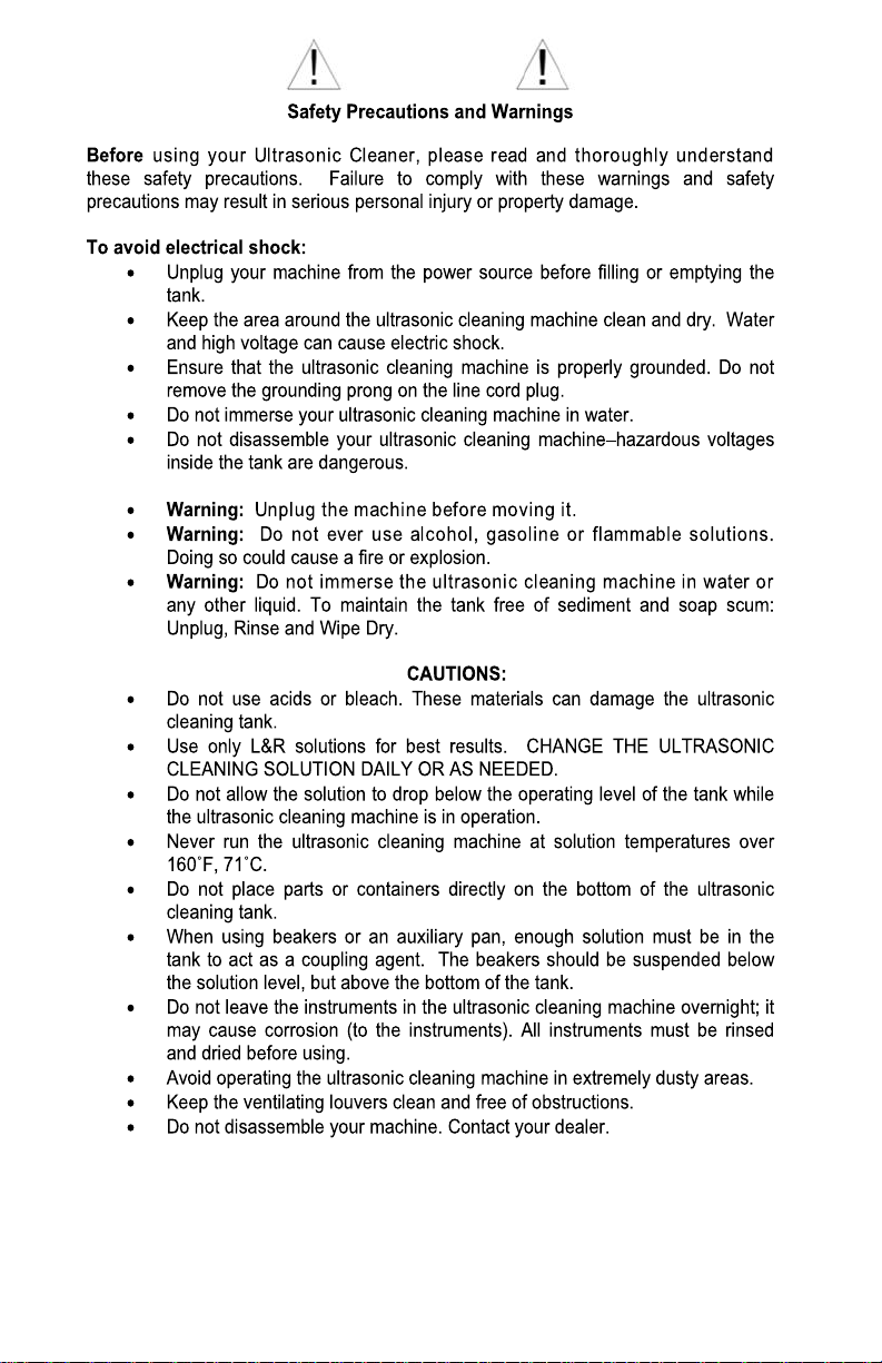
Sound waves are carried through the
solution in the tank and create a unique
vibrational pattern causing alternating
high and low pressures in the liquid.
During the low pressure stage, millions
of tiny bubbles form. This process is
called CAVTATION, meaning the
formation of cavities.
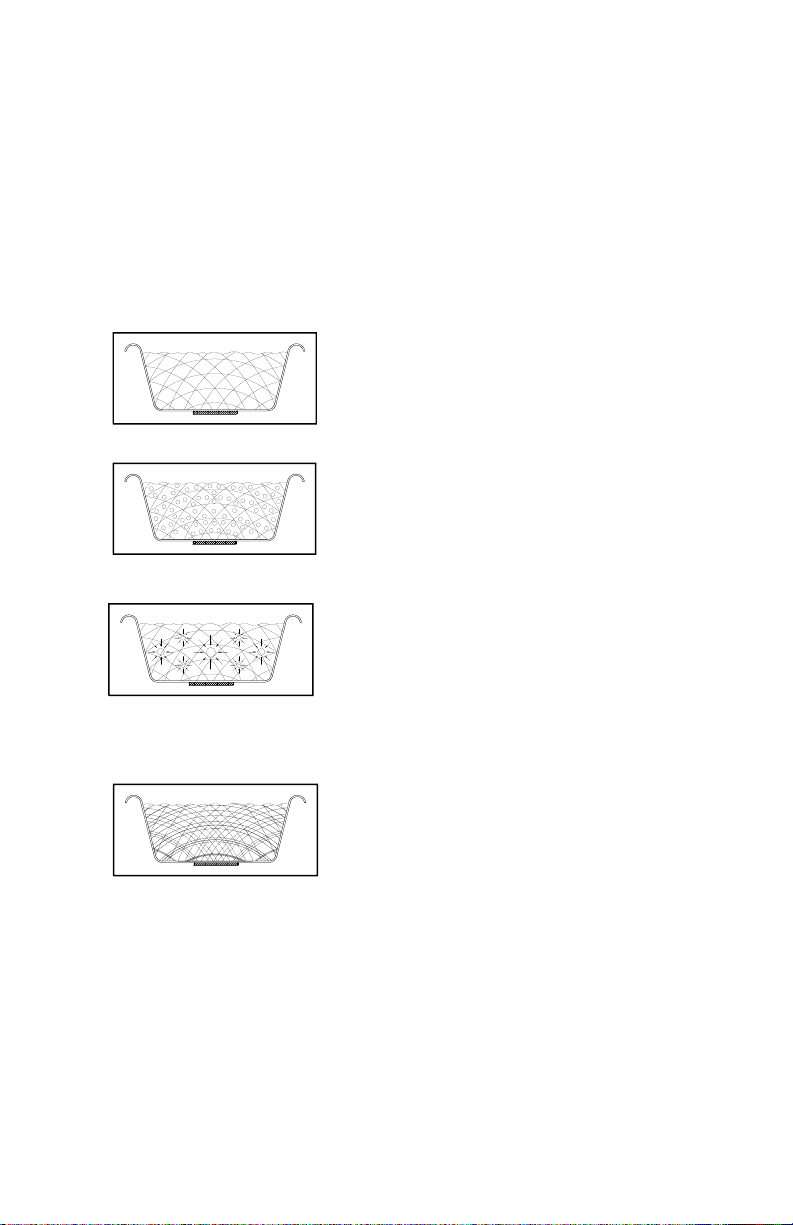
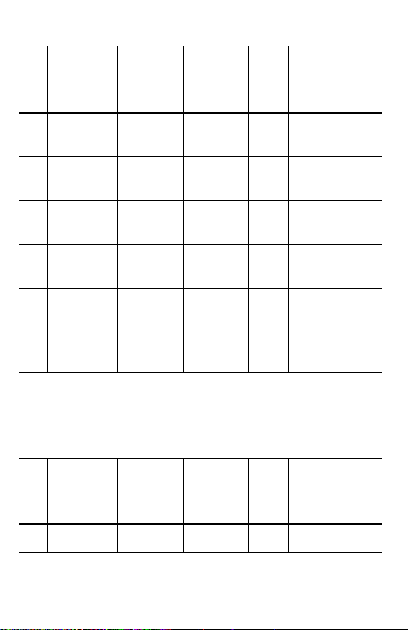
During the high pressure stage, the
bubbles collapse or implode, releasing
enormous amounts of energy. Working
in all directions, the bubbles attack
every surface and invade all recesses
and crevices, pulling debris off the
object being cleaned.
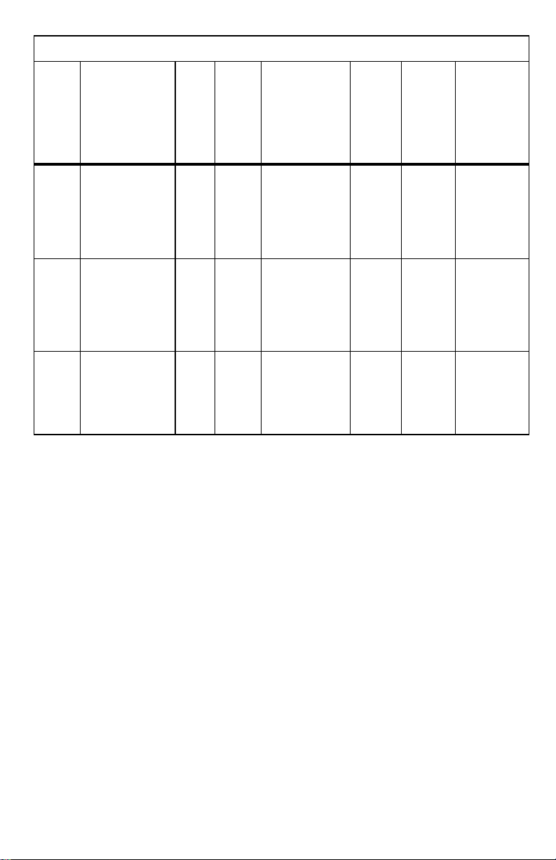
SweepZone Technology® enhances
the ultrasonic activity by automatically
changing frequencies, thus creating a
cleaning grid which literally sweeps
through the tank. A more uniform
cleaning pattern and significantly shorter
cleaning times result when “hot spots”
present in traditional ultrasonics are
eliminated.
Equally important to efficient cleaning is selecting a proper solution
for the cleaning task. See page 18 of this manual for cleaning
applications and solutions.
Congratulations on your purchase of an L&R Ultrasonic Cleaning
System. Your machine is part of a complete cleaning process which
is thoroughly described in this owner/operator manual.
What is Ultrasonic Cleaning?
Ultrasonic cleaning is created by sound waves that are transmitted
at frequencies beyond the range of human hearing. A generator
located within your system develops the high frequency power
which causes a transducer to radiate and produce the sound waves.

6
Quantrex® Models
Model Description
All Units Include
cover
Input
Power
Average
Watts
117
VAC
60 Hz
Output
frequency
Overall
Dimensions
Inches &
Centimeters
L x W x H
Shipping
Weight
Lbs.
& Kgs.
(Approx.)
Tank
Capacity
Gallons
& Liters
Tank Internal
Dimensions
Inches &
Centimeters
L x W x D
Q90
Timer standard 55
43 KHz
7.0 x 6.38 x 8.75 80.50 5.88 x 5.38 x 4.0
Heater optional 110 w/
heat 17.8 x 16.2 x 22.2 3.63 1.9 14.9 x 13.7 x 10.2
Q140
Timer, drain standard 95
43 KHz
10.25 x 6.5 x 8.25 10 0.85 9.38 x 5.38 x 4.0
Heater optional 150 w/
heat 26.0 x 16.5 x 21.0 4.3 3.2 23.8 x 13.7 x 10.2
Q210
Timer, drain standard 135
43 KHz
12.75 x 7.0 x 11.0 14 1.56 11.75 x 6.0 x 6.0
Heater optional 335 w/
heat 32.4 x 17.8 x 27.9 6.36 5.7 29.8 x 15.2 x 15.2
Q310
Timer, drain standard 320
43 KHz
16.5 x 10.0 x 12.13 26 3.25 15.5 x 9.0 x 6.0
Heater optional 520 w/
heat 41.9 x 25.4 x 30.8 11.7 12.3 39.4 x 22.9 x 15.2
Q360
Timer, drain standard 240
43 KHz
12.75 x 10.5 x 14.25 22 3.63 11.5 x 9.25 x 8.0
Heater optional 440 w/
heat 32.4 x 26.7 x 36.2 9.9 13.6 29.2 x 23.5 x 20.3
Q650
Timer, drain standard 415
43 KHz
21.75 x 13.75 x 12.7 33 6.30 19.75 x 11.75 x 6.5
Heater optional 815 w/
heat 55.2 x 34.93 x 32.3 15 24.6 50.2 x 29.8 x 16.5
PC3® Model
Model Description
All Units Include
cover
Input
Power
Average
Watts
117
VAC
60 Hz
Output
frequency
Overall
Dimensions
Inches &
Centimeters
L x W x H
Shipping
Weight
Lbs.
& Kgs.
(Approx.)
Tank
Capacity
Gallons
& Liters
Tank Internal
Dimensions
Inches &
Centimeters
L x W x D
PC3 Self-contained, high 22 55 KHz 5.38 x 4.13 x 5.0 40.14 4.75 x 3.38 x 2.63
performance unit 12.7 x 10.2 x 12.7 1.8 0.53 12.1 x 8.6 x 6.6

7
SweepZone®Models
Model Description
All Units Include
cover
Input
Power
Average
Watts
117
VAC
60 Hz
Output
nominal
frequency
sweep
range
Sweep
rate
Overall
Dimensions
Inches &
Centimeters
L x W x H
Shipping
Weight
Lbs.
& Kgs.
(Approx.)
Tank
Capacity
Gallons
& Liters
Tank Internal
Dimensions
Inches &
Centimeters
L x W x D
S200
Timer, drain standard 95 45 KHz 12.68 x 6.88 x 8.75 12 1.13 11.75 x 6 x 4
Heater optional 165 w/
heat +/– 2KHz 32.1 x 17.4 x 22.2 5.5 429.8 x15.2 x 10.2
3Hz
S310
Timer, drain standard 400 43 KHz 16.5 x 10 x 12 26 3.25 15.5 x 9 x 6
Heater optional 600 w/
heat +/–2KHz 41.9 x 25.4 x 30.5 11.7 12.3 39.4 x 22.9 x 15.2
83Hz
S1000
Timer, drain 500 44 KHz 19 x 17 x 20 101 10.00 16 x 14 x 10.5
standard 1445 w/
Heat +/–1.5KHz 48.3 x 43.2 x 50.8 45.6 44 40.6 x 36.6 x 26.7
83Hz

8
SweepZone® Recessed Units
Model Description
All Units Include
cover
Input
Power
Averag
e Watts
117
VAC
60 Hz
Output
nominal
frequency
sweep
range
Sweep
rate
Overall
Dimensions
Inches &
Centimeters
L x W x H
Shipping
Weight
Lbs.
& Kgs.
(Approx.)
Tank
Capacity
Gallons
& Liters
Tank Internal
Dimensions
Inches &
Centimeters
L x W x D
310R Timer, drain standard 400
43 KHz Generator 26 3.25 15.5 x 9 x 6
+/–2KHz 16.25 x 10.13 x 6.25 11.7 12.3 39.4 x 22.9 x 15.2
83Hz 41.3 x 25.7 x 15.9
360R Timer, drain standard 300
43 KHz Generator 22 3.63 11.5 x 9.25 x 8
+/–2KHz 16.25 x 10.13 x 6.25 9.9 13.6 29.2 x 23.5 x 20.3
83Hz 41.3 x 25.7 x 15.9
650R Timer, drain standard 500
43 KHz Generator 38 6.50 19.75 x 11.75 x 6.5
+/–2KHz 16.25 x 10.13 x 6.25 17.2 24.6 50.2 x 29.8 x 16.5
83Hz 41.3 x 25.7 x 15.9
ENVIRONMENTAL: For Indoor Use Only. Allow 2” or more behind unit for air flow.
Locate unit in a dry place, 0-35° C, RH 96% Non-Condensing non-corrosive
atmosphere below 2000M altitude. Position the unit to allow disconnecting the AC plug.
RECESSED SYSTEM: A Remote Timer is provided with the Recessed System. The Outlet on
the Remote Timer is for use with the Recessed System Remote Generator ONLY! This Outlet
is marked “ Remote Generator Only ”.

9
Unpack, Set-Up and Start-Up
Unpack
Remove your ultrasonic cleaner from its shipping container and
inspect it for any possible damage which may have occurred during
shipping. (Claims for shipping damage should be made immediately
against the carrier.)
Check the serial number of your machine with the serial number on
the shipping carton. If they are not the same, contact your dealer or
the factory.
Complete the warranty card and mail it to L&R Mfg. Co.
or visit www.LRultrasonics.com to register.
Set-Up
Table Top Machines
Select your desired location for the cleaner. It should be in close
proximity to a sink or waste lines to facilitate ease of draining. A drain
assembly, supplied with the cleaners having drains, will allow you to
place the unit on either side of the sink or to connect it directly into a
waste line. Provide at least two inches all around the machine to
allow for adequate cooling.
Directions for Attaching Pre-Assembled Drain Hose
for 140, 200 and 210 models
1. Open bag and remove pre-assembled drain hose.
2. Loosen large black nut on the elbow (drain fitting) at end of the
drain hose by turning 2 – 3 complete revolutions. (Be Careful:
Excessive turns will result in the black nut falling off and the elbow
coming apart.)
3. Turn the ultrasonic
machine so the back of
the unit is facing you.
Locate the metal drain
tube coming out of the
machine. Slide the elbow
(drain fitting) over the
metal drain tube until
elbow is almost flush with
back of machine. (Note:
Sliding the elbow will
require some force and it
is recommended to place
one hand on the front of
the machine for stability.)
4. To tighten elbow (drain fitting), turn the black nut counter-clockwise
while holding the elbow in place. (Be careful not to over-tighten the
black nut.)
5. Close drain hose by pressing down on pinch clamp until secure
(approximately 4 “clicks”).
6. Secure end of plastic tubing into clip at top of machine.

10
Attaching the Drain Assembly for 310 and 650 models
Pick up drain assembly supplied and loosen nut on
elbow.
Position machine so that you are facing the drain tube.
Carefully slide the assembly over the drain tube.
Adjust the position of the drain tube as desired. (Drain right, left or
down.)
Hand tighten nut. Do not over-tighten. If further
tightening is needed an adjustable or a 1 inch open-ended wrench is
recommended.
Recessed Machines
Installing the Tank in Your Countertop
Your recessed ultrasonic cleaner is designed to be a permanent
installation into a countertop in your office or shop. It is recommended
that the stainless steel mounting rim supplied with the cleaner be
installed between the rim of the tank and the countertop to ensure a
good, watertight seal at the countertop. A cable or cables (depending on
the model) will connect the tank to the generator.
1. Select your desired location for the tank on your countertop. Close
proximity to a sink is desirable for ease of drain connections.
a. Make sure there are no drawers below your selected position on the
countertop and that there are doors which allow easy access to the
drain valve on the tank.
b. If the cable(s) interconnecting the tank and generator can not be
routed behind the countertop, a separate hole will have to be drilled in
the countertop to accommodate them.
Vertical position - valve closed
Horizontal position - valve open
Valve Handle Drain Assembly
Drain Tube

11
2. Included with your recessed cleaner is a stainless steel
mounting rim. Use it as a template and trace the
required cut out on your countertop with a crayon or
china marker.
3. Drill a ½ inch hole anywhere within the section to be
cutout.
4. Using a sabre saw, carefully cut the tank shape out of
the countertop.
5. Clean away saw dust. Position the mounting rim over the
cut out and check fit. Adjust hole if required.
6. Remove rim. Carefully apply a bead of clear silicone (GE
732 or equivalent) ½ inch wide, ⅛ inch high around the
cut out.
7. Position mounting rim over cut out.
8. Carefully apply a bead of silicone ⅜ inch wide, ⅛ inch
high around the inside edge of the mounting rim.
9. Set the tank into the rim. Allow the silicone to squeeze
out. Wipe the excess silicone.
10. Allow the tank to set for at least eight hours without
being disturbed.
11. After the silicone has cured, carefully scrape any
excess silicone, being careful not to scratch the rim or
countertop.
Recessed rim option
Recessed rim installation is similar. For specific details
check instructions supplied with that option.
Connecting the Drain
Protruding through the bottom of the tank assembly on a
recessed machine is a drain valve and associated fittings
and a 36” length of tygon tubing.
Every recessed installation is unique because of different
counter sizes, access to waste lines, etc., and should be
done by a plumber or technician in accordance with local
plumbing codes.
Mounting rim
Bead of silicone about 1/2" (not to scale)

12
If a sink and sink drain are near the location the recessed
cleaner is to be installed, we recommend changing the
sink’s tailpiece to a “dishwasher tailpiece”. Then, using an
appropriate combination of adapters/fittings, the drain
tubing can be connected to the tailpiece. See sketch.
Interconnecting The Tank and Generator
S150R—Connect the coaxial cable from the tank into
the R.F. connector on the rear of the generator
(Turn Clockwise to lock connector).
S310R, S360R, S650R—Connect the coaxial cable
from the tank into the R.F. connector on the rear of the
generator (Turn Clockwise to lock connector) and the
thermo probe cable into the 3 pin connector on the rear
of the generator.
Connect the green/yellow wire from the tank to an
appropriate earth ground such as a cold water supply pipe
using a grounding clamp or similar approved grounding
device.
Do not attempt to connect or disconnect any cables with the
generator plugged in. Connect the generator plug last.

13
Start Up
STEP ACTION
1Select the proper L&R Cleaning Solution.
2Dilute with warm tap water as specified and
fill one half to two-thirds of the tank.
3
Add parts to be cleaned. Use a basket or
other accessory which keeps material off the
bottom of the tank. If necessary, add more
solution to bring the level to about 1 inch
from the top of the tank.
4
Plug the cleaner’s line cord into a grounded
outlet.
5
To activate your machine, simply set your
timer (on mechanical timers turn knob
clockwise) to the number of minutes desired
for cleaning. These self-timing units will
automatically shut themselves off at the end
of the cycle.
For recessed installations with an optional
remote timer… connect the machine’s power
cord to the outlet on the rear of the remote
timer and connect the remote timer’s power
cord to a grounded outlet. Set the machine’s
timer to the “HOLD” position. Then set the
timer on the remote to the number of
minutes desired for cleaning.
NOTE: If this is the first time you are running the cleaner or you
have changed the cleaning solution, you must degas the
solution. Fresh solutions contain many dissolved gasses which
reduce effective ultrasonic action. Although solutions will
naturally degas over time, operating the machine for five to ten
minutes before using it to clean will accelerate the degas
process.

14
Digital Timer
The L&R Digital timer controls the operation of the Ultrasonic cleaning machine
and its options. There are three sections of control; Main Power, Timer, Heat.
The Main power on / off switch: Located on the rear panel of the machine
near the line cord and fuse holder. This switch controls the main power to the
unit. When this switch is in the on position it is illuminated and the yellow
standby light, on the front panel, is lit (item 2).
Timer Section: The timer section controls the Ultrasonic operation of the
machine. There are five different selectable predefined timer settings (6, 12,
20, 30, 60 minutes). The timer set button (Item 1) is in the center of the time
selection indicator lights (Item 3) just below the yellow standby indicator light
(Item 2).
Pressing the timer button once, when the unit is in standby mode will
start the ultrasonic cleaner and select an operating time of 6 minutes. If
the timer button is pressed again a second time then the 12 minute indi-
cator will light and the unit will then run for 12 minutes and turn off when
done. If the timer button is pressed while the machine is operating the
next time interval is selected and the machine will continue to operate
until the end of this preset time. Pressing the timer button will increment
the time interval from 6 to 12 to 30 to 60 and then to Standby (off). The
time indicator light remains lit until the end of the cycle.
Optional Heater Section: The heater section has the heater push button
(Item 4) and a Red indicator light (Item 5). The light is active when the heater
circuit is energized. The heat remains on until the button is pressed again and
the indicator light goes off. If the unit has not had any buttons pressed for 2
hours the heat turns off as a safety precaution. Heat should not be left on unat-
tended. The operator should not rely on this automatic feature to turn the
heat function off automatically - this feature is for safety only.
The main power switch is intended to be turned off when the machine is
not in use. None of the digital timer functions will work if the main power switch
is in the off position.

15
Mechanical Timer
START-UP
1. To start your machine set your timer (item 1) to the pre-set
time (item 2) desired for ultrasonic cleaning. The machine will
automatically shut itself off at the end of the pre-set time.
2. Machines equipped with heat have a separate “On-Off” rocker
switch (item 3) located on the front panel. Pushing this switch
to the “On” position allows pre-heating of cleaning solution
prior to turning on the machine. The rocker switch is lit when
the heater is on and must be pushed to the “Off” position
when the heater is not in use.
3. The heater is designed to maintain the temperature of the
cleaning solution between 125°-150°F (52°– 65C°). When you
operate both the ultrasonics and heat simultaneously with the
tank covered for an extended period of time, the solution tem-
perature will rise above this level. At this point, the thermostat
will automatically shut the heater element off until the solution
drops below maximum heat level. The thermostat will be reac-
tivate as required. During this cycle, the heat indicator light will
remain lit. Because of the intense ultrasonic power dissipated
in the form of heat, the temperature of the solution may once
again rise above 150°F with the ultrasonics operating.
The heat rocker switch must always be turned off
manually. This switch does not turn off automatically.

16
Cleaning Methods
Direct Method
In this method, the part(s) to be cleaned are placed in your
accessory basket. The basket is then placed directly into the
main tank already containing the proper L&R cleaning
solution.
Cleaning times may vary depending on the amount and types
of contamination on the items. We suggest that a 3-5 minute
cycle be initiated and more time added if necessary.
Other applications of direct cleaning are pictured below:
A ring suspended directly into the tank.
Instrument cassettes, held in a cassette rack and placed
directly into the tank.
items in basket*
basket

17
Indirect Method
When a cleaning application necessitates a series of different
solutions, or when a specialized solution which is not to be
placed directly into the tank is to be used, the following
procedure is recommended.
Fill the stainless steel tank
approximately ⅔ full with a
proper L&R solution or carrier
bath.
Fill auxiliary pan or beaker (s)
with designated L&R cleaning
solution(s) to a level just above
the item(s) to be cleaned.
Place auxiliary pan into main
tank, resting it on its handles,
making sure that the bottom of
the auxiliary pan is below the
solution level in the main tank,
add water if necessary. This
insures proper sound wave
transference.
If a beaker or beakers are
used, place the beaker in an
L&R positioning cover using
the beaker band to adjust the
depth of the suspension so that
the beaker bottom is slightly
below the surface of the
solution in the main tank, but
off the bottom.
SOLUTION LEVEL
BEAKER
SOLUTION
LEVEL
POSITIONING
COVER
BEAKER
BAND
JUST ABOVE
ITEM
2/3

18
Popular Accessories
For Machine Type Solid Side
Draining Bas-
ket
Stainless
Steel Mesh
Basket
Auxiliary and
Soak Pan
PC3 N/A 13329 N/A
90 N/A 11086 11032
140, 150R, 2014 10632 11088 10634
200
full size 18666 19103 19366
¾ size 18670
210 15154 10140 11093
255 17732 18652 17801
280 15155 10141 10636
310, 310R full size 13518 N/A N/A
half size 18202 N/A N/A
360, 360R 18676 N/A 12267
650, 650R full size 17954 N/A 13102
half size 17953 17739 17740
1000 full size 19620 N/A N/A
half size 19355 N/A N/A
L&R supplies a full line of accessories for your Ultrasonic
Cleaning System. Consult your dealer for more information
or visit our web site at www.LRultrasonics.com.
Solid Side Basket Mesh Basket Auxiliary Pan

19
Ultrasonic Cleaning Solutions
L&R chemists have formulated a complete line of aqueous and non-aqueous
based solutions to compliment our ultrasonic cleaning systems. Listed below
are some of the common cleaning tasks and recommended L&R cleaning
solutions.
Solutions / General Cleaning Applications
L&R Solution P/C Qty Soils/Substrate
SF-1221 Gallon Light oils and greases. Safe on
metals, glass, plastic
SF-50 071 Gallon Carbonaceous soils, heavy oils,
greases
Hydrosonic
Concentrate 201 Gallon Fingerprints, oils, greases, lapping
and buffing compounds
Hydrosonic
Concentrate,
non-ammoniated
110 Gallon Same as above without ammonia
General Purpose
Cleaner,
ammoniated 226 Gallon Buffing compounds, tripoli and rouge
#112 Instrument
Cleaning
Solution, ammoniated 188 Gallon Gummed oils, greases, asphalt, tar,
carbonized residues
#222 Instrument
Cleaning Solution,
non-ammoniated
191 Gallon Same as above without ammoniate
odor
Instrument Rinsing
Solution 194 Gallon Rinse after cleaning with #112, #222

20
Watch/Jewelry Cleaning Applications
Jewelry Cleaner
Concentrate,
ammoniated
170
Gallon
Dirt, soap, light oil, fingerprints
Prep Clean, BCR 078 Gallon
Buffing compounds, light oils,
particulate soils
#111 Watch Cleaning
Solution, Ammoniated
112 Gallon Gummed oils, greases, sulfides
#566 Ultrasonic Watch
Cleaning Solution,
non-ammoniated
115 Gallon Same as above without ammonia
odor
#677 Ultrasonic Clock
Cleaning Solution,
non-ammoniated
135 Gallon Same as above
#3 Watch
Rinsing Solution
118 Gallon
Rinse after cleaning with #111,
#566, #677
Dental/Medical Cleaning Applications
Product Product
code size Description
UltraDose® Ultrasonic
Cleaning Solution UD012 24 x 1oz.
tubes Blood, debris, buffing compounds,
soils, oxides, rouges & tripoli
UltraDose® Germicidal
hospital grade Ultrasonic
Cleaner Concentrate UD036 16 oz. Disinfects instruments, appliance,
germicidal
General Purpose
Cleaner Concentrate,
non-ammoniated
228 Gallon Dried blood, debris, foreign
matter, buffing compounds
Tartar, Light Stain and
Perm. Cement Remover 232 Gallon Tartar & light stains, hard water
scale
Advanced Formula
Temporary Cement
Remover
293 Gallon Most temporary cements
Plaster and Stone
Remover 230 Gallon Plaster and stone
Evacuation Cleaner
Concentrate 107
Gallon Organic debris from evacuation
lines
Barrier Milk Concentrate 076 Gallon To protect instruments before
autoclave from corrosion
This manual suits for next models
12
Table of contents
Other L&R Cleaning Equipment manuals
Popular Cleaning Equipment manuals by other brands

OPTRONIC
OPTRONIC JetCam 40 Pro operating instructions

Homeright
Homeright Deck Pro StainStick With Gap Wheel instructions

General Pump
General Pump BIKLEENER 2100473 Operator's manual

Kwunphi
Kwunphi Kwun-E22H manual

Sealey
Sealey SM21.V4 instructions

Fantom Professional
Fantom Professional PROMAX 600 CM2 Assembly