manuals.online logo
Brands
  1. Home
  2. •
  3. Brands
  4. •
  5. Lanier R/C
  6. •
  7. Toy
  8. •
  9. Lanier R/C MARINER 40 MK II ARF User manual

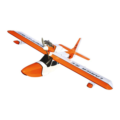
Lanier R/C MARINER 40 MK II ARF User manual

LANIER R/C’S
DOMINATOR 200
WARNING! THIS IS NOT A TOY!
THIS IS NOT A BEGINNERS AIRPLANE
This R/C kit an the mo el you will buil from it
is not a toy! It is capable of serious bo ily harm
an property amage. It is your responsibility,
an yours alone - to build this kit correctly, properly
install all R/C components and flying gear (engine,
tank, radio, pushrods, etc. and to test the model and
fly it only with experienced, competent help, using
commonsense and in accordance with all safety
standards as set forth in the Academy of Model
Aeronautics afety Code. It is suggested that you
join the AMA and become properly insured before
attempting to fly this model. If you are just starting
R/C modeling, consult your local hobby dealer or
write to the Academy of Model Aeronautics to find
an experienced instructor in your area.
Write to: Academy of Model Aeronautics, 5151
Memorial Dr. Muncie, IN 47302
BUILDING INSTRUCTIONS
Before starting to build this kit, we urge you to read
through these instructions while reviewing the plans.
They contain some important building sequences as
well as instructions and warnings concerning the
assembly and use of the model.
We expect that you have some building experience to
take on a built-up model. However, every minute
detail is not covered. This is not a basic trainer. The
plans and instructions together with the laser cut
parts, and the simplicity of this kit will allow you to
produce a first class DOMINATOR 200.
BUILDING SUPPLIES NEEDED
ingle edge razor blades
24” anding Tee w/ 80 grit paper
12” anding Tee w/200 grit paper
X-acto knife w/ #11 blade
Thin Zap CA
Medium Zap CA
low - Thick Zap CA
Zip Kicker
30 Minute Z-poxy
Laminating Z-poxy
Tee pins
Wax paper
Wire cutters
Pliers
Drill with bits: 1/16”, 1/8”, 5/32”, 3/16”
See the list at the en of the instruction book for a
list of a itional R/C equipment you will nee to
complete the DOMINATOR 200.
1. Lay wax paper out over the wing portion of the plans.
2. Cut both of the 1/8 x ¼ hardwood spars to 32” in
length.
3. Pin one spar in place over the plans, at the locations
indicated on the plans.
4. Using a sharp #11 blade, trim the ribs from the sheet.
5. Locate the ribs over the plans and use a square to hold
them at 90 degrees. Glue them in place with CA.
6. Glue the top spar in place.
7. Next cut the leading and trailing edge sheeting to size.
Trim (2) 1/16 x 3 x 36, first by cutting them to 32-
1/4”, then by making a few marks 1” from one long
edge, then trim along the marks using a straight edge.
8. Glue a 2” balsa LE sheet on the front of the wing,
aligning one edge on the center of the spar.
9. Glue a 1” balsa TE sheet on the rear of the wing,
aligning the sheet to the rear of the ribs.
10. Cut (2) 7” pieces from the remaining 1/16 x 3 x 36”
balsa sheet for the center sheeting. Trim one to fit on
the top of the wing, then glue in place.
11. Trim (8) pieces of 1/16 x ¼ balsa to length of the cap
strips on the wing, then glue in place.
12. Remove the pins, then turn the wing over.
13. hape the ½ x 1 x 1-1/2 balsa block to match the front
profile of the ribs, then glue in place between the two
center ribs.
14. Glue the LE and TE sheeting in place as was done on
the top of the wing. Be sure to keep the wing flat on
the board while gluing.
15. From the remaining 1/16 x 3” balsa, trim (11) ¾”
sheer webs.. Glue the webs in place at the rear of the
hardwood spars. You will have to trim the center web
to size to fit between the two center ribs.
16. Install the center sheeting and cap strips as was done
on the top of the wing.
17. Use a 24” sanding bar to sand the LE and TE sheeting
flat against the ribs.
18. Glue the 5/16 x ¼ balsa, with the 5/16 side against the
wing, to the LE and TE. Use the sanding bar to sand
the top of the TE flush with the sheeting. and the LE
to match the profile shown on the plans.
19. Using the plans as a guide, trim the 36” tapered
aileron stock to the sizes illustrated on the plans.
20. Mark the centerline of the TE out 6” from both
directions from the center of the wing. Using a piece
of brass tubing or the handle of a hobby knife, indent
the TE and the center piece of aileron stock to hold the
aileron torque rods ( ig #628). Notch the bottom of
the wing and aileron stock 3/16 in each direction from
the center of the wing to allow the torque rods to
move.
21. Carefully glue the brass portion of the torque rods in
place on the TE using a small amount of CA. Just as
carefully, using a small amount of CA, glue the center
section of the aileron stock in place.
22. Trim a piece of 2-1/2 nylon cloth (Goldberg #451) just
a little longer than the cord of the wing. pray the
cloth with a light coat of super 77 spray glue, then
place on the center of the wing. Rub out any bubbles
then glue with CA.
23. Fit the trimmed ailerons on the wing. and the
appropriate bevel on the front of the aileron,
depending weather you want to use ca or monokote
hinges. ee the plans for illustration. Drill a small
hole for the aileron torque rod.
Fuse
1. Locate the 2 fuse sides and lay them out so you have a
left and right side. and a slight taper on the inside
edge of the tail portion of the fuse sides.
2. Lay the two fuse sides together and align the tail edges
together, then hold together with a piece of masking
tape.
3. Insert formers F3 and F2 into the slots in the fuse and
doublers with the arrows facing the top of the fuse, but
o not glue yet.
4. Drill the firewall to match your chosen engine mount,
also drill holes for your fuel lines.
5. Align the fuse over the plans, then glue the firewall in
place with 30 minute z-poxy, keeping everything
aligned.
6. Now glue the formers in place with CA, and wick
some into the joint at the tail.
7. Test fit the 2 wing blocks on the fuse, and sand as
needed. Glue in place with 30 minute z-poxy. When
dry, cut (4) small pieces of ¼ triangle stock and glue
in place under the wing blocks.
8. Glue block B1 to the bottom of the fuse, aligning with
the firewall and the fuse sides.
9. Cut then glue (2) 1/4 sqr. Hardwood servo rails in the
holes provided in the rear of the fuse. You may need
to adjust one of the holes to fit your exact servos.
10. tarting at the rear of B1, sheet the bottom of the fuse
with cross grain 1/16 balsa.
Tail
1. For the standard tail, skip to step 4. For the v tail,
locate the horizontal stab (T1) and cut it in half along
the dotted line, using a razor saw. and the cut joint
to approximately 55 degrees on both halves.
2. Glue a horizontal stabilizer (hstab) tips (T2) to the
outside edges of the hstab, aligning them at the front
edges.
3. Glue the two tail pieces together at the center and form
a 110 degree joint. Reinforce the top and bottom of
the joint with a 1” wide strip of fiberglass (Goldberg
#451) and CA.
4. For the standard tail, glue the hstab tips (T2) to the
hstab (T1), aligning the front edges. Do the same for
the vertical stabilizer (vstab) (T3) and vstab tip (T4).
5. Use a pencil to mark a line 1/16” from each side of the
dotted line on the hstab.
6. Glue the vstab, centered on the hstab with CA. Brace
the vstab at 90 degrees until cured.
7. Remove the tail blocks from the rear of the fuse and
trial fit the tail in place. Align the tail parallel to the
centerline of the fuse. For the v tail, bevel the inside
edges to set the surfaces in place. Glue the tail in
place with CA.
8. Fill the tail joint in with balsa. For the v tail, use a
piece of the ¼” triangle stock on the top of the joint.
For the standard tail, use the balsa cut from the fuse
sides. Fill either tail flush with the top of the fuse
sides.
Final assembly
1. Align the wing on the fuse and measure that it is
square. Adjust so that measurements from the wing
tips to the point of the tail are equal. When all is
aligned, clamp in place.
2. Drill (4) 1/8” pilot holes through the wing into the ply
wing blocks. Remove the wing and thread the fuse
holes with a 10-32 tap. Drill the wing holes out with a
3/16” drill.
3. Remount the wing on the fuse using 10-32 bolts
(Dubro #164). Test fit, trim, then glue the 1/8” balsa
fuse cover on the rear of the fuse. Two are supplied,
one for the v tail and one for standard. Make sure you
leave a 1/32 to 1/16 gap from the te of the wing.
4. Test fit the fuse front block (B2) over the tank area of
the fuse. Trim the front edge even with the firewall.
DO NOT GLUE YET!
5. If you are using an engine with a throttle, install your
engine control rod ( ullivan #507) in the lower right
corner of the fuse, getting it as far down in the corner
as possible. It’s very important that you install the
control rod housing now, as you won’t be able to
install it after you install the tank.
6. Assemble the ullivan 1 oz round tank ( ullivan
#400) per the manufacturers instructions. lide a 6”
piece of fuel line (Dubro #222) through the hole in the
firewall, with the loose ends inside the fuse. lide the
fuel line on the brass lines for the tank, then safety
wire the lines on the tank. Carefully slide the tank in
place, while pulling the slack of the lines out of the
fuse. Be careful not to crimp the fuel lines.
7. Now glue the block (B2) in place, being cautious not
to glue the wing to the fuse or the block.
8. and the fuse sides square with each other, being
careful not to sand through the fiberglass on the nose.
Radius the corners of the fuse to a 1/8” radius, but
remember to leave the firewall square.
9. Trim and test fit the control surfaces, elevators (T5),
and rudder (T6) (if used). Bevel the front edges to a
“v” shape if using CA type hinges or a 45 degree
bevel if you are using monokote hinges.
10. If you are building the standard tail, bend the 1/16
wire to the shape shown on the plans, and notch the
elevator halves to fit the wire.
11. Now cover your plane with monokote or similar
plastic covering.
12. Install the radio components per the manufacturers
recommendations. For the ailerons, cut a small hole,
just big enough for your servo base to fit, then glue the
ply aileron mounting plates in place, as shown on the
plans. When dry, install your servo.
13. If using a throttle, install the throttle servo on the floor
of the fuse using 2 sided foam tape (Dubro #634).
14. Connect the aileron with (2) 2-56 control rods (Dubro
#172), z bends at the servo horn, and 2-56 clevis
( ullivan #525) with the connectors included with the
torque rods.
15. Connect the elevator and rudder servos to the tail with
(2) ullivan precision rods ( ullivan #586), 2-56
clevis, and 1/2a control horns (Dubro #107). You
may want to trim the horns shorter for added
clearance.
16. Install your Hayes engine mount (Hayes #059) using
(4) # 2 screws (Dubro #381). If you use the hole in
the firewall to route your fuel tubing, use a razor saw
to cut out approximately ½” of the mount to allow the
fuel line to pass behind the engine.
17. et the control throws initially to +/- 1/4” for all
surfaces. After flight testing, adjust as needed.
18. et the cg from 1-5/8” TO 2” from the leading edge.
Keep the cg to the front for the initial flights, then
adjust as needed.
19. Double check that all bolts are tight and use loctite
where needed, and double check the cg, then charge
your planes batteries.
20. Enjoy the plane and win some races.
ADDITIONAL EQUIPMENT NEEDED TO
COMPLETE YOUR DOMINATOR 200
General
.049-.061 ize two stroke R/C engine
Minimum of 2 channel radio set required
(2-4) Micro servos w/250-350 mah battery
1 Roll of Top Flight Monokote covering
ullivan -1 oz round tank #400
30 minute Z-poxy
Thin Zap CA (pink)
Medium Zap CA (green)
low Zap CA (yellow)
Zip Kicker
Hayes mount for your engine 059
Dubro #537 Kwik hinges
Dubro #172 12” 2-56 control rods (2)
Dubro #381 #4 sheet metal screws
Dubro #222 Medium fuel tubing
Dubro #634 Foam Tape
Dubro #514 ½” Foam rubber
Dubro #121 EZ connector (1)
Dubro #107 1/2A Nylon control horns
Dubro #164 10-32 Nylon bolts
ullivan engine cable #507
ullivan 2-56 clevis #525
ullivan precision rods #586
Goldberg Nylon cloth #451
ig #628 trip aileron set
DOMINATOR 200 PARTS LIST
4 1/8 x 3 x 24 balsa laser
1 1/8 x 2 x 6 airply laser
1 1/16 x 3 x 24 balsa ribs laser
1 1/4 x 3/4 centered tapered balsa
aileron
2 1/4 x 5/16 x 36 balsa te le
2 1/8 x 1/4 x 36 hardwood spar
3 1/16 x 3 x 36 balsa sheet
1 1/16 x 1/4 x 36 balsa cap strip
1 1/4 sqr x 6" hardwood servo rail
1 1/2 x 1-1/2 x 1 balsa block
1 1/4 triangle x 12"
1 1/16 x 2" elevator joiner wire

Other manuals for MARINER 40 MK II ARF

9

Other Lanier R/C Toy manuals

Lanier R/C MARINER 40 MK II ARF User manual

Lanier R/C

Lanier R/C MARINER 40 MK II ARF User manual

Lanier R/C TAYLORCRAFT Instruction Manual

Lanier R/C

Lanier R/C TAYLORCRAFT Instruction Manual

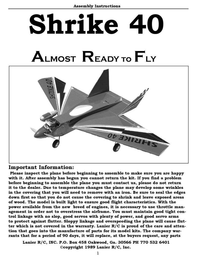
Lanier R/C Shrike 40 User manual

Lanier R/C

Lanier R/C Shrike 40 User manual

Lanier R/C Stinger .60 ARF User manual

Lanier R/C

Lanier R/C Stinger .60 ARF User manual

Lanier R/C MARINER 40 MK II ARF User manual

Lanier R/C

Lanier R/C MARINER 40 MK II ARF User manual

Lanier R/C STINGER 120 ARF User manual

Lanier R/C

Lanier R/C STINGER 120 ARF User manual

Lanier R/C Dart ARF Instruction Manual

Lanier R/C

Lanier R/C Dart ARF Instruction Manual

Lanier R/C ripper User manual

Lanier R/C

Lanier R/C ripper User manual

Lanier R/C S.E.5A User manual

Lanier R/C

Lanier R/C S.E.5A User manual

Lanier R/C 94" Edge 540 ARF User manual

Lanier R/C

Lanier R/C 94" Edge 540 ARF User manual

Lanier R/C MARINER 40 MK II ARF User manual

Lanier R/C

Lanier R/C MARINER 40 MK II ARF User manual

Lanier R/C MARINER 40 MK II ARF User manual

Lanier R/C

Lanier R/C MARINER 40 MK II ARF User manual

Lanier R/C MARINER 40 MK II ARF User manual

Lanier R/C

Lanier R/C MARINER 40 MK II ARF User manual

Lanier R/C MARINER 40 MK II ARF User manual

Lanier R/C

Lanier R/C MARINER 40 MK II ARF User manual

Lanier R/C MARINER 40 MK II ARF User manual

Lanier R/C

Lanier R/C MARINER 40 MK II ARF User manual

Lanier R/C Stinger 60 User manual

Lanier R/C

Lanier R/C Stinger 60 User manual

Lanier R/C MARINER 40 MK II ARF User manual

Lanier R/C

Lanier R/C MARINER 40 MK II ARF User manual

Lanier R/C EXPLORER 40 User manual

Lanier R/C

Lanier R/C EXPLORER 40 User manual

Lanier R/C P-51 Instruction Manual

Lanier R/C

Lanier R/C P-51 Instruction Manual

Lanier R/C MARINER .120 User manual

Lanier R/C

Lanier R/C MARINER .120 User manual

Lanier R/C MARINER .40 User manual

Lanier R/C

Lanier R/C MARINER .40 User manual

Lanier R/C MARINER 40 MK II ARF User manual

Lanier R/C

Lanier R/C MARINER 40 MK II ARF User manual

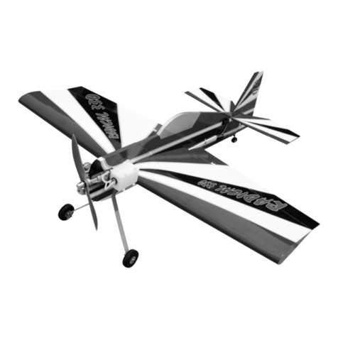
Lanier R/C Radical 330 ARF User manual

Lanier R/C

Lanier R/C Radical 330 ARF User manual

Lanier R/C Corsair ARF User manual

Lanier R/C

Lanier R/C Corsair ARF User manual

Popular Toy manuals by other brands

NextGen Citation CJ4X Tutorial

NextGen

NextGen Citation CJ4X Tutorial

BMI Albatros manual

BMI

BMI Albatros manual

Jamara X-Ray Instruction

Jamara

Jamara X-Ray Instruction

Eduard M-1130 CV Slat Armour quick start guide

Eduard

Eduard M-1130 CV Slat Armour quick start guide

Carrera Evolution 25189 Le Mans Contest Assembly and operating instructions

Carrera

Carrera Evolution 25189 Le Mans Contest Assembly and operating instructions

Fisher-Price CMH50 manual

Fisher-Price

Fisher-Price CMH50 manual

Fisher-Price L3479 instruction sheet

Fisher-Price

Fisher-Price L3479 instruction sheet

Goblin Urukay Competition user manual

Goblin

Goblin Urukay Competition user manual

Ravensburger Gravitrax Flip manual

Ravensburger

Ravensburger Gravitrax Flip manual

Eduard P-51D interior late ser.20-35 S.A. manual

Eduard

Eduard P-51D interior late ser.20-35 S.A. manual

Fisher-Price VOICE TECH RESCUE HEROES Wendy Waters... instructions

Fisher-Price

Fisher-Price VOICE TECH RESCUE HEROES Wendy Waters... instructions

Black Horce Model WESTLAND WYVERN BH112 Instruction manual book

Black Horce Model

Black Horce Model WESTLAND WYVERN BH112 Instruction manual book

REVELL Tornado GR1 RAF Assembly manual

REVELL

REVELL Tornado GR1 RAF Assembly manual

MD Helicopters MDHI MD900 instructions

MD Helicopters

MD Helicopters MDHI MD900 instructions

Banana Hobby BlitzRCWorks P-40N manual

Banana Hobby

Banana Hobby BlitzRCWorks P-40N manual

Phoenix Model KATANA-EP instruction manual

Phoenix Model

Phoenix Model KATANA-EP instruction manual

NOCH 14638 manual

NOCH

NOCH 14638 manual

Eduard B-17E/F exterior manual

Eduard

Eduard B-17E/F exterior manual

manuals.online logo
manuals.online logoBrands
  • About & Mission
  • Contact us
  • Privacy Policy
  • Terms and Conditions

Copyright 2025 Manuals.Online. All Rights Reserved.