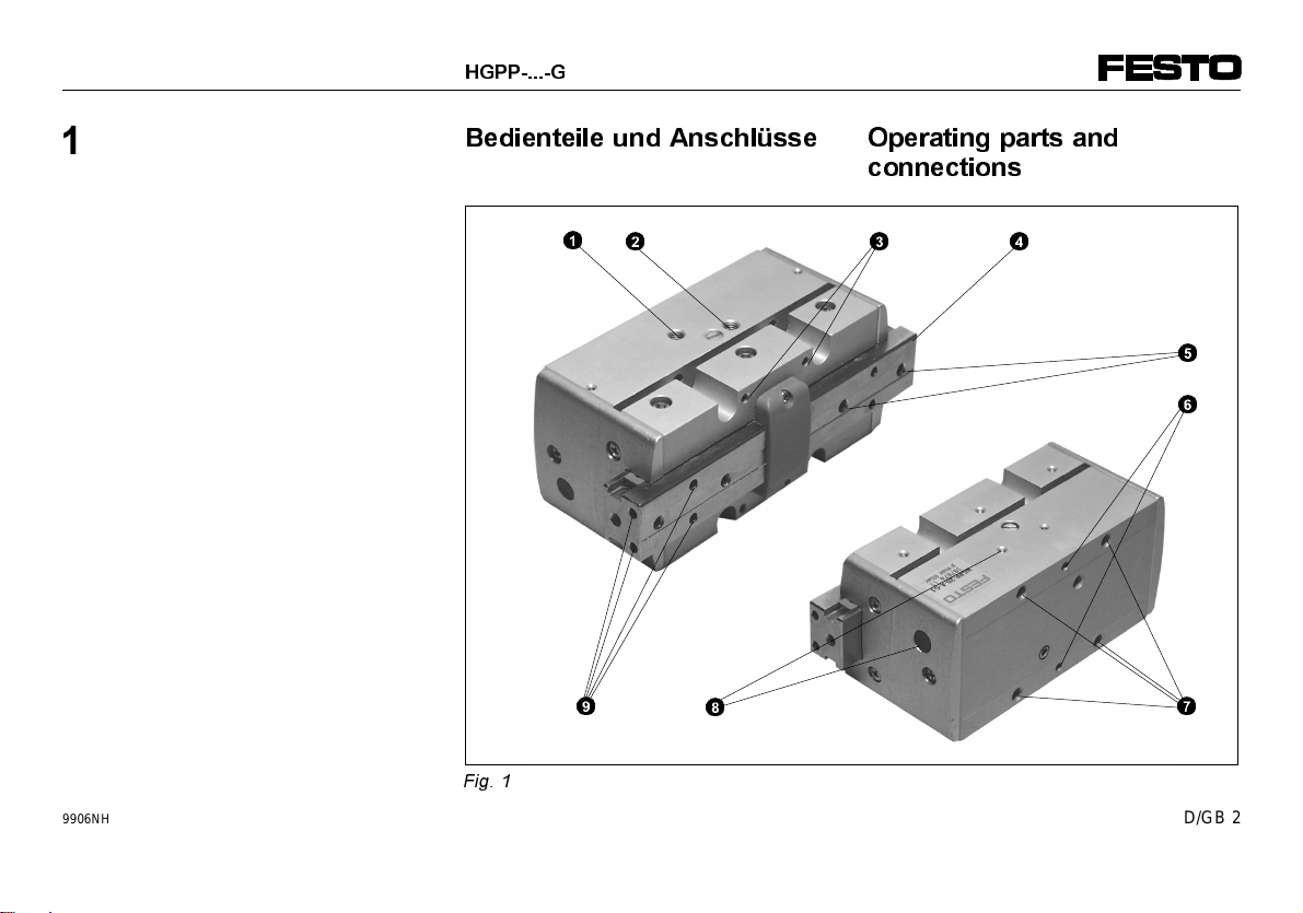
manuals.online logo
Brands
  1. Home
  2. •
  3. Brands
  4. •
  5. Festo
  6. •
  7. Industrial Equipment
  8. •
  9. Festo HGPP A Series User manual

Festo HGPP A Series User manual

%HGLHQXQJVDQOHLWXQJ
3Ul]LVLRQV*UHLIHU
7\S+*33$
2SHUDWLQJLQVWUXFWLRQV
3UHFLVLRQJULSSHU
W\SH+*33$
Einbau und Inbetriebnahme sind nur
durchzuführen von Fachpersonal mit
entsprechender Qualifikation gemäß Be-
dienungsanleitung.
Fitting and commissioning must be car-
ried out only by qualified technicians in
accordance with these operating instruc-
tions.
Es bedeuten:/Symbols:
Warnung
Warning, Caution
Hinweis
Note
Recycling
Recycling
Zubehör
Accessories
390 804
9906NH D/GB 1
%HGLHQWHLOHXQG$QVFKOVVH 2SHUDWLQJSDUWVDQG
FRQQHFWLRQV

123
9
6
5
4
7
8
)LJ
+*33* 
9906NH D/GB 2
1
2
3
4
5
6
7
8
9
Gewindebohrungen für Druckluft-
anschluß (Greifer außengreifend
schließen)
Gewindebohrungen für Druckluft-
anschluß (Greifer außengreifend
öffnen)
Gewindebohrungen für Niederhalter
Greifbacken
Gewindebohrungen für Greiffinger-
Montage
Passung für Greifer-Montage
Gewinde-/Durchgangsbohrungen
für Befestigungsschrauben
Bohrung mit querliegendem
Gewindestift für Sensorbefestigung
(Bohrung mit Stopfen verschlossen)
Passung für Greiffinger-Montage
(Greiffinger nicht im Lieferumfang
enthalten)
1
2
3
4
5
6
7
8
9
Threaded holes for compressed
air connection (close external
grippers)
Threaded holes for compressed
air connection (open external
grippers)
Threaded holes for fitting external
elements
Gripper jaws
Threaded holes for mounting
gripper fingers
Fitting for gripper mounting
Threaded/through holes for
fastening screws
Hole with transverse threaded
pin for fastening the sensor
(hole sealed with plug)
Fitting for gripper finger mounting
(gripper finger not included in
delivery)
9906NH D/GB 3
,QKDOW
 %HGLHQWHLOHXQG
$QVFKOVVH
. . . .. . . .. . . .. . . .. . 2
 ,QKDOW
. . . . . . . . . . . . . . . . . . . . . . . 4
 )XQNWLRQXQG$QZHQGXQJ
. . . . . 5
 9RUDXVVHW]XQJHQIUGHQ
3URGXNWHLQVDW]
. . . . . . . . . . . . . . . 6
 (LQEDX
. . . .. . . .. . . .. . . .. . . .. . 8
Einbau mechanisch. . . . . . . . . . . . 8
Einbau pneumatisch . . . . . . . . . . 14
 ,QEHWULHEQDKPH
. . . . . . . . . . . . . 17
Inbetriebnahme Gesamtanlage . 17
Inbetriebnahme Einzelgerät . . . . 18
 %HGLHQXQJXQG%HWULHE
. . . . . . 21
 :DUWXQJXQG3IOHJH
. . . . . . . . . 22
 =XEHK|U
. . . . . . . . . . . . . . . . . . . . 24
 6W|UXQJVEHVHLWLJXQJ
. . . . . . . . 25
 7HFKQLVFKH'DWHQ
. . . . . . . . . . . 26
 .HQQOLQLHQ
. . . . . . . . . . . . . . . . . . 30
&RQWHQWV
 2SHUDWLQJSDUWVDQG
FRQQHFWLRQV
. . . .. . . .. . . .. . . .. . 2
 &RQWHQWV
. . . . . . . . . . . . . . . . . . . . . 4
 )XQFWLRQDQGDSSOLFDWLRQ
. . . .. . 5
 &RQGLWLRQVRIXVH
. . . . . . . . . . . . . 6
 )LWWLQJ
. . . . . . . . . . . . . . . . . . . . . . . 8
Mechanical fitting . . . . . . . . . .. . . . 8
Pneumatic fitting. . . . . . . . . . . . . . 14
 &RPPLVVLRQLQJ
. . . . . . . . . . . . . . 17
Commissioning complete
system . . . . . . . . . . . . . . . . . . . . . . 17
Commissioning individual
units. . . . . . . . . . . . . . . . . . . . . . . . 18
 2SHUDWLRQ
. . . . . . . . . . . . . . . . . . . 21
 &DUHDQGPDLQWHQDQFH
. . . . . . . . 22
 $FFHVVRULHV
. . . . . . . . . . . . . . . . . 24
 (OLPLQDWLQJIDXOWV
. . . . . . . . . . . . 25
 7HFKQLFDOVSHFLILFDWLRQV
. . . . . . 28
 &KDUDFWHULVWLFFXUYHV
. . . . . . . . 30

+*33* 
9906NH D/GB 4
)XQNWLRQXQG$QZHQGXQJ
Durch wechselseitige Belüftung der
Druckluftanschlüsse
1
und
2
bewegen
sich zwei Kolben hin und her.
Eine Mechanik überträgt die Längsbe-
wegung der Kolben auf die Greifbacken
4
. An den Greifbacken werden Greiffin-
ger befestigt. Das Öffnen und Schließen
der Greiffinger klemmt Nutzlasten an
der Außen- oder Innenkontur.
Bei Entlüftung des Greifers sorgt eine
Rückstellfeder für die Rückführung der
Greifbacken in die Ausgangsposition:
- Greiffinger geöffnet: bei HGPP-...-G1
- Greiffinger geschlossen: HGPP-...-G2
Der Greifer HGPP-... ist doppeltwirkend
und daher sowohl außengreifend, als
auch innengreifend einsetzbar. Die Grei-
fervariante HGPP-...-G.. kann aufgrund
der Federrückstellung auch einfachwir-
kend eingesetzt werden.
Bestimmungsgemäß dient der HGPP-...
dem Greifen und Halten von Nutzlasten
in Handlingsprozessen.
)XQFWLRQDQGDSSOLFDWLRQ
When compressed air is applied alter-
nately to connections
1
and
2
, two pis-
tons move backwards and forwards.
A mechanism transfers the longitudinal
movement of the pistons to the gripper
jaws
4
. Gripper fingers are fastened to
the gripper jaws. When the jaws open,
they can grip work loads by the inner
contour; when the jaws close, they can
grip work loads by the outer contour.
When the gripper is exhausted, a reset
spring returns the gripper jaws to the
starting position:
- gripper fingers open: on HGPP-...-G1
- gripper fingers closed: on HGPP-...-G2
The HGPP-... gripper is double-acting
and can therefore be used for gripping
from the outside as well as from the in-
side. The gripper variant type HGPP-...-G..
can also be used as a single-acting
gripper due to the spring return.
The HGPP-... is designed for gripping
and holding work loads in handling pro-
cesses.

+*33*
)LJ
+*33*
)LJ
9906NH D/GB 5
9RUDXVVHW]XQJHQIUGHQ
3URGXNWHLQVDW]
+,1:(,6
'XUFKXQVDFKJHPlH+DQGKDEXQJ
HQWVWHKHQ)HKOIXQNWLRQHQ
•
6WHOOHQ6LHVLFKHUGDGLH+LQ
ZHLVHGLHVHV.DSLWHOVVWHWVHLQ
JHKDOWHQZHUGHQ
'LHVPDFKWGDV3URGXNWYHUKDOWHQ
RUGQXQJVJHPlXQGVLFKHU
•Vergleichen Sie die Grenzwerte in
dieser Bedienungsanleitung mit
Ihrem aktuellen Einsatzfall (z.B. für
Drücke, Kräfte, Momente, Massen,
Geschwindigkeiten, Temperaturen).
•Sorgen Sie für Druckluft mit
ordnungsgemäßer Aufbereitung.
•Berücksichtigen Sie die Umgebungs-
bedingungen vor Ort.
&RQGLWLRQVRIXVH
3/($6(127(
0DOIXQFWLRQLQJFDQRFFXUDVDUHVXOW
RILQFRUUHFWKDQGOLQJ
•
0DNHVXUHWKDW\RXDOZD\V
REVHUYHWKHLQVWUXFWLRQVOLVWHG
LQWKLVFKDSWHU
7KHSURGXFWZLOOWKHQIXQFWLRQ
FRUUHFWO\DQGUHOLDEO\
•Compare the limit values in these
operating instructions with your
current application (e.g. for press-
ures, forces, torques, masses,
speeds, temperatures).
•Make sure that there is a correctly
prepared supply of compressed air.
•Take into account the ambient con-
ditions at your location.

LDF-... LR-...
LF-...
)LJ
C%mbar
)LJ
+*33* 
9906NH D/GB 6
•Please observe the national and/or
local technical regulations for your
location.
•Remove the packing.
The packing is intended for recycling
purposes.
•Use dry and non-lubricated com-
pressed air for the entire service life
of the product.
An intermediate change to lubricated
compressed air will ruin the service
life lubrication of the product.
•Pressurize the complete system
slowly (e.g. with a safety start-up
valve of type HEL-... or HEM-...).
Uncontrolled movements of the actu-
ators will not then occur.
•Use the product in its original condi-
tion without undertaking any modifi-
cations.
•Please observe the warnings and
instructions on the product and in
these operating instructions.
•Beachten Sie die Vorschriften Ihres
Einsatzortes z.B. von Berufsgenossen-
schaft, oder nationalen Institutionen.
•Entfernen Sie die Verpackungen.
Die Verpackungen sind vorgesehen
für eine Verwertung auf stofflicher
Basis.
•Verwenden Sie Druckluft trocken
und ungeölt über die gesamte Pro-
duktlebensdauer.
Zwischenzeitlicher Wechsel zu geöl-
ter Druckluft zersetzt die Lebensdau-
erschmierung.
•Belüften Sie die Anlage insgesamt
langsam (z.B mit einem Sicherheits-
Einschaltventil Typ HEL-... oder
HEM-...).
Dann treten Bewegungen der Aktorik
nur kontrolliert auf.
•Verwenden Sie das Produkt im Origi-
nalzustand ohne jegliche eigenmäch-
tige Veränderung.
•Berücksichtigen Sie die Warnungen
und Hinweise am Produkt und in
dieser Bedienungsanleitung.
)LJ
)LJ
9906NH D/GB 7
)LWWLQJ
0HFKDQLFDOILWWLQJ
Mounting the gripper fingers
3/($6(127(
([FHVVLYHIRUFHVRUWRUTXHVFDQ
GDPDJHWKHJULSSLQJPHFKDQLVP

•
0DNHVXUHWKDWWKHIROORZLQJ
YDULDEOHVDUHQRWH[FHHGHG
± WKHPD[LPXPSHUPLWWHGWLJKWHQLQJ
WRUTXHVIRUPRXQWLQJWKHJULSSHU
ILQJHUV
± WKHPD[LPXPVFUHZLQJGHSWKRI
WKHIDVWHQLQJVFUHZVRQWKH
JULSSHUMDZV
± WKHPD[LPXPSHUPLWWHGYDOXHV
IRUIRUFH)DQGWRUTXHV0VHH
VHFWLRQ7HFKQLFDOVSHFLILFDWLRQV
± WKHJULSSHUILQJHUVVKRXOGEHDV
VKRUWDVSRVVLEOH
± WKHJULSSHUILQJHUVVKRXOGEHDV
OLJKWDVSRVVLEOH
(LQEDX
(LQEDXPHFKDQLVFK
Zur Greiffingermontage:
+,1:(,6
=XJURH.UlIWHRGHU0RPHQWH]HU
VW|UHQGHQ*UHLIPHFKDQLVPXV
•
%HDFKWHQ6LHGLH(LQKDOWXQJ
IROJHQGHU*U|HQ
± GLH]XOlVVLJHQ$Q]LHKGUHK
PRPHQWHEHLGHU*UHLIILQJHU
0RQWDJH
± GLHPD[LPDOH(LQVFKUDXEWLHIHGHU
%HIHVWLJXQJVVFKUDXEHQDP
*UHLIEDFNHQ
± GLHPD[LPDO]XOlVVLJHQ:HUWHIU
.UDIW)XQG0RPHQWH0VLHKH
KLHU]X.DSLWHO7HFKQLVFKH'DWHQ
± HLQHP|JOLFKVWJHULQJH*UHLI
ILQJHUOlQJH
± HLQP|JOLFKVWJHULQJHV*UHLI
ILQJHUJHZLFKW
)LJ

+*33* 
9906NH D/GB 8
•Behandeln Sie die Greifbacken sorg-
fältig.
Beschädigungen mindern die Funkti-
onssicherheit.
•Drücken Sie einen Paßstift in jede
Passung der Greiffinger (Durchmes-
ser siehe Fig. 11).
•Positionieren Sie die Greiffinger an
den Greifbacken mit Hilfe der Paßstif-
te.
•Beachten Sie die zulässige Grenze
der Anziehdrehmomente.
Zu große Anziehdrehmomente zer-
stören den Greifmechanismus.
•Drehen Sie je zwei Befestigungs-
schrauben in die Gewindebohrungen
der Greifbacken.
•Handle the gripper jaws with great
care.
Damage will reduce the functional
reliability.
•Press a dowel pin into each fitting
for the gripper fingers (diameter see
fig. 11).
•Position the gripper fingers on the
gripper jaws with the aid of the
dowel pins.
•Observe the maximum limits for the
tightening torques.
Excessive tightening torques may
damage the gripping mechanism.
•Insert two fastening screws into the
threaded holes of the gripper jaws.
)LJ
)LJ
9906NH D/GB 9
The different gripper jaws have the fol-
lowing sizes:
HGPP-
12-A HGPP-
16-A HGPP-
20-A
Jaw width 12.5 mm 16 mm 20 mm
Fitting 2H8 mm 2.5H8mm 3H8mm
Thread
size M3 M3 M4
Max.
permitted
screwing
depth
6 mm 6 mm 8 mm
Max. tighte-
ning torque 1.2 Nm 1.2 Nm 2.9 Nm
)LJ
For scanning the position of the gripper
piston:
•use sensors of type
SMH-S1-HGPP-...-A.
These increase the total width of the
gripper.
Die unterschiedlichen Greifbacken ha-
ben folgende Kenngrößen:
HGPP-
12-A HGPP-
16-A HGPP-
20-A
Backenbreite 12,5 mm 16 mm 20 mm
Passung 2H8 mm 2,5H8mm 3H8mm
Nenn-
gewinde M3 M3 M4
Max.
zulässige
Einschraub-
tiefe
6 mm 6 mm 8 mm
Max. Anzieh-
drehmoment 1,2 Nm 1,2 Nm 2,9 Nm
)LJ
Zur Positionsabfrage des Greiferkol-
bens:
•Verwenden Sie Sensoren vom Typ
SMH-S1-HGPP-...-A.
Diese erhöhen die Gesamtbreite des
Greifers.
+*33* 
9906NH D/GB 10
•Fasten the sensor as follows:
1. Remove the plug.
2. Unscrew the transverse threaded
pin
8
.
3. Push the sensor into the hole
8
as far as possible (check that
it is not distorted and align the
cable exit).
4. Fasten the sensor with the
threaded pin (tightening torque
see instructions with Hall sensor).
Fitting the HGPP-...:
3/($6(127(
+LJKDFFHOHUDWLRQIRUFHVLQWKH
ORQJLWXGLQDOGLUHFWLRQRIWKHJULSSHU
HJZKHQILWWHGRQPRYLQJSDUWV
VXFKDVWKH'*3UHGXFHWKH
JULSSLQJIRUFH
•
0DNHVXUHWKDWWKHUHVXOWLQJ
ZRUNORDGIRUFHVOLHZLWKLQ
WKHUHGXFHGJULSSLQJIRUFH
UDQJH
•Befestigen Sie den Sensor wie folgt:
1. Stopfen entfernen
2. Querliegenden Gewindestift
8
ausdrehen.
3. Sensor in die Bohrung
8
bis zum
Anschlag einschieben (Verdreh-
sicherung und Kabelabgang aus-
richten).
4. Sensor mit dem Gewindestift befe-
stigen (Anziehdrehmoment siehe
Beipackzettel des Hall-Sensors).
Zur Montage des HGPP-...:
+,1:(,6
+RKH%HVFKOHXQLJXQJVNUlIWHLQ
/lQJVULFKWXQJGHV*UHLIHUV]%
EHL0RQWDJHDXIEHZHJWHQ7HLOHQ
ZLH'*3UHGX]LHUHQGLH*UHLI
NUDIW
•
6WHOOHQ6LHVLFKHUGDGLH
UHVXOWLHUHQGHQ1XW]ODVWNUlIWH
LQQHUKDOEGHVUHGX]LHUWHQ
*UHLINUDIWEHUHLFKVOLHJHQ
3. 4
.
)LJ
)LJ
9906NH D/GB 11
•Check whether adapter plates are
necessary.
Adapter plates enable the HGPP-...
to be connected to Festo handling
components (see section "Acces-
sories").
•Place the HGPP.-... as near as
possible to the compressed air sup-
ply (short tubing).
This will lead to shorter pressuriza-
tion times.
•Select one of the following methods
of fastening:
– direct fastening from the front
(fastening screw one size
smaller)
– direct fastening from the rear.
•Fasten the HGPP-... as follows:
– Insert the dowel pins (a) in the
fittings
6.
– Place the gripper with dowel pins
on the fastening surface.
– Screw in four screws (b) for
fastening.
•Prüfen Sie die Notwendigkeit von
Adapterplatten.
Die Verbindung des HGPP-... mit
Festo-Handlingskomponenten wird
durch Adapterplatten ermöglicht (sie-
he "Zubehör").
•Plazieren Sie den HGPP.-... mög-
lichst nahe an die Druckluftversor-
gung (kurze Schlauchleitungen).
Dies führt zu kürzeren Belüftungszei-
ten.
•Wählen Sie eine der folgenden
Befestigungsmöglichkeiten:
– Direktbefestigung von vorne (Befe-
stigungsschraube eine Nennweite
kleiner wählen)
– Direktbefestigung von hinten.
•Befestigen Sie den HGPP-... wie
folgt:
– Paßstifte (a) in die Passungen
6
stecken.
– Greifer mit Paßstiften auf Anschluß-
fläche plazieren.
– Vier Schrauben (b) zur Befestigung
eindrehen.
(b)
(a)
)LJ
+*33* 
9906NH D/GB 12
The values are summarized in the follow-
ing table.
Tolerance
field HGPP-
12-A HGPP-
16-A HGPP-
20-A
Fitting
diameter H8333
Fitting
depth 0.1677
Size M 4
(M 3) M 4
(M 3) M 5
(M 4)
Max.
tightening
torque 2.9 Nm
(1.2 Nm) 2.9 Nm
(1.2 Nm) 5.8 Nm
(2.9 Nm)
)LJ
Die Kennwerte sind in der nachfolgen-
den Tabelle zusammengefaßt:
Toleranz-
feld HGPP-
12-A HGPP-
16-A HGPP-
20-A
Passungs-
durch-
messer H8333
Passungs-
tiefe 0,1677
Nenn-
weite M 4
(M 3) M 4
(M 3) M 5
(M 4)
Max. An-
ziehdreh-
moment 2,9 Nm
(1,2 Nm) 2,9 Nm
(1,2 Nm) 5,8 Nm
(2,9 Nm)
)LJ
9906NH D/GB 13
3QHXPDWLFILWWLQJ
3/($6(127(
'LUWFDQEORFNWKHJULSSHUSLVWRQ
•
0DNHVXUHWKDWWKHUHDUHQRGLUW
SDUWLFOHVRUIRUHLJQREMHFWVLQWKH
SQHXPDWLFFRQQHFWLRQRIWKH
JULSSHURULQWKHWXELQJ
In the case of grippers which are not
protected against the load sliding down:
•Check to see if the accessories in
the table below are required.
Accessory Purpose
Compensating
reservoir of
type VZS-...
This helps to reduce
fluctuations in pressure.
Safety start-up
valve of type
HGL-...
You can avoid the work
load falling down
suddenly if there is a
drop in pressure.
)LJ
•Use only Festo screw connectors
(e.g. type QS-...).
(LQEDXSQHXPDWLVFK
+,1:(,6
9HUXQUHLQLJXQJHQEORFNLHUHQGLH
*UHLIHUNROEHQ
•
6WHOOHQ6LHVLFKHUGDVLFKNHLQH
6FKPXW]SDUWLNHORGHU)UHPGN|USHU
LPSQHXPDWLVFKHQ$QVFKOXGHV
*UHLIHUVRGHULQGHQ6FKODXFK
OHLWXQJHQEHILQGHQ
Bei Greifern ohne Greifkraftsicherung:
•Prüfen Sie die Notwendigkeit folgen-
den Zubehörs:
Zubehör Wirkungsweise
Ausgleichs-
speicher vom
Typ VZS-...
Dadurch werden
Druckschwankungen
reduziert.
Sicherheits-
ventil vom
Typ HGL-...
Bei schlagartigem
Druckabfall vermeiden Sie
damit ein plötzliches
Abwärtsfallen der Nutzlast.
)LJ
•Verwenden Sie vorzugsweise Festo-
Verschraubungen (z.B. Typ QS-...).
+*33* 
9906NH D/GB 14
•Connect the compressed air tubing
to the connections
1
and
2
accord-
ing to your individual application.
•Verschlauchen Sie die Druckluftan-
schlüsse
1
und
2
nach Ihrem Ein-
satzfall.
)LJ
)LJ
Druckluft-
anschluß
1
Druckluft-
anschluß
2
HGPP-... Außengreifend Schließen Öffnen
Innengreifend Öffnen Schließen
Compressed
air port
1
Compressed
air port
2
HGPP-... External grip Close Open
Internal grip Open Close
9906NH D/GB 15
The alternative connections are sealed
with blind plugs.
If you are using long and heavy gripping
fingers:
•connect a one-way flow control valve
of type GRLZ-... or GRLA-... directly
to each compressed air connection.
The closing time (and thereby also
the loading of the bearing) of the
gripper fingers can be modified if
one-way flow control valves are used.
In the case of short and light gripper
fingers, the fixed restrictor already in-
corporated renders the use of an
extra external restrictor unnecessary.
Die Alternativanschlüsse sind mit Blind-
stopfen verschlossen.
Bei Verwendung langer und schwerer
Greiffinger:
•Verwenden Sie direkt an den Druck-
luftanschlüssen je ein Drosselrück-
schlagventil GRLZ-... oder GRLA-... .
Durch die Drosselrückschlagventile
kann die Schließzeit (und damit die
Lagerbelastung) der Greiffinger ver-
ändert werden.
Die bereits integrierte Festdrossel er-
möglicht bei kurzen und leichten
Greiffingern einen Verzicht auf eine
zusätzliche, externe Drosselung.
)LJ
+*33* 
9906NH D/GB 16

)LJ
,QEHWULHEQDKPH
Zum Justieren des Sensors:
•Vollziehen Sie die Sensoreinstellun-
gen anhand der beigefügten Sensor-
bedienungsanleitungen.
•Positionieren Sie die Greifer-Kolben
stets mit Druckluft in die gewünschte
Endlage.
Die Kolbenlage des mechanisch posi-
tionierten Greifbackens entspricht
nicht der Position im Betrieb.
,QEHWULHEQDKPH*HVDPWDQODJH
•Belüften Sie Ihre gesamte Anlage
langsam.
Dann treten keine unkontrollierten
Bewegungen auf.
Zur langsamen Einschaltbelüftung
dient das Sicherheits-Einschaltventil
Typ HEL-... oder HEM-... .
&RPPLVVLRQLQJ
In order to adjust the sensor:
•carry out the necessary settings as
described in the operating instructions
of the sensor.
•Always move the gripper pistons into
the desired end positions using com-
pressed air.
The piston position of the mechanically
actuated gripper jaw is not the same
as the position during operation.
&RPPLVVLRQLQJFRPSOHWHV\VWHP
•Slowly pressurize the complete sys-
tem.
This will prevent uncontrolled move-
ments of the actuators.
For slow pressurization when start-
ing, use safety start-up valves of type
HEL-... or HEM-... .
9906NH D/GB 17
,QEHWULHEQDKPH(LQ]HOJHUlW
•Achten Sie auf die zulässigen Werte
für:
– die maximale Greifkraft in Abhän-
gigkeit vom Hebelarm (siehe Ka-
pitel "Kennlinien"):
•
außengreifend
•
innengreifend
– die maximale Greifkraft in Abhän-
gigkeit der Exzentrizität der Greif-
finger (siehe Kapitel "Kennlinien").
– die Schließzeit in Abhängigkeit der
Gewichtskraft der Greiffinger (siehe
"Technische Daten").
Die Gewichtskraft der Greiffinger soll-
te berechnet worden sein.
&RPPLVVLRQLQJLQGLYLGXDOXQLWV
•Please observe the permitted values
for:
– the maximum gripping force as a
factor of the lever arm (see section
"Characteristic curves"):
•
when gripping externally
•
when gripping internally
– the maximum gripping force as a
factor of the eccentricity of the grip-
per fingers (see section "Charac-
teristic curves").
– the closing time as a factor of the
weight force of the gripper fingers
(see section "Technical specifica-
tions").
The weight force of the gripper
fingers should be calculated.
+*33* 
9906NH D/GB 18
:$51,1*
7KHUHLVDGDQJHURIILQJHUVEHLQJ
VTXDVKHGEHWZHHQWKHJULSSHUMDZV
•
0DNHVXUHWKHUHIRUHWKDW
± QRERG\FDQSODFHKLVKHUKDQGV
EHWZHHQWKHJULSSHUILQJHUV
± QRIRUHLJQREMHFWVOLHLQWKHUDQJH
RIWKHJULSSHUVIRUH[DPSOH
E\PHDQVRIDSURWHFWLYHVFUHHQ
Setting the closing time
•Tighten the restrictor screws of the
upstream GRLA-... /GRLZ-...
– at first completely
– then open again approximately
one turn.
•Start a test run in the sequence
specificed below:
Test run Checks to be made
Without
work load – Compressed air
connections must be
assigned correctly
– Gripping speed
– Sensor functions
With
work load – Work load must be
held firmly
)LJ
:$5181*
*OLHGPDHQN|QQHQGXUFKEHZHJWH
%DXWHLOHJHTXHWVFKWZHUGHQ
•
6WHOOHQ6LHVLFKHUGDLP*UHLI
EHUHLFK
± QLHPDQG]ZLVFKHQGLH*UHLIILQJHU
IDW
± VLFKNHLQH)UHPGJHJHQVWlQGH
EHILQGHQ
]%GXUFK6FKXW]JLWWHU
Zur Einstellung der Schließzeit:
•Drehen Sie die Drosselschrauben der
vorgeschalteten GRLA-... /GRLZ-...
– zunächst ganz ein,
– dann wieder etwa eine Umdrehung
heraus.
•Starten Sie einen Probelauf in der
angegebenen Reihenfolge:
Probelauf Prüfungen
Ohne Nutzlast – Richtiger Zuordnung
der Druckluft-
anschlüsse
– Greifgeschwindigkeit
– Sensorenfunktion
Mit Nutzlast – Sicheres Festhalten der
Nutzlast
)LJ
)LJ
9906NH D/GB 19
1. Listen to the knock of the piston.
Piston knock
Soft Metallic
Tighten the
restrictor screw
one turn.
The maximum
gripping speed has
been reached.
Continue test run
with points 2 and 3 Conclude test run.
)LJ
2. Loosen the restrictor screws of the
upstream GRLA-... / GRLZ-... by one
turn.
3. Repeat points 1 and 2 until the
desired gripping speed is reached.
•Conclude the test run.
•Exhaust the gripper.
1. Horchen Sie auf das Anschlagen des
Kolbens:
Kolbenanschlag
Weich Metallisch
Drosselschraube
eine Umdrehung
eindrehen.
Die maximale
Greifgeschwindigkeit
ist erreicht.
Probelauf mit Punkt
2 und 3 fortsetzen Probedurchlauf
beenden
)LJ
2. Drehen Sie die Drosselschrauben der
vorgeschalteten GRLA-... / GRLZ-...
um eine Umdrehung heraus.
3. Wiederholen Sie Punkt 1 und 2 bis die
gewünschte Greifgeschwindigkeit er-
reicht ist.
•Beenden Sie den Probedurchlauf.
•Entlüften Sie den Greifer.
+*33* 
9906NH D/GB 20

This manual suits for next models

3

Other Festo Industrial Equipment manuals

Festo FLSM Series User manual

Festo

Festo FLSM Series User manual

Festo EGSS-BS User manual

Festo

Festo EGSS-BS User manual

Festo BV-200 Series User manual

Festo

Festo BV-200 Series User manual

Festo ELGA-BS-KF-80 User manual

Festo

Festo ELGA-BS-KF-80 User manual

Festo FRC D Series User manual

Festo

Festo FRC D Series User manual

Festo Checkbox Compact CHB-C-F Owner's manual

Festo

Festo Checkbox Compact CHB-C-F Owner's manual

Festo ELGT-BS User manual

Festo

Festo ELGT-BS User manual

Festo MS6 Series User manual

Festo

Festo MS6 Series User manual

Festo ELGC-BS-KF Parts list manual

Festo

Festo ELGC-BS-KF Parts list manual

Festo DGST-8 User manual

Festo

Festo DGST-8 User manual

Festo MS6-SV Series User manual

Festo

Festo MS6-SV Series User manual

Festo MPS 8038623 Service manual

Festo

Festo MPS 8038623 Service manual

Festo DMSP Series User manual

Festo

Festo DMSP Series User manual

Festo CTEU-EC Operating and installation instructions

Festo

Festo CTEU-EC Operating and installation instructions

Festo EPCE-TB User manual

Festo

Festo EPCE-TB User manual

Festo EXCH-40-...-W Series User manual

Festo

Festo EXCH-40-...-W Series User manual

Festo MS6-SV-C-MK User manual

Festo

Festo MS6-SV-C-MK User manual

Festo ADN-KP Series Setup guide

Festo

Festo ADN-KP Series Setup guide

Festo CLR-12 User manual

Festo

Festo CLR-12 User manual

Festo YXC Series User manual

Festo

Festo YXC Series User manual

Festo VABD Series User manual

Festo

Festo VABD Series User manual

Festo ELGA-TB-G User manual

Festo

Festo ELGA-TB-G User manual

Festo EHPS-16 Parts list manual

Festo

Festo EHPS-16 Parts list manual

Festo Belt Drives 2 Instructions for use

Festo

Festo Belt Drives 2 Instructions for use

Popular Industrial Equipment manuals by other brands

SICK EventCam EVC625-CCOXAL5L operating instructions

SICK

SICK EventCam EVC625-CCOXAL5L operating instructions

ABB HT580403 Operation manual

ABB

ABB HT580403 Operation manual

Siemens ET 200iSP Product information

Siemens

Siemens ET 200iSP Product information

Haas Automatic Pallet Changer Operator's manual

Haas

Haas Automatic Pallet Changer Operator's manual

Trinity Highway MPS 350X Product Description Assembly Manual

Trinity Highway

Trinity Highway MPS 350X Product Description Assembly Manual

TRI tool BEVELMASTER 212B instructions

TRI tool

TRI tool BEVELMASTER 212B instructions

Titan ParaMax owner's manual

Titan

Titan ParaMax owner's manual

Telesis BenchMark 200 manual

Telesis

Telesis BenchMark 200 manual

Shini SAL-330 manual

Shini

Shini SAL-330 manual

ABB ACS1000i air-cooled user manual

ABB

ABB ACS1000i air-cooled user manual

AUMA FQM Operation instructions

AUMA

AUMA FQM Operation instructions

Taylor Tools Bronco 260P-HL owner's manual

Taylor Tools

Taylor Tools Bronco 260P-HL owner's manual

ABB HT577209 Operation manual

ABB

ABB HT577209 Operation manual

Sapphire Audio 2500HS Operation manual

Sapphire Audio

Sapphire Audio 2500HS Operation manual

Columbus McKinnon MAGNETEK LaserGuard Mini Technical manual

Columbus McKinnon

Columbus McKinnon MAGNETEK LaserGuard Mini Technical manual

Climax KM3000 operating manual

Climax

Climax KM3000 operating manual

Tormach ATC Operator's manual

Tormach

Tormach ATC Operator's manual

FLENDER RUPEX RWN Assembly and operating instructions

FLENDER

FLENDER RUPEX RWN Assembly and operating instructions

manuals.online logo
manuals.online logoBrands
  • About & Mission
  • Contact us
  • Privacy Policy
  • Terms and Conditions

Copyright 2025 Manuals.Online. All Rights Reserved.