List of figures
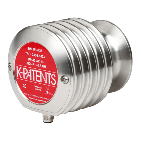
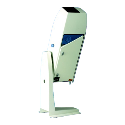
Figure 1 Sensor LPH, model PR-21-S............................................................................10
Figure 2 Refractometer equipment PR-21-S.............................................................. 10
Figure 3 Labels.....................................................................................................................11
Figure 4 Sensor structure.................................................................................................12
Figure 5 Image detector system.................................................................................... 13
Figure 6 Mounting guide 1/2........................................................................................... 15
Figure 7 Mounting guide 2/2.......................................................................................... 16
Figure 8 Sandvik LPL and LPS........................................................................................17
Figure 9 Flange LPL and LPS.......................................................................................... 18
Figure 10 DIN, JIS and ANSI 150lbs or 300lbs flanges...............................................19
Figure 11 Mounting procedure........................................................................................20
Figure 12 Indicating transmitter dimensions and mounting feet measures.......23
Figure 13 Wiring of PR-21-S with DTR...........................................................................24
Figure 14 Opening indicating transmitter front panel.............................................. 27
Figure 15 External power switch.....................................................................................28
Figure 16 Motherboard (AC power)...............................................................................29
Figure 17 Motherboard (24 V DC)..................................................................................30
Figure 18 Location of reset button.................................................................................34
Figure 19 Mounting of integral steam nozzles with DIN, JIS, ANSI
and Sandvik connections................................................................................37
Figure 20 Mounting summary of integral prism wash system................................38
Figure 21 Mounting drawing for integral high‑pressure wash system.................40
Figure 22 Wiring drawing: High‑pressure wash system for water..........................41
Figure 23 Prism wash with flow through cells.............................................................42
Figure 24 Flow through cell nozzles...............................................................................43
Figure 25 Main display alternatives................................................................................45
Figure 26 DTR keyboard and Main menu for sensor B..............................................48
Figure 27 Display setup menu......................................................................................... 49
Figure 28 Main display format selection.......................................................................49
Figure 29 System description............................................................................................51
Figure 30 Typical optical images.....................................................................................52
Figure 31 A slope graph.....................................................................................................52
Figure 32 Exponential damping...................................................................................... 55
Figure 33 Linear damping.................................................................................................56
Figure 34 Slew rate damping............................................................................................57
Figure 35 Eect of tolerance time on output.............................................................. 59
Figure 36 Damping stops during hold...........................................................................60
Figure 37 Relay menu for relay 1...................................................................................... 61
Figure 38 Output menu for mA Output 1......................................................................65
Figure 39 Default mA output values..............................................................................66
Figure 40 Concentration calibration layers...................................................................67
Figure 41 Using FIELD SAMPLE soft key...................................................................... 70
Figure 42 Automatic prism wash cycle...........................................................................71
Figure 43 Wash logic.......................................................................................................... 73
Figure 44 Wash cycle..........................................................................................................75
Figure 45 Mechanical zero adjustment..........................................................................78
Figure 46 Sensor rangeability.......................................................................................... 78
Figure 47 Ribbon cable connector.................................................................................. 81
Figure 48 Transmitter card positions............................................................................. 83
Figure 49 Motherboard PR‑10600 and H1 interface card PR‑10701...................... 84
Figure 50 Troubleshooting blank display......................................................................85
Figure 51 Checking power supply.................................................................................. 86
PR-21 Series User Guide IM-EN-PR21S-C
4
