Lauda PD 2 User manual

Operating Instructions
PuridestMono Distillation Apparatus
PD 2, PD 4

2 / 22 Puridest Mono Distillation Apparatus 09/2020

0
9
/2020
Puridest Mono Distillation Apparatus
3
/
22
LAUDA Puridest Mono Distillation Apparatus models PD 2 and PD 4 produce distillate of good quality with a low conduc-
tivity (approx. 2.3 µS / cm at 25 °C), dependent on quality andcomposition ofthe feed water.
Before installation, please check whether contents of package are in good order and complete.
Should younote any damages or have anyreasons for complaint, please contact your supplier or directly:
LAUDA-GFL Gesellschaft für Labortechnik mbH
Schulze-Delitzsch-Str. 4+5
30938 Burgwedel - Germany
Telefon: +49(0)5139 9958 0
Fax: +49 (0)5139 995821
E-Mail: info@lauda-gfl.de
Internet: www.gfl.de

4 / 22 Puridest Mono Distillation Apparatus 09/2020

0
9
/2020
Puridest Mono Distillation Apparatus
5
/
22
Contents
Operating Instructions...................................................................................................................................................................1
1 Use of the Distillation Apparatus..........................................................................................................................................7
Intended Use...................................................................................................................................................................................7
1.1
Improper Use..................................................................................................................................................................................7
1.2
2 Warranty................................................................................................................................................................................7
3 Before Initiation.....................................................................................................................................................................8
4 Set-up and Location of the Distillation Apparatus...............................................................................................................8
5 Operating Voltage.................................................................................................................................................................8
6 Water Connections................................................................................................................................................................9
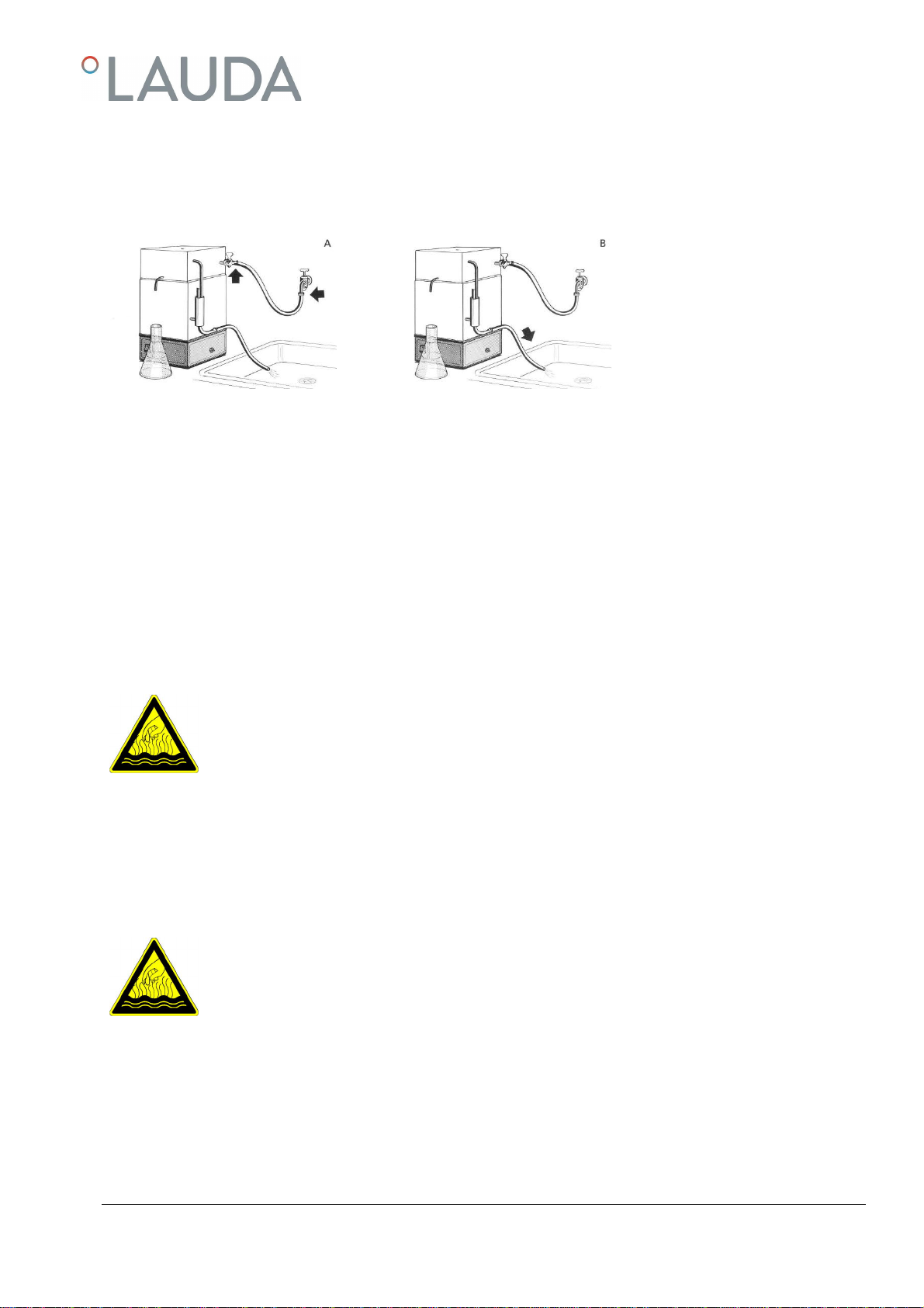
Tap water inlet (ill. A).....................................................................................................................................................................9
6.1
Cooling water outlet (ill. B)...........................................................................................................................................................9
6.2
Destillate Outlet.............................................................................................................................................................................9
6.3
7 Initiation and Setting of the CoolingWaterTemperature.................................................................................................10
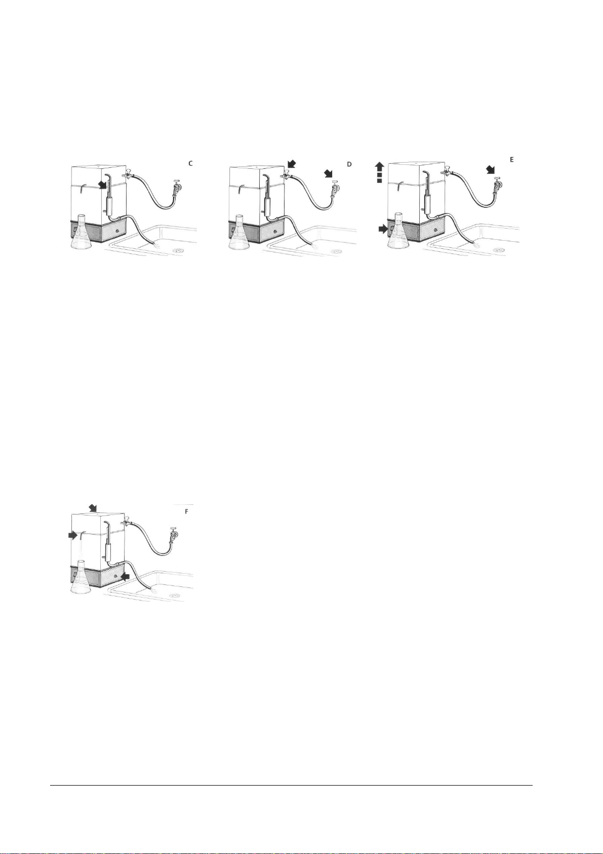
Control Thermometer (ill.C).....................................................................................................................................................10
7.1
Water inlet andSetting the Cooling Water Temperature (ill. D and E).............................................................................10
7.2
Degassing and Distillate Withdrawal (ill. F).............................................................................................................................10
7.3
8 FunctionalDescription.......................................................................................................................................................11
9 Maintenance,Service and Removal of Malfunctions.........................................................................................................11
Descaling........................................................................................................................................................................................11
9.1
Cleaning.........................................................................................................................................................................................12
9.2
Re-Initiation after Low Water....................................................................................................................................................12
9.3
10 Disposal of Old Units..........................................................................................................................................................12
11 TechnicalData....................................................................................................................................................................13
12 Circuit diagram...................................................................................................................................................................14
Circuit diagram PD 2..................................................................................................................................................................14
12.1
Circuit diagram PD 4..................................................................................................................................................................14
12.2
13 Connectionto the mains supply.........................................................................................................................................15
Electrical fuses..............................................................................................................................................................................15
13.1
Examples for connection to the mainssupply.........................................................................................................................16
13.2
14 List of spare parts................................................................................................................................................................ 17
15 Accessories..........................................................................................................................................................................18

6 / 22 Puridest Mono Distillation Apparatus 09/2020

0
9
/2020
Puridest Mono Distillation Apparatus
7
/
22
1 Use of the Distillation Apparatus
Intended Use
1.1
In LAUDA Puridest Mono Distillation Apparatus PD 2 andPD 4, an electric heating element serves to boil water and
transform it to steam. The steam is led into the condenser that is placed on the boiler and condenses onthe cooling coil.
The produced distillate drains through a drain tube on the front of the condenser. Depending on the model, the distillate
quantity is 2 litres (PD 2) or 4 litres (PD 4).
Dependingon the tap water quality, the produced distillate has a conductivity of approx. 2.3µS / cm at 25 °C. To feed
the Distillation Apparatus, preferably use tap water of drinking quality. Please also observe the information in chapters 15
of these instructions on the possible use of filters and cartridges to pretreat the tap water.
The Distillation Apparatus must be operated within the user's field of vision.
The information contained in these operating instructions must by all means beread and observed. Only
then a perfectoperation of the Distillation Apparatus can be guaranteed. The units may only be installed
and operated by persons who have made themselves familiar with these operating instructions.
Caution:
Both the outer housing ofthe boiler and the steam condenser get strongly heated up during operation.
Both partsmay only be touched after they have cooled down, or when using suitable safety gloves.
Improper Use
1.2
LAUDA Puridest Mono Distillation Apparatus, operated in a laboratory, are no Medical Devices. They fall neither under
national nor international Medical Device Directives and have to be used and applied accordingly. The Distillation Appa-
ratus maynot be used in potentiallyexplosivesurroundings. The Distillation Apparatusmay neither beset up nor operated
in laboratory areas with aggressive or corrosive ambient conditions.
2 Warranty
For all laboratory apparatus and their accessories fromLAUDA-GFL Gesellschaft für Labortechnik mbH, there is a war-
ranty claim, as well for spare parts, repairs and modifications, carriedout by LAUDA-GFL. In order to identify defective
units, we require both model and serial number on the nameplate, left-handside of the Distillation Apparatus and, if appli-
cable, a copyof the invoice.

8 / 22 Puridest Mono Distillation Apparatus 09/2020
3 Before Initiation
Important information are marked in boldletters in these instructions, safety indications are additionally marked by the
following warningsymbols and mandatory signs.
Read and observe the
operating instructions
Warning of hot liquids
and vapour Warning of hot surfaces
Warning of dangerous
electrical voltage General warning Before maintenance and repair
disconnect the unit all-pole from
the electrical mains (pull the plug
from the socket).
4 Set-up and Location of the Distillation Apparatus
All free openings of the water connections on the right-hand side of the unit are taped close. These
transport protections have to be removed before installation. Place on solid, even and level surfaces
inside buildings only. Make sure to place the unit only on a watertight, temperature-resistant, non-
flammable surface. The location must provide sufficient space as well as the necessary carrying capacity
for the unit (unit weight as per technical data, chapter 11 of this manual, plus weight of the filling. The
unit is not suitable for use in potentially explosive areas.
5 Operating Voltage
The Distillation Apparatus must be connected tothe mains through a correctly installedshock-proof
socket or through an on-site main switch. The Distillation Apparatus is a protection class Ielectrical
appliance, a connection to the earth conductor (PE) must be ensured. For information on the required
mains fuse please view Technical Data 11 of this manual.
The electrical connection must ensure an all-pole separation ofthe Distillation Apparatus from the
mains at any time. The mains connection cable must not touch any hotsurfaces of the unit. It may not
lead underneath the unit. Themain switch of the unit must be off (position O). The voltage on the
nameplate (at the back of the unit) must be identical to the mains voltage. If they are identical, connect
the unit to themains. For further information, please also refer to chapter 13 of these operating in-
structions "Connection to the Mains Supply".

0
9
/2020
Puridest Mono Distillation Apparatus
9
/
22
6 Water Connections
All water connections of the Distillation Apparatus, with theexception ofthe distillate withdrawal at the front, are located
at the right-hand side of the unit. Hoses for water inlet andoutlet are not included in the standard scope of supply.
Tap water inlet (ill. A)
6.1
Water is fed to the Distillation Apparatus through the tap water inlet. Connect a ½" pressure hose between the tap for
cooling water inlet and an on-site manualstop valve of the mains water supply. Make sure to secure both hose connections
with hose clips!
Cooling water outlet (ill. B)
6.2
Connect a ½" temperature-resistant hose witha maximum length of 1.5m to the cooling water outlet. The hose must
lead into a drain on a lower level and must have aslope on its complete length. Make sure the cooling water can drain with-
out back draughts.
Caution:
The cooling water leaves the Distillation Apparatus with a temperature up to 70 °C.
Danger ofscaldings!
Destillate Outlet
6.3
Use a temperature-resistant hose (not depicted)to connect the distillate outlet tube on the frontof the condenser with a
storage tank (to be providedon-site). When choosing the storage tank, observe thespecial storage conditions for distilled
water according to your requirements as well as the high temperature of freshly produced distillate.
Caution:
Distilled water leaves the Distillation Apparatus witha temperature up to 100 °C.
Danger ofscaldings!

10 / 22 Puridest Mono Distillation Apparatus 09/2020
7 Initiation and Setting of the Cooling Water Temperature
Lift the condenser from the boiler (ill.E, upwards arrow)and fill in water until the heatingelement in the boiler is com-
pletely covered by water.
Control Thermometer (ill. C)
7.1
Insert the supplied thermometer into the tubesupporton the right-handof the upper part.
Water inlet and Setting the Cooling Water Temperature (ill. D and E)
7.2
Open the tap of the cooling water supply on the unit completely (handle inthe direction of water flow), and the on-site
stop valve of the mains water supply a little. Check the power supply and switch on the mainswitch. The pilot lamp in the
main switch lights up. As soon as the water in the boiler reaches boilingpoint, regulate the cooling water supply on the tap
of the mains water supply so as to set the temperature of the draining cooling water to approx. 60 °C to 70°C. Thetem-
perature can be checked with the inserted thermometer. The Distillation Apparatus achieves its maximum efficiency witha
cooling water temperature of 60 °Cto 70 °C.
Degassing and Distillate Withdrawal (ill. F)
7.3
Carbon dioxide that forms during the distillation process, is released through a vent in the condenser. Produced distillate is
to be led through a hose (notshown) from the drain tube into a storagetank.

0
9
/2020
Puridest Mono Distillation Apparatus
11
/
22
8 Functional Description
The tap water flows through the cooling coil in the condenser to the water level regulator on the right-hand side of the
unit. The mechanical water level regulator determines the water level in the boiler so as to ensure that the heating element
is constantly kept below water level. Water that is not used forevaporation flows offthrough the cooling water outlet.
When the heating element is switched on, it brings the water in the alembic to the boil. Athermostatic low water cut-off
protects the heating element from running dry. The producedsteam is led into the condenser, condenses on the cooling
coil and drips off as distillate through the drain tube on the front. By setting the temperature of the cooling water between
60 °C and 70 °C, to be checked with the inserted thermometer, the unit's efficiency and the producedquantity of distil-
late is optimised.
9 Maintenance, Service and Removal of Malfunctions
Caution:
Before servicing the unit letthe Distillation Apparatus cool down!
Danger of burns!
Caution:
Before opening the Distillation Apparatus as well as before cleaning procedures, discon-
nect the unit from the mains! (Unplug the unitor switch off the main switch).
Danger of electrical shock!
Descaling
9.1
Dependingon the hardness of the tap water, the Distillation Apparatus must be
cleaned fromscale formations inregular intervals. To doso, close the on-site
water supply valve and lift the condenser fromthe boiler. A suitable descaling
agent is a mixture of 10 % formic acid, 10% acetic acid and80 % distilled water.
Fill the solvent into the boiler until it covers the topmost scale deposits andheat
up to maximum approx. 70 °C.Make absolutely certainnot to bring themixture
to a boil.
Pour thescale-solvent mix from the boiler after approx. 30 minutes and then rinsethe boiler thoroughly with tap water.
Commercial descaling agents, suitable for use with stainless steel, can also be used according to the manufacturer's in-
structions (e. g. rea-calc®of M/s CHEMOTEC GmbH, 63486Bruchköbel, Germany). Never useany products con-
taining hydrochloric acid! These will lead to damages to heatingelement, boiler, temperature sensor and the ducts of the
screw connections. Restart the unit as described in chapter 7.After descalings, the first few litres of distillateshould not
be used as it might contain traces of evaporated descaling agent.

12 / 22 Puridest Mono Distillation Apparatus 09/2020
Cleaning
9.2
Dependingon the degree of impurities inthe feed water and the growing contamination of the water in the boiler, caused
by the distilling process itself, the boiling process will cause foam formation. To prevent these impurities from migrating
into the pure water area of the condenser, the water in the boiler must beexchanged at least twice a week. To doso, close
the on-site water inlet valve and lift the condenser fromthe boiler. Thenempty the contents fromthe boiler and rinse
thoroughly with tap water.
Restart the unit as described in chapter 7.
The "Cleaning" procedure serves to exchange contaminated water in the boiler against clean water.
Re-Initiation after Low Water
9.3
In case of low water, the Distillation Apparatus temperature limiter will switch off the unit. In order
to restart, allow the unit to cool down and, as described in chapter 7, fill water into the boiler until
the heating element is below water level. Thetriggered low water cut-off must be released. To do
so, loosen the black cap nut at the right-hand bottom of the Distillation Apparatus. Inside the
thread, asmall white plastic pin can be seen, that has to be gently pressed inside (e. g.with a pen)
until a clicking sound can beheard.
The LAUDA Puridest Distillation Apparatus is produced with first-class materials. Nevertheless, the unit should only be
subjected to mechanicalstrain in sensible limits. Make sure that no fluids come into contact with cable connections or the
electrical parts inside the unit!
The powder-coated surfaces of the unit can be cleaned with mild detergents, if necessary.
Servicings, repairs or modifications must be carried out according to the General Engineering by a competent electrician.
Only original spare parts must be used. Always demand a detailed confirmation by the person in charge (company, date,
signature) onthe kind and volume of the tasks carriedout.
10 Disposal of Old Units
LAUDA-GFL will take responsibility, within the scope of the legal directives, for an environmentally sound handling and
disposal of all used LAUDA-GFL units as of the production year 1995 that are returned to us free of charge and will have
it materiallyrecycled. Beforethe unit is returned, a legally binding declaration must be provided from the sender, confirm-
ing that the unit is free fromharmful and/or hazardous contaminations as well as from hazardous substances caused by the
previous use of the unit. LAUDA-GFL laboratory apparatus are exclusively designed for industrial use and may not be
disposedof through public waste disposal authorities.
EAR Registration NumberWEEE-ID.NO.DE 67770231

0
9
/2020
Puridest Mono Distillation Apparatus
13
/
22
11 Technical Data
PD 2 PD 4
Exterior dimensions (W x D x H) 270 mm x 250 mm x 510 mm 270 mm x 250 mm x 510 mm
Destillation capacity 2 l / h destillate 4 l / h destillate
Destillate quality Mono destillate
approx. 2.3 µS / cm at 25 °C Mono destillate
approx. 2.3 µS / cm at 25 °C
The conductivity of the distilled water is directly related to the chemical composition of the feed water. Components of the feed water having the same
of a lower evaporation point than water may deteriorate the conductivity.
Cooling water requirement 20 l / h 40 l / h
Low water cut-off (thermostat) Electromechanical temperature limiter, with
capillary tube sensor.
Switch-off temperature 135 °C / -15 K
Electromechanical temperature limiter, with
capillary tube sensor.
Switch-off temperature 135 °C / -15 K
Required cooling water pressure 1-2 bar
14.5 psi / 29.0 psi 1-2 bar
14.5 psi / 29.0 psi
Electrical connection /
Mains connection 230 V +/-10 %,
50 / 60 Hz, 2.0 kW
Schuko plug CEE 7/7
230 V +/-10 %,
50 / 60 Hz, 3.0 kW
Schuko plug CEE 7/7
Caution! Mains voltage deviations, even within the mentioned limits, influence the quantity of distillate produced!
Mains fuse
On-site
Internal 10 Amp. (max. 16 A)
10 Amp. inert 16 Amp.
15 Amp. inert
Protection class / - type I / IP20 I / IP20
Surrounding conditions Use only inside buildings (not in potentially
explosive areas). Use only inside buildings (not in potentially
explosive areas).
Height above MSL up to 2000 m MSL up to 2000 m MSL
Ambient temperature +10 °C to +40 °C +10 °C to +40 °C
Humidity max. 80 % rel. humidity to 31 °C, decreasing
to 40 % rel. humidity at 40 °C max. 80 % rel. humidity to 31 °C, decreasing
to 40 % rel. humidity at 40 °C
Net weight 7.7 kg 8.0 kg
Weight with water filling 12.2 kg 12.5 kg

14 / 22 Puridest Mono Distillation Apparatus 09/2020
12 Circuit diagram
E1 Tubular heating element
F1 Fuse 10 Amp. inert (PD 2)
Fuse 15 Amp. inert (PD 4)
F2 Fuse 10 Amp. inert (PD 2)
Fuse 16 Amp. inert (PD 4)
F3 Low water cut-off (thermostat)
K1 Contactor (PD 4)
S1 Main switch
Circuit diagram PD 2
12.1
Circuit diagram PD 4
12.2

0
9
/2020
Puridest Mono Distillation Apparatus
15
/
22
13 Connection to the mains supply
Distillation Apparatus models PD 2 and PD 4are supplied with a pre-assembled, cast-on shock-proof plug (CEE 7/7).
Make sure to connect to a protective conductor terminal.
Colour coding ofthe mains cable
Mainssupply
ge/gr
–
yellow
/
green
PE (
Protective earth
)
bl
–
bl
u
e
N
sw
–
black
L1
Models PD 2 andPD 4supplied for 230 V (see information on the nameplate) can be connected to all power supplies of
220 Vor 230 V.
Electrical fuses
13.1
Model
Power
Power consumption at mains voltage
*
Mains
fuse (F4, F5)
PD 2
2
.
0kW
8.
7A
at
230
V
10A
mp
PD 4
3
.
0
kW
13.
0A
at
230
V
16A
mp
* seenameplate

16 / 22 Puridest Mono Distillation Apparatus 09/2020
Examples for connection to the mains supply
13.2
Components
B1 Shock-proof socket (on-site)
B2 Shock-proof plug(mounted on the unit)
F4 Mains fuse (on-site)
F5 Mains fuse (on-site)
S2 Main switch (on-site)
PD 2 und PD 4
with mainssupply 230 V/ N / PE / 50 / 60 Hz,
connected through 3-pole shock-proof plugsystem.
PD 2 und PD 4for 230 V
with mainssupply 400 V/ 3 ~ / N / PE / 50/ 60 Hz
connected through on-site main switch.
PD 2 und PD 4
with mainssupply 220 V/ 3 ~ / PE / 50 / 60Hz
connected through 3-pole shock-proof plugsystem.

0
9
/2020
Puridest Mono Distillation Apparatus
17
/
22
14 List of spare parts
Pos. No. Part-No. Article
1. A000084 Heating element 2000 W / 230 V (PD 2)
A000085 Heating element 3000 W / 230 V (PD 4)
2. 0017402 Double-U profile
3. A000127 Main switch
4. A000091 Contactor
5. A000116 Stand
6. A000092 Low water cut-off (thermostat)
7. 0030097 Mains connection cable
7.1 A000125 Fuse holder, 2-pole
7.2 0012093 Mains fuse 10 Amp. inert (PD 2)
0012092 Mains fuse 15 Amp. inert (PD 4)
8. 0013104 Thermometer
9. A000115 Hose tap ¼"
7.1
7.2
Please always state model andserial noof the Distillation Apparatus when placingan order for spare parts (information on
name plate).

18 / 22 Puridest Mono Distillation Apparatus 09/2020
15 Accessories
Dechlorite Filter eliminates chlorine particles in tap water added by the local waterworks. Complete with connection for
pressure hose ½ inch, with first filling.
Dechlorite Filter Spare filling
Part No. A000129 Part No. A000130
Phosphate cartridge prevents scale formation in the condenser by phosphatising of tap water. Can be used from 4 to 15
°dH (German hardness), equivalent to approx. 0.7 to 2.7 mMol / l. With connection for pressure hose ½ inch, with first
filling.
Phosphatecartridge Spare filling
Part No. A000131 Part No. A000132
Pre-Filter 1 µm, for pre-cleaning the tap water, and to protect the unit from premature contamination. Complete with
connections for pressure hose ½ inch, including filter candle. The candleshould bereplaced after maximum 6months.
Pre-Filter with candle Spare candle
Part No. A000133 Part No. A000134
Wall bracket, for one filter or for filter combinations of two or three filters, including sleeves to connect the filters as well
as screws to fix the filters to the wallbracket.
A data sheet on possible connection variants of articles A000129, A000131and A000133 can be supplied on request.
Wall bracket for one filter Set of all 3 filters, incl. wall bracket
Part No. A000136 and fillings, mounted completely
Part No. A000135
Hose Set, consisting of hoses for water inlet and outlet (length 1.5 m), including hose clips.
Hose Set
Part No. A000137

0
9
/2020
Puridest Mono Distillation Apparatus
19
/
22

20 / 22 Puridest Mono Distillation Apparatus 09/2020
This manual suits for next models
1
Table of contents
Other Lauda Laboratory Equipment manuals