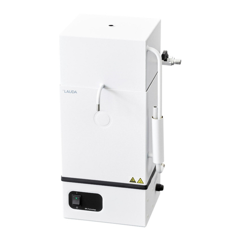
Lauda PD 2 R User manual

Operating Instructions
Puridest DistillationApparatus
PD 2 R, PD4 R, PD 8 R, PD 12R
DOMINIQUE DUTSCHER SAS

2 / 30 Puridest Distillation Apparatus 09/2020
DOMINIQUE DUTSCHER SAS

0
9
/2020
Puridest
Distillation Apparatus
3
/
30
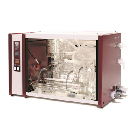
LAUDA Puridest Distillation Apparatus models PD 2 R, PD 4 R, PD 8 R and PD 12 R with storage tank produce highly-
pure, bacteria and pyrogen free distillate with a very low conductivity (approx 2.3 µS / cm at 25 °C). The distillate is in con-
formity with DABregulations and the regulations of many international pharmacopeia..
I II III IV
I Main switch
II Pilot lamp Clean
III Operation pilot lamp
IV Distillate withdrawal
Before installation, please check whether contents of package are in good order and complete.
Should younote any damages or have any reasons for complaint, please contact your supplier or directly.
LAUDA-GFL Gesellschaft für Labortechnik mbH
Schulze-Delitzsch-Str. 4+5
30938 Burgwedel - Deutschland
Telefon: +49(0)5139 9958 0
Fax: +49 (0)5139 995821
E-Mail: info@lauda-gfl.de
Internet: www.gfl.de
DOMINIQUE DUTSCHER SAS

4 / 30 Puridest Distillation Apparatus 09/2020
DOMINIQUE DUTSCHER SAS

0
9
/2020
Puridest
Distillation Apparatus
5
/
30
Content
Operating Instructions...................................................................................................................................................................1
1 Use oft he Distillation Apparatus..........................................................................................................................................7
Intended Use...................................................................................................................................................................................7
1.1
Improper Use..................................................................................................................................................................................7
1.2
2 Warranty................................................................................................................................................................................7
3 Before Initiation.....................................................................................................................................................................8
4 Set-up and Location of the Distillation Apparatus...............................................................................................................8
5 OperationVoltage.................................................................................................................................................................9
6 Water Connections................................................................................................................................................................9
Distillate withdrawal j................................................................................................................................................................10
6.1
Drain boiler k...............................................................................................................................................................................10
6.2
Cooling water outlet l...............................................................................................................................................................10
6.3
Tap water inlet m..........................................................................................................................................................................10
6.4
7 Initiation..............................................................................................................................................................................11
Before initialstarting....................................................................................................................................................................11
7.1
Initiation.........................................................................................................................................................................................11
7.2
8 FunctionalDescription.......................................................................................................................................................11
9 Maintenance,Service and Trouble Shooting......................................................................................................................12
Descaling........................................................................................................................................................................................12
9.1
Pilot LampClean..........................................................................................................................................................................12
9.2
9.2.1 Foam formation caused by polluted water in the boiler...............................................................................................12
9.2.2 Back water in the boiler......................................................................................................................................................13
Re-initiation after low water.......................................................................................................................................................13
9.3
10 Disposal of Old Units..........................................................................................................................................................13
11 TechnicalData....................................................................................................................................................................14
Distillation Apparatus Puridest models PD2 R, PD 4 R......................................................................................................14
11.1
Distillation Apparatus Puridest models PD8 R, PD 12R...................................................................................................15
11.2
12 Circuit Diagram..................................................................................................................................................................16
PD 2 R...........................................................................................................................................................................................16
12.1
PD 4 R...........................................................................................................................................................................................17
12.2
PD 8 R - version 230 V / 1 ~ for permanent connection to the mains...........................................................................17
12.3
PD 8 R / PD 12R - version 220 V / 3 ~ for permanent connection to the mains.......................................................18
12.4
PD 8 R / PD 12R – version 400 V / 3 ~ for permanent connection to the mains......................................................18
12.5
DOMINIQUE DUTSCHER SAS

6 / 30 Puridest Distillation Apparatus 09/2020
13 Connectionto the Mains....................................................................................................................................................19
Examples for connection to the mainssupply........................................................................................................................20
13.1
13.1.1 PD 2 Rand PD 4 R for 230 V for a mains supply of 220 V/ 3 ~ / PE / 50 / 60Hz........................................20
13.1.2 PD 2 R/ PD 4 R for 230 V for a mains supply of 400 V / 3 ~/ N / PE / 50 / 60Hz......................................20
13.1.3 PD 8 Rfor 230 V / 1~ for a mains supply of 220 V / 3~ / PE / 50/ 60 Hz.....................................................21
13.1.4 PD 8 Rfor 230 V / 1~ for a mains supply of 400 V / 3~ / N/ PE / 50 / 60 Hz..............................................21
13.1.5 PD 8 Rand PD 12 Rfor 220 V / 3 ~ for a mains supply of 220 V / 3 ~ / PE / 50/ 60 Hz............................22
13.1.6 PD 8 Rand PD 12 Rfor 220 V / 3 ~ for a mains supply of 220 V / 3 ~ / PE / 50/ 60 Hz............................22
13.1.7 PD 8 Rand PD 12 Rfor 400 V / 3 ~ for a mains supply of 400 V / 3 ~ / N / PE 50 / 60 Hz......................23
13.1.8 PD 8 Rand PD 12 Rfor 400 V / 3 ~ for a mains supply of 400 V / 3 ~ / N / PE 50 / 60 Hz......................23
14 List of spare parts................................................................................................................................................................24
15 Accessories andOptions.....................................................................................................................................................26
DOMINIQUE DUTSCHER SAS

0
9
/2020
Puridest
Distillation Apparatus
7
/
30
1 Use oft he Distillation Apparatus
Intended Use
1.1
In LAUDA Puridest Distillation Apparatus models PD 2 R, PD4 R, PD 8 Rand PD 12 Relectric heatingelements serve
to boil water andevaporate it. The steam is led through steam tubes into the storage tank where it condenses on a water-
cooled cooling coil. The produced distillate drips into the storage tank.The storage tank level is electronically monitored,
the Distillation Apparatus heating element(s) and cooling water supply will be switched off when the tank is full. Depending
on the model, the distillate quantity per hour ranges between 2litres (PD 2 R), 4litres (PD 4 R), 8litres (PD 8 R) and
12litres (PD 12R).
Dependingon the tap water quality, the produced distillate hasa conductivity ofapprox. 2.3 µS / cm at 25 °C.To feed
the Distillation Apparatus, preferably use tap water of drinking quality. Please also observe the information in chapters
16.2to 16.4 of these instructions on the possible use of filters and cartridges to pretreat the tapwater.
The Distillation Apparatus must be operated within the user's field of vision.
The information contained in these operating instructions must by all means beread and observed. Only
then a perfectoperation of the Distillation Apparatus can be guaranteed. The units mayonly be installed
and operated by persons who have made themselves familiar with these operating instructions.
Caution:
The accessible inner parts of the housing, that can be reached after lifting the outer lid get strongly heated
up during operation. These parts may only betouched after they have cooled down, or when wearing suita-
ble safety gloves.
Improper Use
1.2
LAUDA Puridest Distillation Apparatus, operated in a laboratory, are no Medical Devices. They fall neither under national
nor international Medical Device Directives andhave to be used and applied accordingly. The Distillation Apparatus must
not be used in potentiallyexplosive surroundings. The Distillation Apparatus must neither be set upnor operated in labora-
tory areas with aggressiveor corrosive ambient conditions
2 Warranty
For all laboratory apparatus and their accessories from LAUDA-GFL Gesellschaft für Labortechnik mbH, there is a war-
ranty claim, as well for spare parts, repairs and modifications, carriedout by LAUDA-GFL. In order to identify defective
units, we require both model and serial number on the nameplate, left-handside of the Distillation Apparatus and, if appli-
cable, a copyof the invoice.
DOMINIQUE DUTSCHER SAS

8 / 30 Puridest Distillation Apparatus 09/2020
3 Before Initiation
Important information are marked in boldletters in these instructions, safety indications are additionally markedby the fol-
lowing warning symbols and mandatory signs.
Read and observe the
operating instructions
Warning of hot liquids
and vapour Warning of hot surfaces
Warning of dangerous
electrical voltage General warning Before maintenance and repair
disconnect the unit all-pole from
the electrical mains (pull the plug
from the socket).
4 Set-up and Location of the Distillation Apparatus
Protect yourself and the unit during transport and setupby workingcarefully and avoid danger of e. g.
shifting or tilting the unit as well as risk of injury by liftingheavyloads.
Caution, Distillation Apparatus models PD 4 R(net weight 21.8 kg), PD 8 R(net weight 35.8 kg) and
PD 12 R (net weight 40.9 kg) must be lifted, carried and transported to the location by at leasttwo
persons. The Distillation Apparatus can be held between the four stands ofthe unit and lifted for setup.
The unit is suitable for both bench and wall mounting. It is only suitable for indoor use. Table-top setting-up on solid, even
and levelsurfaces only. Make sure to placethe unit only on a watertight, temperature-resistant,non-flammablesurface.
The locationmust providesufficient space as well as the necessary carrying capacity for the total weight ofthe unit (unit
weight as per technical data, chapter 11 of this manual, plus weight of the filling).
For setting-upon the wall, check the carrying capacity of the wall in connection with the total weightof the unit (appli-
ance plus water filling, see Technical Data).Make sure to check the on-site fixing elements in order to guarantee safe hold
of the Distillation Apparatus. The fixing material must be suitable for the substrate. Use only tested and proven fixing ma-
terial.
There are two keyholes for wall mounting at the back ofthe Distillation Apparatus. Place two fixing screws (not included in
the scopeof supply) in the wall in the distance of the two keyholes and nest the Distillation Apparatus onthe keyholes. The
unit is delivered without fixing material.
Model / Distance ofscrews
PD 2 R / 40cm
PD 4 R / 48cm
PD 8 R / 64cm
PD12R / 64cm
The unit is notsuitable for use in potentially explosive surroundings, e. g.during anaesthesia with inflammable gas orsteam
types!
DOMINIQUE DUTSCHER SAS

0
9
/2020
Puridest
Distillation Apparatus
9
/
30
5 Operation Voltage
The Distillation Apparatus must be connected tothe mains supply either by a correctly installedshock-
proof socket, or, with a fixed connection,to an on-site main switch. TheDistillation Apparatus is a pro-
tection class I electrical appliance, a connectionto the earth conductor (PE) must be ensured. For
informationon the required mains fuse please view Technical Data, chapter 11 of this manual.
The electrical connection must ensure an all-pole separation from themainsat any time. Shock-
proof sockets or main switches to separate the Distillation Apparatus fromthe mains must be installed
in such a wayas to ensure they can be clearly identified and are easily accessibleat any time.
The mains connection cable must not touch any hot surfaces of the unit. It may not lead underneath
the unit. The main switch (I) of the Distillation Apparatus must be off (position O). The voltage on the
nameplate (at the left-handside of the unit) must be identical to the mains voltage. If they are identical,
connect the unit to the mains. Please also refer to chapter 13of these operating instructions "Connec-
tion to the Mains".
6 Water Connections
All water connections of the Distillation Apparatus, except thedistillate withdrawal tap onthe front, are situated on the
right-hand sideof the unit.
Hoses for water inlet and outlet are not included in the standard scope ofsupply.
DOMINIQUE DUTSCHER SAS

10 / 30 Puridest Distillation Apparatus 09/2020
Distillate withdrawal j
6.1
Distillate is withdrawn from the unit through the black plastic tap on the frontof the unit. It can be opened in continuous
or interval positions. A laboratory hose with an inner diameter ofapprox. 15 mm can be connected to the tap, the hose
has to besecured from slipping off with a hose clip.
Caution:
The distillate leaves the Distillation Apparatus with a temperature ofmore than 50 °C.
Danger ofscaldings!
Drainboiler k
6.2
Connect a ½" hose to drain the boiler when cleaningthe unit and/or carrying out maintenance works.
Caution:
the water leaves the boiler of the Distillation Apparatus with atemperature of up to 100 °C.
Danger ofscaldings!
Cooling water outlet l
6.3
Connect a¾" temperature-resistant hose to the cooling water outlet. It may have a maximum length of approx. 1.5m. It
must be led into an open drainon a lower level and must have a slope on its complete length.
Make sure the cooling water can drain without back draughts.
Caution:
cooling water leaves the Distillation Apparatus with a temperature of up to 70 °C.
Danger ofscaldings!
Tap water inlet m
6.4
The tap water inlet supplies water to the Distillation Apparatus through a solenoid valve. The hose connection of the valve
must be connected with the water mains through a ½" pressure hose and a blockable water connection (⑤, handstop
valve).
It is absolutely essential to use hose clips to secure both hose connections!
DOMINIQUE DUTSCHER SAS

0
9
/2020
Puridest
Distillation Apparatus
11
/
30
7 Initiation
Before initial starting
7.1
Before initialstarting,the Distillation Apparatus has to be hand-filled with water. To do so, remove the outer and left-hand
inner lids (marked L) as well asthe deflector beneath the inner lid. Caution, when working on the deflector, make sure to
observe the correct position of the wireelectrode in the container. It may neither be bent nor come into contact with the
housing. The boiler must now be filled with water until the heating element(s) at the bottomof the container are below
water level. The deflector as well as the two individually marked inner lids must be re-assembled and safely nested on the
containers before initiation ofthe unit.
MarkingL Marking R
front of the front of the
left-hand inner lid right-hand inner lid
(boiler) (storage tank)
Initiation
7.2
To initiate the Distillation Apparatus after assembly of all power and water connec-
tions, open the hand-stop valveof the water mains supply ⑤and switch on the
main switch (I).The first few litres of produced distillate should not be used. Dis-
card the first two to three complete fillingsof distilled water inthe storage tank.
I II III
To switch off the unit for longer down-times, first switchthe main switch (I) to position O, and discon-
nect the unit from the mains. Close theon-site hand-stop valvesof the water supply, thenempty and dry
storage tank andboiler in order to avoid germ contamination.
8 Functional Description
LAUDA-GFLDistillation Apparatuses Puridest work automatically. After switching onthe Distillation Apparatus main
switch, the green pilot lamp in the main switch (I) as well as the right-hand, yellow operation pilot lamp (III)will light up.
The built-insolenoid valve opens. Water flows through the cooling coil in the storage tank and a mechanical water level
regulator that controls the water level in the boiler. Excess water that is not usedto evaporate,runs off through the cooling
water outlet. The heating elements are powered on and bring the water in the alembic to the boil. A thermostatic low water
cut-off protects the heatingelements from dry running. The produced steam is led through a steam tubeto the cooling
coil where it condenses and drips as distillate into the storage tank.
The water level inthe storage tank (right-hand container) is controlled through a wire electrode. Once the container is full,
the Distillation Apparatus will be switched off by an electronic controller. The solenoid valve interruptsthe cooling water
supply, the heating elements are switchedoff and the yellow pilot lamp (III) goes out. Distillate is withdrawn through the
black plastic tap at the front of the unit.
After withdrawal of distillate, the unit will be switchedon again automatically, so that thestorage tank is refilled.
Carbon dioxide is degassed through a vent on the top of the unit.
DOMINIQUE DUTSCHER SAS

12 / 30 Puridest Distillation Apparatus 09/2020
9 Maintenance, Service and Trouble Shooting
Caution:
Prior to maintenance and service on the unit let the Distillation Apparatus cool down!
Danger of burns!
Caution:
Before opening the Distillation Apparatus as well as prior to cleaning, separate the unit
from the mains supply! (Pull the plug or switchoff main switch).
Danger of electrical shock!
Descaling
9.1
Dependingon the degree of hardness of thetap water,the Distillation Apparatus must be cleaned regularly of scale for-
mations. First remove the outer and the left-handinner lids (L), then unscrew the deflector and remove it, too. Asuitable
descaling agent is amixtureof 10 % formic acid, 10% acetic acid and 80 % distilled water. Fill the solvent into the boiler
until it covers the topmost scale deposits andheat up to maximum approx. 70 °C.Make absolutely certain not to bring the
mixture toa boil. In order to do so, close the hand-stop valve ofthe water mains supply ⑤and switch on the Distillation
Apparatus until the temperature is reached. After approx. 30 minutes drain the solventand scale mixture through the
drain cock "drain boiler" ②andrinse the boiler thoroughly with water several times.
Commercial descaling agents, suitable for use with stainless steel, can also be used according to the manufacturer's in-
structions (e.g. rea-calc®of M/s CHEMOTEC GmbH, 63486 Bruchköbel, Germany). Never use any products con-
taining hydrochloric acid! These will lead to damages to heatingelement, boiler, temperature sensor and the ducts of the
screw connections. Restart the unit as described in chapter 7 Initiation.
After descalings, the first few litres of distillate should not be used as it might contain traces of evaporated descaling agent.
Discard the firsttwo to three complete fillings of distilled waterin the storage tank.
Pilot Lamp Clean
9.2
9.2.1 Foam formation caused by polluted water in the boiler
Depending on the degree of impurities inthe feed water as well as onthe grow-
ing contamination of the water in the boiler, causedby the distillation process,
the boiling water will foam up. Once the foam gets in contact with the electrode
in the boiler (L), an electronic impurity detector will switch offthe unit, and the
red pilot lamp Clean (II) will light up.
The boiler must now be emptied through the drain cock "drain boiler" ②and be
rinsed several times with clean water..
I II
The operational interruption "Clean" is reset byswitching the unit's main switchoff and then on again. The subsequent re-
initiation is to be carried out as described in chapter 7.
The "Cleaning" function's purpose is to exchange polluted water in the boiler against clean water.
DOMINIQUE DUTSCHER SAS

0
9
/2020
Puridest
Distillation Apparatus
13
/
30
9.2.2 Back waterin the boiler
If the water level inthe boiler rises up to the wireelectrode in the left-handcontainer (L), the electronic impurity detector
(A1 in the circuit diagram) switches the unit off and the red pilot lamp "Clean" (II) lights up. This means thatmore water
entered the unit than could flowoff. Possible causes are tubesoutside the unit that are not installed as described (see
chapter 6), orscale formations that cause a blockage in the water outlet tube insidethe unit. A defective quantity regula-
tor in the outlet of the solenoid valve (see cooling water requirement, chapter 11) might also cause more water to flow
into the unitthan can flow off.For troubleshooting purposes, an additional function drawing ofthe internalwater flow is
available onrequest.
Re-initiation after low water
9.3
To re-initiate, let the unit cool down and fill in water to coverthe heating elements
as described in chapter 7 Initiation.
The triggered lowwater cut-off must be reset. To do so, loosen the black capnut at
the bottom left-hand side of the Distillation Apparatus. Insidethe thread a small
white plastic pin can be seen that has to be gently pressed inside (e.g.with a pen)
until a clicking sound can beheard.
Only then switchthe unit back onagain.
The LAUDA-GFL Distillation Apparatus Puridest is made of first-class material. Nevertheless, the unitshould only be
subjected to mechanicalstrain withinsensible limits.
Make sure that no fluids come into contact with cable connections or the
electrical parts inside the unit!The powder-coated surfaces of the unit can be cleaned with mild detergents, if necessary.
Servicings, repairs or modifications must be carried out according to the General Engineering Standards by a competent
electrician.
Only original spare parts must be used. Always demand a detailed confirmation by the person in charge (company, date,
signature) onthe kind and volume of the tasks carried out.
10 Disposal of Old Units
LAUDA-GFL will take responsibility, within thescope of the legal directives, for an environmentally sound handlingand
disposal of all used LAUDA-GFL units as of the production year 1995 that are returned to us free of charge and will have
it materiallyrecycled. Before the unit is returned, a legally binding declaration must be provided from the sender confirm-
ing that the unit is free fromharmful and/or hazardous contaminations as well as from hazardous substances caused by the
previous use of the unit.
LAUDA-GFL laboratory apparatus are exclusively designed for industrial use and may not be disposed of through public
waste disposal authorities.
EAR Registration NumberWEEE-ID.NO.DE 67770231
DOMINIQUE DUTSCHER SAS

14 / 30 Puridest Distillation Apparatus 09/2020
11 Technical Data
Distillation Apparatus Puridest models PD 2 R, PD 4 R
11.1
PD 2 R PD 4 R
Exterior dimensions (W x D x H) 530 mm x 280 mm x 455 mm 615 mm x 320 mm x 495 mm
Storage tank 4 litres distillate 8 litres distillate
Distillation capacity 2 l / h distillate 4 l / h distillate
Distillate quality Mono distillate
approx. 2.3 µS / cm at 25 °C in conformity with
DAB, bacteria and pyrogen free, low gas content
Mono distillate
approx. 2.3 µS / cm at 25 °C in conformity with
DAB, bacteria and pyrogen free, low gas content
The conductivity of the distilled water is directly related to the chemical composition of the raw water. Components of the raw water having the same or a
lower evaporation point than water may deteriorate the conductivity.
Cooling water requirement 30 l / h 48 l / h
Low water cut-off Electromechanical temperature limiter, with capil-
lary tube sensor.
Switch-off temperature 135 °C / -15 K
Electromechanical temperature limiter, with capil-
lary tube sensor.
Switch-off temperature 135 °C / -15 K
Water pressure min. / max. > 3 bar / 7 bar
> 43.5 psi / 101.5 psi > 3 bar / 7 bar
> 43.5 psi / 101.5 psi
Electrical connection
Mains supply 230 V +/-10 %,
50 / 60 Hz, 1.5 kW
shock-proof plug
230 V +/-10 %,
50 / 60 Hz, 3.0 kW
shock-proof plug
Caution! Mains voltage deviations, even with the mentioned limits, influence the quantity of distillate produced.
Fuses
On-site fuse
Internal mains fuse 16 Amp.
10 Amp. T 16 Amp.
16 Amp. T
Protection class / - type I / IP20 I / IP20
Surrounding conditions Use only inside buildings (not in potentially explo-
siveareas). Use only inside buildings (not in potentially explo-
siveareas).
Height above MSL up to 2000 m MSL up to 2000 m MSL
Ambient temperature +10 °C to +40 °C +10 °C to +40 °C
Humidity max. 80 % rel. humidity to 31 °C, decreasing to
40 % rel. humidity at 40 °C max. 80 % rel. humidity to 31 °C, decreasing to
40 % rel. humidity at 40 °C
Net Weight 16.0 kg 21.8 kg
Weight with water filling 22.0 kg 32.4 kg
DOMINIQUE DUTSCHER SAS

0
9
/2020
Puridest
Distillation Apparatus
15
/
30
Distillation Apparatus Puridest models PD 8 R, PD 12 R
11.2
PD 8 R PD 12 R
Exterior dimensions (W x D x H) 780 mm x 405 mm x 575 mm 780 mm x 405 mm x 705 mm
Storage tank 16 litres distillate 24 litres distillate
Distillation capacity 8 l / h distillate 12 l / h distillate
Distillate quality Mono distillate
approx. 2.3 µS / cm at 25 °C in conformity with
DAB, bacteria and pyrogen free, low gas content
Mono distillate
approx. 2.3 µS / cm at 25 °C in conformity with
DAB, bacteria and pyrogen free, low gas content
The conductivity of the distilled water is directly related to the chemical composition of the raw water. Components of the raw water having the same or a
lower evaporation point than water may deteriorate the conductivity.
Cooling water requirement 72 l / h 198 l / h
Low water cut-off Electromechanical temperature limiter, with capillary
tube sensor.
Switch-off temperature 135 °C / -15 K
Electromechanical temperature limiter, with capil-
lary tube sensor.
Switch-off temperature 135 °C / -15 K
Water pressure min. / max. > 3 bar / 7 bar
> 43.5 psi / 101.5 psi > 3 bar / 7 bar
> 43.5 psi / 101.5 psi
Electrical connection
Mains supply
On-site fuse
230 V +/-10 %, 50 / 60 Hz, 6.0 kW
Connection box for permanent connection to the
mains Netzsicherung / on-site-fuse35 Amp.
220 V / 3 ~ / PE +/-10 %, 50 / 60 Hz, 9.0 kW
Mains connection cable for permanent connection
to the mains / on-site-fuse 3 x 25 Amp.
220 V / 3 ~ / PE +/-10 %, 50 / 60 Hz, 6.0 kW
Mains connection cable for permanent connection
to the mains / on-site-fuse 3 x 16 Amp.
400 V / 3 ~ / N / PE +/-10 %, 50 / 60 Hz, 9.0 kW
Mains connection cable for permanent connection
to the mains / on-site-fuse 3 x 16 Amp.
400 V / 3 ~ / N / PE +/-10 %, 50 / 60 Hz, 6.0 kW
Mains connection cable for permanent connection
to the mains / on-site-fuse 3 x 16 Amp.
Caution! Mains voltage deviations, even with the mentioned limits, influence the quantity of distillate produced.
Protection class / - type I / IP20 I / IP20
Surrounding conditions Use only inside buildings (not in potentially explosive
areas). Use only inside buildings (not in potentially explosive
areas).
Height above MSL up to 2000 m MSL up to2000 m MSL
Ambient temperature +10 °C to +40 °C +10 °C to +40 °C
Humidity max. 80 % rel. humidity to 31 °C, decreasing to 40
% rel. humidity at 40 °C max. 80 % rel. humidity to 31 °C, decreasing to 40
% rel. humidity at 40 °C
Net Weight 35.8 kg 40.9 kg
Weight with water filling 56.5 kg 70.4 kg
DOMINIQUE DUTSCHER SAS

16 / 30 Puridest Distillation Apparatus 09/2020
12 Circuit Diagram
A1 Electronic level switch
E1 Tubular heating element
E2 Tubular heating element
E3 Tubular heating element
H1 LED red "cleaning"
H2 LED yellow "operation"
Elektr. 1 Electrode "cleaning in boiler"
Elektr. 2 Electrode "water blocking"
Elektr. 3 Electrode "max. level storage tank"
F1 Mains fuse internal, Model PD 2R, 10 Amp. inert
Model PD 4 R, 15Amp. inert
F2 Mains fuse internal, Model PD 2R, 8 Amp. inert
Model PD 4 R, 15Amp. inert
F3 Low water cut-off (thermostat)
K1 Contactor
M Earth (housing)
S1 Main switch
Y1 Solenoidvalve
PD 2 R
12.1
DOMINIQUE DUTSCHER SAS

0
9
/2020
Puridest
Distillation Apparatus
17
/
30
PD 4 R
12.2
PD 8 R - version 230 V / 1 ~ for permanent connection to the mains
12.3
(seenameplate)
DOMINIQUE DUTSCHER SAS

18 / 30 Puridest Distillation Apparatus 09/2020
PD 8 R / PD 12 R - version 220 V / 3 ~ for permanent connection to the mains
12.4
(seenameplate)
PD 8 R / PD 12 R – version 400 V / 3 ~ for permanent connection to the mains
12.5
(seenameplate)
DOMINIQUE DUTSCHER SAS

0
9
/2020
Puridest
Distillation Apparatus
19
/
30
13 Connection to the Mains
The electrical connection must ensure an all-pole separation from the mainssupply. Installed assembly parts,such as
shock-proof sockets or mainswitches, must be installedso as to ensure clear identification and they must be within easy
reach in anemergency case. Distillation Apparatusmodels PD8 R and PD 12 Rmust have a permanent connection with
the mains. This may only be implemented through an on-site main switch or through a CEE plug in conformity with IEC
standard 60309-2 (seeexamples for connection to themains in chapter 13.1).
Colour decoding of the individual leads ofthe mains connectioncables for models PD 8 R and PD 12 R:
Colour decoding Mains supply
2
2
0
V / 3
~
/ PE 50 / 60Hz
Mains supply
400
V / 3
~
/
N /
PE
50 / 60
Hz
ge/gr
–
gelb/grün
PE (
Protective earth
)
PE (
Protective earth
)
bl
–
blue
N
sw
–
black
L1
L1
br
–
brown
L2
L2
gra
–
grey
L3
L3
Distillation Apparatuses can be suppliedin different versions for connectionto different mains supplies.
Models PD 2 Rand PD 4 R for connection to 230 V (see nameplate) can be connected to all mains supplies with 220 V
or 230 V.
Models PD 8 Rand PD 12 R for connection to 220 V / 3~ (see nameplate) can only be connected to mains supplies
with 220V / 3. ~ / PE.
Models PD 8 Rand PD 12 R for connection to 400 V / 3~ (see nameplate) can only be connected to mains supplies
with 400V / 3. ~ / N / PE.
Electrical fuses
Model
Power
Power consumption at mains voltage
*
Mains fuse (F2
–
F4)
PD 2
R
1.
5 kW
6.
5 A
at
230 V
1
0
Amp
PD 4
R
3
.
0
kW
13.
0 A
at
230
V
16
Amp
PD 8 R 6.0 kW
6.0 kW
6.0 kW
26.1A at 230 V
15.8A at 220 V / 3~ / PE
8.7 Aat 400 V / 3 ~/ N / PE
35Amp
16Amp
10Amp
PD 12 R 9.0 kW
9.0 kW
23.6A at 230 V / 3~ / PE
13.0A at 400 V / 3~ / N / PE
25Amp
16Amp
* see nameplate
DOMINIQUE DUTSCHER SAS

20 / 30 Puridest Distillation Apparatus 09/2020
Examples for connection to the mains supply
13.1
Components
B1 Shock-proofsocket (on-site)
B2 Shock-proof plug(mounted on the unit)
B3 CEE plug, not mounted, in conformity with IEC standard 60309-2
B4 Connection box, mounted on the unit
F2 Mains fuse (on-site)
F3 Mains fuse (on-site)
F4 Mains fuse (on-site)
S4 Main switch (on-site)
13.1.1 PD 2 R and PD 4 R for 230 V for a mains supply of 220 V / 3 ~ / PE /50 / 60 Hz
(seenameplate)
PD 2 R and PD 4R
Mains connection throughshock-proof plugCEE 7/7 (pre-
assembled), all-pole separable from the mains.
13.1.2 PD 2 R /PD 4 R for 230 V for a mains supply of 400 V / 3 ~ / N / PE / 50 / 60 Hz
(seenameplate)
PD 2 R and PD 4R
Mains connection throughshock-proof plugCEE 7/7 (pre-
assembled), all-pole separable from the mains.
DOMINIQUE DUTSCHER SAS
This manual suits for next models
3
Table of contents
Other Lauda Laboratory Equipment manuals
Popular Laboratory Equipment manuals by other brands

PerkinElmer
PerkinElmer IVIS Lumina S5 Hardware manual

Air Vent
Air Vent UV-C FiltAir Quick installation guide

3D Histech
3D Histech PANNORAMIC SCAN RX user guide

German pool
German pool OUB-108GY user manual

PerkinElmer
PerkinElmer Lambda 650 Hardware guide

Aqua Logic
Aqua Logic ALCUV-1 Installation & operating instructions

3D Histech
3D Histech TMA Grand Master 3.2 user guide

Exor
Exor JSPOU0P1 installation guide

PerkinElmer
PerkinElmer S20 Series installation guide

PerkinElmer
PerkinElmer FL 6500 installation instructions

Isotech
Isotech LIBRA 785 User maintenance manual/handbook

J.P. SELECTA
J.P. SELECTA CONTERM 19L instruction manual