Lauda Hydro H 4 User manual

Operating Instructions
Hydro Water Baths
H 4, H 8,H 16,H 22, H 24, H 41, H 8 A, H16 A

2 / 34 Hydro Water Baths 09/2020

0
9
/2020
Hydro
Water Bath
s
3
/
34
The product range of incubation and inactivation baths comprises eight models with six different sizes, ranging from 4 to 41
litres contents.Water Baths H 8 AandH 16 A are equipped with a circulation system, ensuring an optimum spatial temper-
ature distribution.
The outer housing is made ofelectrolytically galvanised and powder-coatedsheet steel; all other constructive parts of the
housing and the heating element are madeof stainless steel.
Three timer functions of the electronic controller permit regulation of the water temperature in the Water Bath. The con-
troller is equipped with an electronic performance check with visual and acoustic alarms in case of a malfunction. Further-
more, theWater Baths are protected in caseof dry running of the heating element.
Before installation, please check whether contents of package are in good order and complete.
Should younote any damages or have anyreasons for complaint, please contact your supplier or directly.
LAUDA-GFL Gesellschaft für Labortechnik mbH
Schulze-Delitzsch-Str. 4+5
30938 Burgwedel - Germany
Telefon: +49(0)5139 9958 0
Fax: +49 (0)5139 995821
E-Mail: info@lauda-gfl.de
Internet: www.GFL.de

4 / 34 Hydro Water Baths 09/2020

0
9
/2020
Hydro
Water Bath
s
5
/
34
Contents
1 Use of the Water Bath...........................................................................................................................................................7
Intended Use...................................................................................................................................................................................7
1.1
Improper Use..................................................................................................................................................................................7
1.2
2 Warranty................................................................................................................................................................................7
3 Before Installation / Initiation...............................................................................................................................................8
4 Transport,Setup and Location ofthe Water Baths...............................................................................................................8
5 Operating Voltage.................................................................................................................................................................9
6 Filling water into the Water Bath..........................................................................................................................................9
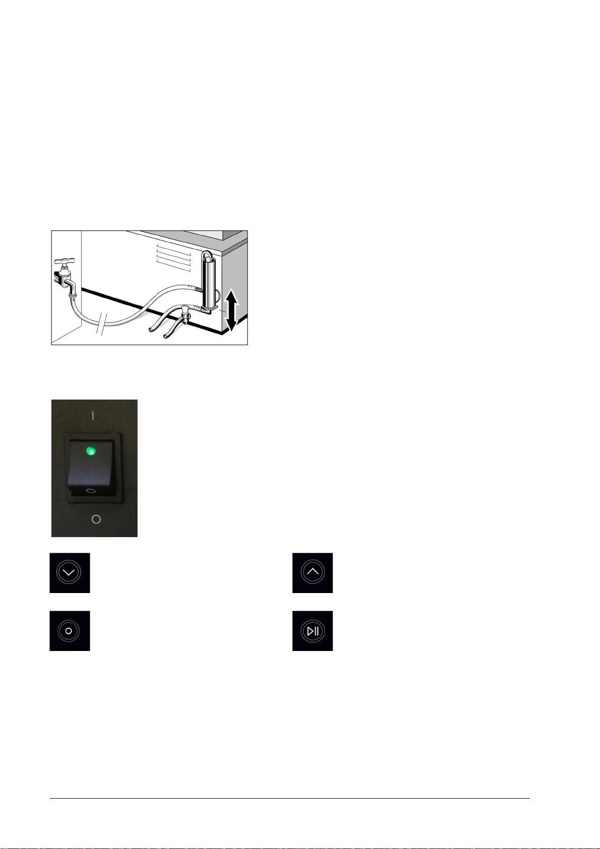
7 Adjustable Water Level Regulator (AccessoryOrder-No. A000024)............................................................................ 10
8 FunctionalDescriptionandInitiation.................................................................................................................................10
Main Menu....................................................................................................................................................................................11
8.1
8.1.1 Setting the required temperature....................................................................................................................................12
8.1.2 Setting the switch-on delay..............................................................................................................................................12
8.1.3 Setting the operation time of Water Bathheating........................................................................................................13
Switching to menu basic settings...............................................................................................................................................13
8.2
8.2.1 Limitation ofthe max. or min. possibletemperature set points in two separate input windows............................15
8.2.2 Setting the trigger points for over- and under-temperature alarms in two separate input windows...................15
8.2.3 Switching between temperature display °C and °F.......................................................................................................16
8.2.4 Start options of the process duration..............................................................................................................................17
8.2.5 Adjusting the actual temperature at a certain set point temperature........................................................................17
8.2.6 Switching back to the main menu....................................................................................................................................18
Display of current process data.................................................................................................................................................18
8.3
Function control with visual and acoustic alarms....................................................................................................................19
8.4
9 Water Circulation (onlyWater Baths models H 8A und Typ H16 A)............................................................................20
10 Maintenance and Support..................................................................................................................................................20
Exchangingthe internal unit fuses.............................................................................................................................................20
10.1
Low water cut-off.........................................................................................................................................................................21
10.2
Under-temperature alarm..........................................................................................................................................................21
10.3
Over-temperature alarm............................................................................................................................................................22
10.4
Temperature sensor is interrupted............................................................................................................................................22
10.5
Temperature sensor has short circuit........................................................................................................................................22
10.6
RemovingLime Deposits, Cleaning and Maintenance..........................................................................................................23
10.7
10.7.1 Descaling..............................................................................................................................................................................23
10.7.2 Cleaning and Maintenance................................................................................................................................................23
10.7.3 Decontamination.................................................................................................................................................................23

6 / 34 Hydro Water Baths 09/2020
11 Disposal of Old Units..........................................................................................................................................................24
12 TechnicalData.....................................................................................................................................................................25
13 Circuit diagram....................................................................................................................................................................26
14 Examples for connection tothe mains supply....................................................................................................................27
Electrical fuses.............................................................................................................................................................................27
14.1
Examples for connection to the mains....................................................................................................................................28
14.2
15 Spare Parts List...................................................................................................................................................................29
16 Accessories..........................................................................................................................................................................31

0
9
/2020
Hydro
Water Bath
s
7
/
34
1 Use of the Water Bath
Intended Use
1.1
LAUDA Hydro Water Baths are used toheat up tap water in a temperature range of approx. 5 K above ambi-
ent to 100°C (models H 4 to H 41) and from approx. 10 K above ambient to 100°C (models H 8 A and H
16 A)for temperature-controlled warming of different media in laboratory vessels of different shapes.
The information contained in these operating instructions must by all means beread and observed. Only then cana per-
fect operation ofthe Water Bath be guaranteed. The units may only be installed and operated by persons who have made
themselves familiar with these operating instructions.
Caution:
Hot surfaces at temperaturesabove 50 °C. Danger of burns, and danger of scaldings through
steam released when opening the lidof the Water Bath. It is recommended to wear suitable
safety gloves
Caution:
Increased risk of injury! Uncontrolled closing of theWater Bath lidcarries a high risk of injury. Protect
yourself by working carefully onWater Baths with open lid.
Improper Use
1.2
Use the Water Bath with tap water only. Other media, e. g.oils or acids, will lead to damages and, possibly, total unit fail-
ure. Neitheraggressive nor corrosive waters may be used as athermostating liquid.
The Water Bath may not be used in laboratory areas with aggressive or corrosive ambient conditions. It is not permissible
to heat up or vaporise aggressive media,e. g. hydrochloric acid, in the unit itself or in its vicinity.
The temperature work must not create an explosive atmosphere in the vicinityof the unit.
The Water Bath may not be operated in potentially explosive surroundings.
LAUDA Hydro Water Baths are not suitable for direct temperature work of foodstuffs, beverages and tobacco or for
medical-technical and pharmaceutical products. Direct temperature work means unprotected contact of thesubstances
with the Water Bath filling.
LAUDA Hydro Water Baths,operated ina laboratory, are no MedicalDevices. Theyneither fall under national nor inter-
national MedicalDevice Directives nor have to be used and applied accordingly.
2 Warranty
For all laboratory apparatus and their accessories fromLAUDA-GFL Gesellschaft für Labortechnik mbH, there is a war-
ranty claim, as well for spare parts, repairs and modifications, carriedout by LAUDA-GFL. In order to identify defective
units, we require both model and serial number on the nameplate at the back, left-handside of the Water Bath and, if
applicable, a copy of the invoice.

8 / 34 Hydro Water Baths 09/2020
3 Before Installation / Initiation
The information given in the present manual must by all means be carefullyread and observed. Only then cana perfect
functioning ofthe Shaking Water Bath be guaranteed.
Safety precautions are additionally markedwith the followingsymbols.
Read and observe the
operating instructions
Warning of hot liquids
and vapour Warning of
hot surfaces Warning of hand
injuries
Warning of
dangerous
electrical voltage
General
warning Before maintenance and repair
disconnect the unit all-pole from
the electrical mains (pull the plug
from the socket).
4 Transport, Setup and Location ofthe Water Baths
Protect yourself and the unit during transport and setupby working carefully and avoid danger of e. g.
shifting or tilting the unit as well as risk of injury by liftingheavyloads.
Caution, Water Bath TypH 41 has a net weight of 21.2kg and must be lifted, carried and transported to the location by
at least two persons.
The Water Bath can be held between the four stands of the unit and lifted for setup. Place on solid, even and level surfaces
inside buildings only. Makesure to place the unit only on a watertight, temperature-resistant, non-flammable surface. The
location must provide sufficient space as well as the necessary carrying capacity for the unit (unit weight as per technical
data, chapter 12 ofthis manual plus weightof the filling.

0
9
/2020
Hydro
Water Bath
s
9
/
34
5 Operating Voltage
The Water Bath must be connected to a correctly installed shock-proofsocket. TheWater Bath
is a protection class I electrical appliance, a connection to theearth conductor (PE) must be
ensured. For informationon the required mains fuse please view Technical Data, chapter 12 of
this manual.Further reference for connection to the mains can be found in chapter 14 of this
manual.
The electrical connection must ensure an all-pole separation from the mains at any time. The mains
connection cable must nottouch any hotsurfaces of the unit. It may not lead underneaththe unit.
The main switch of the Water Bath must beoff (position O).The voltage on the nameplate (at the
back of the unit) must be identical to the mains voltage. If they are identical, connect the unit to the
mains.
6 Filling water into the Water Bath
Use the Water Bath only with tap water. Even stainless steel will corrode when used improperly. Use nei-
ther ferruginous nor chlorous water, in order to prevent rust formation and pitting. Using distilled or deion-
ised water will also ultimately lead to corrosion in the Water Bath and must, therefore, be avoided.
Media, such as oil, acid, or other additives, not approved byLAUDA-GFL, to prevent bacteria contamina-
tion (chlorine or copper sulphate), may lead to damages to theWater Bath basin, the screw connections of the ducts and
the heating element. Such damages are not covered by guarantee.
Before initiation, the Water Bath must be filled with water. For maximum filling quantities please refer to theTechnical
Data, chapter 12 of this manual. Make sure that the drain cock at the back of the unit is locked (handle must be ina 90°
angle to the drain cock).Open the lid of the unit and fill in water at least upto the marking "min" (approx. 50 mm above
the perforated floor) and not exceeding the marking "max" (approx. 50mm below the upper bath rim).

10 / 34 Hydro Water Baths 09/2020
7 Adjustable Water Level Regulator (Accessory Order-No. A000024)
The adjustable water regulator at the back of the Water Bathserves to level out the loss of water due to evaporation during
operation, thus maintaining the set water level. Furthermore, the adjustable water regulator allows theWater Bath to be
operated attemperatures below ambient, with aminimum of approx. 3 K above tap watertemperature.
Before initiation, the water regulator must be connected to thewater mains.The upper hose connection of the water
regulator is the water supply. Using a laboratory hose with an inner diameter of max 9 mm, connect this to the water
mains. The lower hose connection is the overflow of the waterregulator. Connect a laboratory hose (inner diameter of max
9 mm) and leadit into a drainon a lower level, ensuring free flow of the water without it being banked up.
Secure all hose connections with hose clips.
The required water level can be adjusted with the outlet tube ofthe
water regulator. First loosen thescrew connection of the outlet tube,
using a spanner GW 27. Set the required water level by pulling out or
pushing in the tube in the regulator. Then retighten thescrew con-
nection. Nowopen the tap of the mains supply slightly and fill water
into theWater Bath, as described in chapter 6.
8 Functional Description and Initiation
The electronic regulator controls the water temperature ofthe Water Bath. Three timer functions
permit switch-on delay as well as setting the duration ofthe operation time. A high-contrast 3.5"
TFT displayshows all set points and operational values. These can be controlled with four mem-
brane keys, situated to the rightof the display. The controller isequipped with an electronicmoni-
toring function with visual and acoustic alarms in case of a malfunction. Additionally, the Water
Bath is protected from overheating through running dry by a low water cut-offthat is also moni-
tored by the function control of the regulator. After switching on the mainswitch of the Water
Bath, the green pilot lamp inthe switch will light up.The displayfirst shows thestartup screen, and
then the mainmenu. The four membrane keys to the right of the display allow access to all menu
functions, setting and confirming process values.
Key ①to reduce process values and to switch
between menu functions. Key ②to increase process values and to switch
between menu functions.
Key ③to open and close input windows, con-
firm set process values andto leave sub-
menus.
Key ④to startand stop processes.

0
9
/2020
Hydro
Water Bath
s
11
/
34
Main Menu
8.1
The Water Bath is started in the main menu after checking the set points. Sub-functions of the main menu permit set-
ting and saving the values for temperature, switch-on delay and operation time. The current set points are shown below
the symbols ofthe relative function and remain saved after switching theWater Bath off. Furthermore, the main menu
permits access to the basic settings of theregulator. The bottomline of the following input windows provide information
on the tasks assigned to keys ①,②and③.
Keys ①and②permit to move in the menu. The current function is marked in black
and can be opened with key ③. Ifthe savedset points below the functionsymbols are in
conformity with your process requirements, the Water Bath can be started by pressing
key④(keep pressed for 3seconds) andswitched offagain by pressing key ④(shortly).
Key
①
Key
②
Key
③
Key
④
Set temperature
with currentlysaved set point
(see 8.1.1)
Switch-on delay
with currentlysaved set point
(see 8.1.2)
Operation time
with currentlysaved set point and pre-
set timer functions
(see
8.1.3)
Basic settings
(see 8.2)

12 / 34 Hydro Water Baths 09/2020
8.1.1 Setting the required temperature
In this input window, the required temperatureof a process is set. The temperature can be set between 10
°C and 100 °C.The setting range of therequired temperature can be limited withinthe values pre-set in
the basic setting menu (see 8.2.1) and is displayed in either °Cor °F (see 8.2.3). Set point 100 °C is a
pure boiling mode. The Water Bath's heating element is supplied with energy constantly.
Use keys ①and ②to set the required temperature value, confirm with key ③and
return to the main menu.The set point is now displayed beneath the temperature sym-
bol in the main menu.
Key
①
Key
②
Key
③
Factorysetting 50.0 °C
8.1.2 Setting the switch-on delay
In the opened input window,the value t in hours and minutes (h:min) for delayed switch-on of the heat-
ing can be pre-set. The delay can be set between 0:00 (operation without delay) and max
999:59 h:min.
Set the requiredtime value with keys ①and ②, then confirm with key ③andreturn to
the main menu. The set delay will be displayed beneath the symbol of the switch-on
delay in the main menu.
Key
①
Key
②
Key
③
Factorysetting 0:00h:min

0
9
/2020
Hydro
Water Bath
s
13
/
34
8.1.3 Setting the operation time of Water Bath heating
In this input window, the operationtime t in hours and minutes (h:min) or continuous operation can be
set. The operation time is to be set from∞(continuous operation) through 0:01 to max. 999:59 h:min.
The pre-set starting option of the timer, set in the menu "basicsettings" (see 8.2.4), is displayedsymbol-
ically beneath the functionsymbol for operation time.
Start of operationtime right afterexpiry ofthe delay.
Delayed start of operation time after expiry of the delay, approx. 0.1K
before reaching the set temperature.
Use keys ①and ②to move in the menu. The current function is marked in black, key ③opens the input window to define
the required pre-set value.
Key
①
Key
②
Key
③
Factorysetting: Start of operation time right after expiry of delay, operation time ∞
Switching to menu basic settings
8.2
In the menu basic settings, pre-sets for temperature, over- and under-temperature alarms as well as
operationtime can be defined. Furthermore, the menu offers atemperature calibration.
Use keys ①and ②to move in the menu. The current function is marked in black, key ③
opens the input window to define the required pre-set value.
Key
①
Key
②
Key
③

14 / 34 Hydro Water Baths 09/2020
Limitation of maximum possible tem-
perature that can be pre-set
(see
8.2.1)
Limitation of minimum possible tem-
perature that can be pre-set
(see
8.2.1)
Setting trigger point of over-
temperature alarm
(see
8.2.2)
Setting trigger point of under-
temperature alarm
(see
8.2.2)
Switching between temperature display
°C und °F
(see
8.2.3)
Switching between start options of the
process duration
(see
8.2.4)
Adjusting the actual temperature
(see 8.2.5) Switching back to main menu
(see 8.2.6)

0
9
/2020
Hydro
Water Bath
s
15
/
34
8.2.1 Limitation of the max. or min. possible temperature set points intwo separate input windows
The operatingtemperature ofWater Baths models H 4 toH 41 is between approx. 5 K
above ambient, from models H 8 A andH 16 A approx. 10 K above ambient,to 100 °C
(boilingpoint). Both minimum and maximumtemperature set points can be limited in two
input windows.
The maximumset point can be defined between 10.9 °C and 100 °C, the minimum set
point between 10.0 °C and 99.1 °C.The values of both functions are interlocked. The
maximum limitation of the set temperature cannot beset lower than the minimum limi-
tation and vice versa. Therefore, the temperature can be set and limited between 10 °C
and 100°C.
Use keys ①and ②to set the required temperatures, confirm with key ③andreturn to the displayof menu basic settings.
Key
①
Key
②
Key
③
Factorysetting maximum possible temperatureset point 100 °C
Factorysetting minimum possibletemperature set point 10.0°C
8.2.2 Setting the triggerpoints for over- and under-temperature alarms in two separate input windows
After theset temperature of a current process has been reached for the first time, the
alarm functions for over- and under-temperature are activated. If the actual temperature
then exceeds or falls below the temperatures determined in the input windows, the current
process is interrupted, and an acoustic and visual alarm is triggered.
The switch-on point for theover-temperature alarm can be set between 0.0 K and +10
K above theset point temperature. The switch-on point for theunder-temperature
alarm can be set between 0.0K and -10 K below the set pointtemperature. Only if
process-related and absolutely unavoidable, should the value for the under-temperature
alarm be set lower than -4.0 K and theover-temperature alarm to values lower than
+2.0 K.
Use keys ①and ②to set the trigger points of the alarm functions, confirm with key ③and return to the displayof the
menu basicsettings.
Key
①
Key
②
Key
③
Factorysetting over-temperature alarm +4.0 K
Factorysetting under-temperature alarm -9.0K

16 / 34 Hydro Water Baths 09/2020
8.2.3 Switching between temperaturedisplay °C and °F
All temperature values in the display can either be displayed in °C or °F.
Use keys ①and ②to switch between °C und °F. The chosen temperature unit is marked in black andcan be
confirmed with key ③. The display returns to the menu basicsettings.
Key
①
Key
②
Key
③
Factorysetting °C

0
9
/2020
Hydro
Water Bath
s
17
/
34
8.2.4 Start options of the process duration
The set process durationstarts eitherafter expiry of the pre-set delay time (upper line), or after expiry of the
delay time approx. 0.1 K before reaching the pre-set temperature.
Use keys ①and ②to switch between the two start options. The chosen option is marked
in black and is to confirmedwith key ③. The display returns to the menu basic settings.
The symbolof the selectedstart option is alwaysshown together with the symbolof the
operationtime in the input anddisplay windows.
Key
①
Key
②
Key
③
Factorysetting startright after expiry of pre-set delay
8.2.5 Adjusting the actual temperature at a certain set point temperature
The user can adjust the actual temperature at a certain process-dependentset point temperature. To do this,
compare the actual temperatureshownon the display, after two hours operation with the Water Bath interior
covered, withthe displayed value of an external, calibrated thermometer in order to determine the tempera-
ture difference of the measured values. This difference must then be implemented in the input window of the
adjusting function.
Example, after a process duration of twohours at a temperature of 50 °C
Temperature value in the display
50,0 °C
Value measured with extern
al thermometer
49,2 °C
Differenceto the externallymeasured temperature
-
0,8
K
In this case, the value in the input window of the adjusting function must be changed
by -0.8 K from +3.4 K to +2.6 K in order to adjust both temperature values.
Set the altered temperature value with keys ①and②and confirm with key ③. The display returns to the menu basic
settings.
The changed value should be re-confirmed by a second,ensuing temperature measurement.
Key
①
Key
②
Key
③
A factory adjustment was carried out at atemperature of 50 °C.

18 / 34 Hydro Water Baths 09/2020
8.2.6 Switching backto the main menu
Use key ③toswitch back from the menu basic settings to the main menu.
Key
③
Display of current processdata
8.3
After starting the Water Bath with the pre-set process data, press key ④
(hold for 3 seconds) toopen a display field showing the current process
data: set and actual valuesof temperature in °C or °F, switch-on delay and
operationtime with their relative function symbols. Expiry of apre-set
process time is indicated by an acoustic signal which is to be confirmed with
key③to be switched off. By pressing key ④(shortly) all temperature
processesare ultimately terminated, the displayof the current process data
switches off and returns to the main menu.
Key
③
Key
④
The upper line shows the actualtemperature. The depicted thermal energy symbolto the leftof
the temperature value shows the energy supply to the heatingelement. The actual temperature
in the example is 89.6 °C.
Display ofthe set temperature, in the example 100 °C
Remainingrun times of delayand/or operation times (∞whenin continuous operation) with
their relative function symbols. A flashing function symbolsignals running-down times of process
times, parallel to the reducingtime value. In the example,the process willrun for another 3:35
h:min andstarted without switch-on delay.
Pre-set set point of the delay time. The example shows 0:00 h:min, immediate start without
switch-on delay.
Pre-set set point of the operation time. In the example 3:35 h:min.
Caution,
observe by all means. To switch off the unit for longer down-times first switch the main switch to position O, then
disconnect the unit fromthe mains. The Water Bath must be emptied, and the interior dried in
order to avoid germ contamination.

0
9
/2020
Hydro
Water Bath
s
19
/
34
Function control with visual and acoustic alarms
8.4
The temperature controller is equipped with an electronic function control. The following features are supervised: the
switching contact of the low water cut-off, the pre-set values for over-and under-temperature alarms (see chapter
8.2.2), and the temperature sensor B1 (see chapter 13) for short circuit and interruption. In case of a malfunction
acoustic and visual alarms willbe induced. Visually, the kindof malfunction will be coded on the display, alternating with the
current operation data, pendingthe user's confirmation (ill.1 and 2).
ill
1
ill
2
ill
3
The current process stops,heating as well as running time functions. After confirming the displayed malfunction withkey
③, the acoustic alarmis switched offand the visual indication (ill. 1) of the kind of malfunction disappears. The malfunc-
tion, markedin yellow and with a"caution"symbol, as well asthe code number remain shown in the displayof on-going
process data (see ill. 3). The blue symbol indicates the necessity of consulting the operating instructions. Error codes 001,
002 and003 must be reset by pressing key ④(shortly), error codes 004and 005 must be reset byswitching off the
Water Bath's main switch. Only after a technical analysisof the malfunction should the terminated process be restarted.
Key
③
Key
④
Error code displayed by the function control in case of a malfunction
Code 001 Low water cut-off has been triggered and must be reset.
Code 002 Under-temperature alarm after the actual temperature fallingbelow the pre-set value
(see chapter 8.2.2).
Code 003 Over-temperature alarm after the actual temperature exceeding the pre-set value (see chapter 8.2.2).
Code 004 Temperaturesensor is interrupted.
Code 005 Temperaturesensor has short circuit.
Caution For further information and support on maintenance of a Water Bath after anerror
report of the function control please view chapters 10.2to 10.6 of these operating instructions.

20 / 34 Hydro Water Baths 09/2020
9 Water Circulation (only Water Baths models H 8 A und Typ H 16 A)
The circulation system ensures an optimized temperature distri-
bution throughoutthe whole Water Bath. It isoperated by an
electric motor with stirring magnet, flanged to the Water Bath
basin, thattransmits its torque to a PTFE-coated stirrer. The
stirrer draws the water to the middle of the basin andthen moves
it back to all sides. The electric motor of the water circulation is
activated via the main switch.
10 Maintenance and Support
Caution! Prior to maintenance and cleaning let the Water Bathcool down!
If required, the water in theWater Bath can be drained through the drain cock at
the backof the Water Bath.
Caution: Danger of burns!
Make sure to prevent liquids coming into contact with cable connections or the
inside of theelectrical appliance. Except when descaling the unit (see chapter 10.7)
disconnect the unit fromthe mains by pulling the plug, thus separating the Water
Bath all-pole from the mains. Repairs of theelectrical system may only be carried
out by a trained electrician.
Exchanging the internal unit fuses
10.1
In direct proximity of the mains connection cable's screw joint, the mains fuses F1 and F2
(see chapter 13) are fixed on a fuse holder in the insideof the Water Bath. In order to
check and to exchange the fuses, the bottom plate of the Water Bath must be removed.
The fuses may only be exchanged against fuses of identical specifications. For information
on the fuses used please view the label next tothe fuses as wellas the spare parts list (see
chapter 15).
In addition to the following chapters 10.2to 10.6 please observe by all means the information in these
operating instructions, chapter 8.4, on resetting alarmreportsof the function control.
This manual suits for next models
6
Table of contents
Other Lauda Laboratory Equipment manuals
Popular Laboratory Equipment manuals by other brands

RayTek
RayTek ThermoView Pi20 operating instructions

Zeiss
Zeiss Corona process user manual

Rohde & Schwarz
Rohde & Schwarz EZ-17 user manual

Hettich
Hettich ROTO SILENTA 630 RS operating instructions

Global Focus
Global Focus Silencer JET Series Service manual

Xsential
Xsential QUAD-RO Installation and maintenance manual

WPI
WPI UltraPath 2 System guide

Planet Networking & Communication
Planet Networking & Communication POE-164 user manual

Leonton
Leonton GINJ-0201-EBT-T Hardware user manual

Cannon
Cannon CT-2000 manual

Covaris
Covaris M220 user manual

Barnstead Thermolyne Corporation
Barnstead Thermolyne Corporation 494 Series Operation manual and parts list