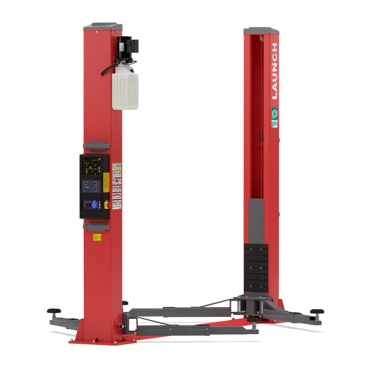
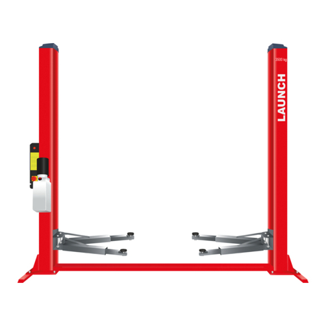
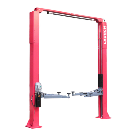
Launch TLT235SB User manual

LAUNCH Installation Instruction for Economical Symmetric Floor-plate 2-post Lift
i
Table of contents
1. Precaution………………………………………………1
2. Structure and working Principle.………………2
2.1 Structure Schematic Diagram…….……………………2
2.2 Main Structure and Principle of the Equipment...……3
3 Tools for installation and adjustment………………4
4. Unpacking…………………………………………….4
5. Installation…………….………………………………4
5.1 Important notice……………………………………4
5.2 Installation Procedure…………………………………4
5.2.1 Selecting installation site …………………………...4
5.2.2 Base plate layout……………………………………...5
5.2.3 Install the powerside column………………………….5
5.2.4 Install the floor plate…….………………………………6
5.2.5 Install the offside column………………………………6
5.2.6 Install and adjust the balancing steel cables………7
5.2.7 Install the power unit………………….…..………..…7
5.2.8 Connecting the power supply…………………………7
5.2.9 Connecting the hydraulic lines………………………...8
5.2.10 Install the swing arm and guardrail…………………..9
5.2.11 Adjust the steel chain…………………………………6
5.2.12 Install the floor plate cover…………………………9
6. Lift Adjustment……….……………………………….10
6.1 Preparation before adjustment……………………10
6.2 Adjustment procedure…………………………………10
7. List of the lift components………………………11
Diagram of the electrical system TLT235/TLT240SB...16
Diagram of the hydraulic system TLT235/TLT240SB…17

LAUNCH Installation Instruction for Economical Symmetric Floor-plate 2-post Lift
1
1 Precaution
Warning
zThis manual is an essential integral part of this
equipment. Please read it carefully.
zProperly keep this manual for use during the
maintenance.
zThis lift is only used for its clearly designated purpose.
Never use it for other purposes.
zThe manufacturer is not responsible for any damage
or injury caused by improper use or use for other
purposes.
Precautions for the Installation
and Adjustment:
zBefore the installation and adjustment, carefully read
this manual and the user’s manual. Without the
permission of the manufacturer or not followingthe
requirement of the manual, any changes on the
machine parts and its usagemay cause direct or
indirect damage to the machineand injury on
operators.
zTo do the installation and adjustment, the personnel
must have certain electrical knowledge.
zThe operators must undergospecial training and are
qualified.
zFix and install the lift on the stable concreted floor.
zThe lift shall be installed in a sufficient space so that
the operation is not restricted.
zDon’t expose the lift to the extreme temperatureand
humidity environment. Avoidinstallation beside the
heating equipment, water tap, air humidifier or stove.
zDon’t install the lift in front of the window wherethe
sunlight can shine directly. When it’s unavoidable, use
curtain to shield the sunlight.
zThe manufacturer reserves the right to make design
changes or add improvements to its product line
without notice.
zBefore installation, carefullycheck the packing list of
lift. In case of any question, please contact the
distributor or LAUNCH immediately.

LAUNCH Installation Instruction for Economical Symmetric Floor-plate 2-post Lift
2
2. Structure and working
principles
2.1 Structure schematic diagram
TLT235SB(TLT240SB)the Floor-plate two-post lift
structure is shown below (Figure 1, Figure2):
SWING ARM
FLOOR PLATE
CARRIAGE
3370
min110
LIFTING PAD
POWERSIDE COLUMN
2750
2780
800
LOWERING HANDLE
START BUTTON
POWER UNIT
OFFSIDE COLUMN
Figure 1

LAUNCH Installation Instruction for Economical Symmetric Floor-plate 2-post Lift
3
2700
186
986
300
300
2586
3370
1200
R800
Figure 2
2.2 Main structure and principle
of the equipment
zLifting mechanism: Each of the two columns has
one hydraulic cylinder respectively. When the
power unit works, the hydraulic oil gets into the
lower chamber of the cylinder, forcing the piston
rod moves upward. At this time, the carriage
moves upward through the chain.
zSupporting mechanism: When the vehicle enters
into the working area, adjust the position of two-
stage telescopic swing arms to make the lifting
pad near the correct lifting point of the vehicle,
and then adjust the screw height below the pad
to adapt to different heights ofvehicle chassis.
zBalancing mechanism: To keep the balance
during the lifting and lowering process, the lift
uses two steel cables to interconnect two
carriages, forcing the carriages to rise and
descend synchronously. If the carriages and
swing arms are not on the same level, adjust the
screw at the end of the steel cable, making the
swing arms at the same level (equal position
from the floor). At this time, the steel cables
must be adjusted tightly with equal tension,
otherwise the equalization can’t be ensured.
zManual safety locking system: the safety locking
plates are installed on the two carriages and the
toothed bar plate is welded on the internal wall
of the column. During the lifting of the carriage,
Passing width 2486

LAUNCH Installation Instruction for Economical Symmetric Floor-plate 2-post Lift
4
the safety locking plate goes up against on the
toothed bar plate by the tension of spring. When
the carriage stops, the safety locking plate
opens and then is engaged in the toothed bar
slot to ensure the carriage will not go down;
when the lowering operation is required, just
raise the carriage upward a little to loosen the
safety locking plate from the toothed bar slot,
and then manually pull the steel wire rope so as
to jack up the safety locking plate by sliding
plate, so the safety locking is released so that
the carriage can be lowered down. Because the
manual safety locking systems are installed on
the two carriages, double safety protection can
be provided; therefore, to disengage the safety
locking, the steel rope on the two carriages shall
be respectively pulled.
zTo prevent the vehicle slip, the swing arm is
installed with positioning mechanism, making
the swing arm capable of automatic locking
during operation.
zSafety scope: The safety lock mechanism is
effective from the height of lifting pad 450mm to
1900mm.
3. Tools for installation
and adjustment
To ensure proper installationand adjustment, please
prepare the following tools:
Tool Model
Leveling instrument Carpentry type
Chalk line Min 4.5m
Hammer 1.5kg
Medium crescent wrench 40mm
Open-end wrench set 11mm-23mm
Ratchet socket set
Flat screwdriver 150mm
Rotary hammer drill 20mm
Concrete drill-bit ¢19mm
4. Unpacking
zOpen the packing box; remove the packing materials
and inspect the lift for any sign of shipment damage.
Check by packing list to see if the main parts and
accessories are complete.
zKeep the packing materials away from the children to
avoid danger; if the packing materials cause the
pollution, they shall be treatedproperly.
5. Installation
5.1 Important notice
zThe wrong installation will cause the lift damage or
personal injury. The manufacturer will not undertake
any responsibilities for any damage caused due to
incorrect installation and usage of this equipment,
whether directly or indirectly.
zThe correct installation location shall be “horizontal”
floor to ensure the horizontal lifting. The slightly slope
floor can be corrected by proper shimming. Any big
slope will affect the height of the lifting pad when at the
bottom or the horizontal lifting. If the floor is of
questionable slope, consider a visual inspection, or
pour a new horizontal concrete slab if possible. In
short, under the optimum horizontal lifting status, the
level of the lifting relies on the level ofthe floor where it
is installed. Don’t expect to compensate for the serious
slope.
zDon’t install the lift on any asphalt surface or any
surface other than concrete. The lift must be installed
on concrete floor conforming to the minimum
requirement showed in this manual. Don’t install the lift
on the concrete with seams or crack and defect.
Please check together with the architect.
zWithout the written approval of the architect, don’t
install this lift on a second floor with basement.
zOverhead obstruction: The lift installation area can’t
have any overhead obstruction, such as heater,
building support, electrical pipe, etc.
zConcrete drilling test: The installation personnel can
test the concrete thickness at each site by drilling test.
If several lifts are installed at one place, it is preferred
to make drilling test in each site.
zPower supply: Get ready the power supply before the
installation. All the electric wiring and connecting
should be performed by a certified electrician.
5.2 Installation procedure
5.2.1 Selecting installation site
Select installation site basedon the following conditions:
zIf the thickness of the whole ground concrete is greater
than 250mm, the lift can be installed directly.

LAUNCH Installation Instruction for Economical Symmetric Floor-plate 2-post Lift
5
zIf the thickness of the whole ground concrete is less
than 250mm, the concrete slab must be made.The
minimum thickness of the concrete slab is 250mm,
with 20 days of minimum curing time.
zThe concrete slab shall have steel bar reinforced and
must be leveled.
zCheck the possible obstruction, e.g. low ceiling, top
pipeline, working area, passage, exit, etc.
zThe front and back of the lift should be reserved with
sufficient space to accommodate all the vehicles.
(Fig. 3)
Figure 3
2#
A
2610mm
2770mm
3370mm
235mm
380mm
25mm
B520mm
235mm
1#
C
Diagonalline3410mm
φ20mm
4
3
5
Fig. 4
5.2.2 Base plate layout
As shown in Fig. 4:
zWith total width (A) as the basis, draw two parallel
lines (#1 and #2) on the concrete slab, with the error
within 3mm.
zDetermine the powerside column location on any chalk
line, and mark the total width (B) of the base plate.
Mark the points 3 and 4.
zStarting from point 3, draw one diagonal line (C) to the
point 5 forming a triangle. In this way, the #1 and #2
lines can determine the location of the two columns.
Note:
zAll the dimensions are based on the external
border of the base plate.
Ensure the overall error is controlled within 6mm. In
this way, the difficulties in the final assembly, or early
wear or non-alignment of the chain can be eliminated.
The marking and layout is very important. If it is
inaccurate, there will be problems during the final
assembly and operation.
Entrance 4m recommended

LAUNCH Installation Instruction for Economical Symmetric Floor-plate 2-post Lift
6
5.2.3 Install the powerside column
First raise the powerside column upper right to the location.
Align the base plate of column with the chalk line layout.
Guided by the hole on the base plate of the column, drill the
holes into the concrete slab and use five concrete anchor
bolts to fix it onto the ground. During the drilling process,
ensure no movement of the column from the chalk line
(Fig.5).
.
4000(1800wide)
10sets of M18×160
250
anchor bolts
φ19
Floor plate
Column
150
Column
Foundation concrete intensity above3000PSI(2.1Kg/mm )
2
Figure 5
Notes:
Use sharp
Φ
19mm concrete drill-bit to drill the
holes. Don’t ream the hole or allow the drill to
wobble. Use proper tool to remove the dust from
the hole. The depth of the hole is the same as that
of the anchor bolt. Insert the anchor bolt and make
the washers lean against the base of the column. If
shimming is required, enough thread must be left.
When fastening the anchor bolt, only use the
(torque) wrench, and don’t use impact tool for
fastening.
Insert proper shims under the base of column if
necessary, making the columnvertical.
Note: The thickness of shims shouldn’t exceed
5mm.
。
To get the correct and safety installation, please follow
the following installation steps.
zWear the safety goggles.
zUse hard alloy drill-bit.
zDon’t use the drill-bit with wearing exceeding the
tolerance.
zThe drill and concrete surface should be kept
perpendicular.
zLet the drill work itself. Don’t apply the extra force, and
don’t ream the hole or allow the drill to wobble.
zThe drilling depth of the hole is based on the length of
anchor bolt. The distance from the bolt head to the
concrete ground should be more than twice of the bolt
diameter.
zRemove the dust from the hole.
zGently tap the bolt into the hole, till the washer rests
against the base plate of column.
zTighten the bolt.
5.2.4 Install the floor plate
Position the offside column atthe designated chalk line
location, carefully making the base align with the chalk line
layout. Insert the floor plateinto the gaps of the two columns.
Note:
Since the offside column is not fixed to the
ground, you must operate carefully to avoid the

LAUNCH Installation Instruction for Economical Symmetric Floor-plate 2-post Lift
7
falling of the column.
The wire protective pipe on the floor plate must
be in same direction with the pipe on the column
near the base. And the floor plate would be placed
in front position.
5.2.5 Install the offside column
zDrill holes and install the offside column following the
same procedures as outlinedin 5.2.3
5.2.6 Install and adjust the balancing steel
cables
zRaise the two carriages to the safety locking position
(make sure that the safety locks on each column are
fully engaged before attempting to install cables), and
two carriages are in equal position from the floor
(same height). Install the two steel cables as shown in
Fig. 6.
zAdjust the tension of cables through the adjustment
nuts on each end of steel cable. The steel cables
should be tight in equal tension. Each steel cable
should be ensured in the pulley when adjusting tightly,
otherwise the steel cable will be damaged.
Figure 6
Note:
Before operating the lift, re-check the
balancing steel cables and ensure they are not
wrongly installed. Ensure the steel cables still in
the pulley.
The two steel cables are required to adjust to
certain uniform tension to ensure the two carriages
are moving synchronously.
5.2.7 Install the power unit
zUse two M10 bolts and washers (as Figure 8) to
secure the power unit. After thesecuring of the power
unit, fill the reservoir with hydraulic oil (oil capacity of
10L). Operate carefully to avoid dust and other
pollutants mixed with the hydraulic oil.
M16 nuts
Adjustment nuts
Long thread end
Steel cable

LAUNCH Installation Instruction for Economical Symmetric Floor-plate 2-post Lift
8
5.2.8 Connecting the power supply(As
Figure 7)
Dismantle the sealing cover of the electrical box on the
power unit and do the wiring according to the circuit diagram;
the power supply switch is required to be installed near the
lift for convenient disconnecting the power supply during
maintenance or in case of emergency. The motor damage
caused by wrong wiring is not warranted. Please contact the
manufacturer for the electrical issues. Ensure that the oil
tank is full; don’t operate where there is no oil. After
pressing the start button, if the motor doesn’t run or the
abnormal noise or heat occurs, the machine shall be
immediately stopped to check the correctness of the
electrical connections.
Figure 7
Note
:
If the lift is used outdoors, it is recommended to set a
cover on the power unit; such damages to the motors
caused by the water or other liquids like the detergent,
acid, etc, are not covered by warranty.
5.2.9 Connecting the hydraulic lines
TLT235/240SB hydraulic lines is shown in Figure 8; please
perform the connection according to the diagram and all the
fittings shall be tightened in order to prevent the oil leakage.
Note: If the hose shall be installed through the
column, ensure that the hose passage will not
interfere with any moving parts.
Please remove the
plastic plug from here
and install one
hydraulic fitting
Start button operating switch
(Lifting operation by pressing)
Lowering handle
(Lowering operation by pressing)
Please refer to the circuit
diagram attached with the moto
r
in order to acquire the correct
wiring instruction.
Fitting
Oil cylinder
Column
Hydr hose
90°fitting
Fitting
Power unit
Hydr hose
M10×25 Bolts
2 sets
φ10 Ring gasket
φ10 Flat gasket
Hydr hose
Turn around fitting

LAUNCH Installation Instruction for Economical Symmetric Floor-plate 2-post Lift
9
5.2.10 Install the swing arm and guardrail
Install the swing arm, guardrailand door rubber pad as
shown in Fig. 9.
Note
:
During the installation, lubricate the moving parts of
swing arm and carriage if necessary, to ensure the
swing arm can move freely.
5.2.11 Adjust the Steel chain
The steel chain has been adjusted properly by the
manufacture (Fig. 10), making the swing arm move freely at
the lowest height without scratching the ground. The
customer can make fine adjustment for chains after the
electrical and hydraulic installation. Before adjustment, lift
the carriage to a high position and lower for 2sec to engage
safety lock, and then adjust the nut on the threaded end of
the chain to the required position.
Fig.10
5.2.12 Install floor plate cover
Install the floor plate cover toprotect the oil hose and steel
cables
Fig. 9
Plate chain
Adjustment bolt
Connection nut

LAUNCH Installation Instruction for Economical Symmetric Floor-plate 2-post Lift
10
6. Lift adjustment
6.1 Preparation before the
adjustment
zLubricate contact surface of the carriage and corners
of column with general-purpose lithium grease. All
sliding surface should be coated evenly from top to
bottom.
zFill hydraulic oil N32 or N46 to the oil reservoir of the
power unit.
6.2 Adjustment procedure
zCheck to see if the power supply is installed properly.
zCheck for the tightness of all the connecting bolts.
zPress the starting button on the motor, and the
carriage rises; stop pressing the button, then the
carriage will stop. In order to lower down the carriage,
first pull the steel rope for the safety locks on the two
carriages one time for each. In case of failure to pull
the wire, re-pull after raising carriage a little. Press the
lowering handle on the power unit and the carriage will
be lowered; stop pressing thehandle, then the carriage
will stop. In case of vehicle repairing, when the vehicle
is lifted up to the required height, first press the oil
release handle to actuate the mechanical safety lock in
order to ensure the safety operation.
zThe hydraulic system may contain air due to new
installation, to bleed the air, repeat the lifting and
lowering for several time
zThe adjustment is completed

LAUNCH Installation Instruction for Economical Symmetric Floor-plate 2-post Lift
12
7. List of the lift components
This list is only used as the information for the
maintenance and repair. Our company will not be
liable for other uses. In case of damages to the
components, purchase can be made from the
LAUNCH and its sales agents based on the
corresponding material code No in the list

LAUNCH Installation Instruction for Economical Symmetric Floor-plate 2-post Lift
12

LAUNCH Installation Instruction for Economical Symmetric Floor-plate 2-post Lift
13

LAUNCH Installation Instruction for Economical Symmetric Floor-plate 2-post Lift
14
No Material coding No Name
11MC126D TLT235SB Powerside column
1 11MC124D TLT240SB Powerside column
11MC127C TLT235SB Offside column
2 11MC125C TLT240SB Offside column
7 11MC045CFloor plate
8 11MC044CFloor plate cover
9 11MC544A Top plate assembly
10 11AC082A Nut M12
11 11BC111B Top pulley
12 11AD096A Bushing 2520
13 11AD223A Retaining ring 25
14 11BE055B Washer
17 11AD065A Flat washer 12
18 11AD090A Spring washer 12
19 11AB376A Bolt M12×35
20 11AD056A Flat washer 10
21 11AD116A Spring washer 10
22 11AB375A Bolt M10×25
23 11AJ072B Steel cable
24 11AB969A Anchor bolt M18×160
25 11BE108BCover of hose
26 11AB790A
Screw M5X12
27 11AD208A
Washer5
101 10AX459A Power unit
102 11AJ435A Fitting
103 12AE697A HP hose
104 16BG076A
Flow control fitting
105 11AD099A Seal14
106 11AD098A Bushing 3052
107 12AE696A HP hose
108 16BG078A Main hydraulic cylinder
109 16BG079A
Auxiliary hydraulic cylinder
110 11BD281B Sheave seat
111 11AD171A Retaining ring 32
112 11AD092A Retaining ring 30
No Material coding No Name

LAUNCH Installation Instruction for Economical Symmetric Floor-plate 2-post Lift
15
113 11BC098B
Sheave
114 11BC102B Sheave axle
115 10AJ069A Steel chain
116 11AG010A
Pin 2×26
117 11BC099CChain threaded end
118 11AC083A Nut M16
201 11MC117CCarriage
202 11AC120A
Sliding block
203 12AE609A Rubber pad on arm
204 11AB661A Screw M5X8
205 11BE113A
Gear block
206 12AE548B
Door rubber pad
207 11AB953A
Screw M8×16
208 11AB751A
Screw M8×25
209 11MC174CRod assembly
210 11BC154B
Pin axle
211 11MC128B Swing arm
212 11AE039B Spring
213 11BE112A Gear block
214 11AG528A
Pin 5X40
215 11AD093A
Returning ring 40
216 11AG011A
Pin 3×26
218 11AD126A Washer 8
219 11AG527A Pin 6X20
220 11MC042B Screw pad assembly
221 12AE550C Rubber pad
222 11BE132A Supporting seat
223 11BE133A Screw
224 11MC216B Square pad (optional)
225 12AE551C Square rubber pad(optional)
226 11AB483A Screw M8×16
227 16AG533B Cables
228 11AC083A Nut M16
229 11AD118A
Spring washer 16
230 11AD172A Flat washer 16
231 11AE046B
Spring
232 16AG532B Safety lock assembly
233 11AB485A Screw M8×30
234 11AE047B
Compression spring
235 11BE135A
Safety guard

LAUNCH Installation Instruction for Economical Symmetric Floor-plate 2-post Lift
16
Diagram of electrical system for Single-phase motor
AC500V,20A
switch prepared
by user
KM-AC Contactor;M-Motor;SB-Start button
Diagram of electrical system for three-phase motor
KM-AC Contactor;M-Motor;SB-Start button ;
FR-Overheat Relay
The electrical working principle is as follows:
Press the start button (SB), and the contactor (KM) will be
closed; motor (M) is energized to drive the gear pump for oil
supply so as to push the carriage upward; release the start
button, and the contactor (KM) is open, then the motor (M)
will lose the power, so the carriage will stop lifting.
Diagram of hydraulic system
2
3
1
457
6
88
99
10
11
1-Gear pump, 2-motor, 3-oil filter, 4-check valve,
5-safety valve,6-manual lowering valve 7-Sevo flow–
control valve, 8-hose,,9-hydraulic cylinder, 10-level gauge,
11-air filter
Working principles of hydraulic system:
When the button is pressed to start the motor on the power
unit, the motor 2 will be actuated to put the oil pump 1 into
motion; and oil will be sucked from the oil tank and sent to
cylinder 10 forcing the piston move upward. At this time, the
safety vale 5 is at the “Closed” position. (The pressure is
well adjusted before leaving the factory to ensure the rated
capacity. However, when the system pressure exceeds the
limit, the oil will automatically overflow). When the start
button is released, the oil supply will stop so as to stop the
lifting operation. For lowering the carriage, first start up the
motor to raise the carriage a little, pull the steel ropes on the
two carriages to disengage the safety locking status; and
then press the manual lowering handle valve 6 to lower the
carriage.
This manual suits for next models
1
Table of contents
Other Launch Lifting System manuals
Popular Lifting System manuals by other brands

Aqua Creek Products
Aqua Creek Products Power EZ 2 manual

Wabtec
Wabtec Ricon TITANIUM S Series Service manual

Cama
Cama Handi-Lift ML7 installation manual

Challenger Lifts
Challenger Lifts Magnum Versymmetric OE-9 Installation, operation & maintenance manual

Bishamon
Bishamon ST30EWW Operation and service manual

Jet
Jet SLT-1100 Operating instructions and parts manual