LAUNCH KES-200 4Channel Oscilloscope
B-1
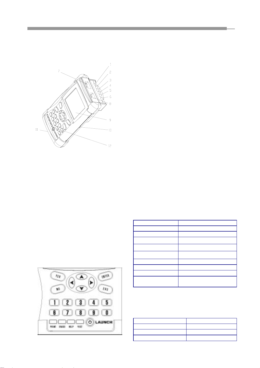
GeneralInformation
KES-200 is a tool specially designed for engine test and
analysis with the following functions: 4channel
oscilloscope, multimeter, ignition waveform test,
starting systemanalysis, charging systemanalysis,
cylinderanalysis,PClink,printandInternetupdate,
etc.
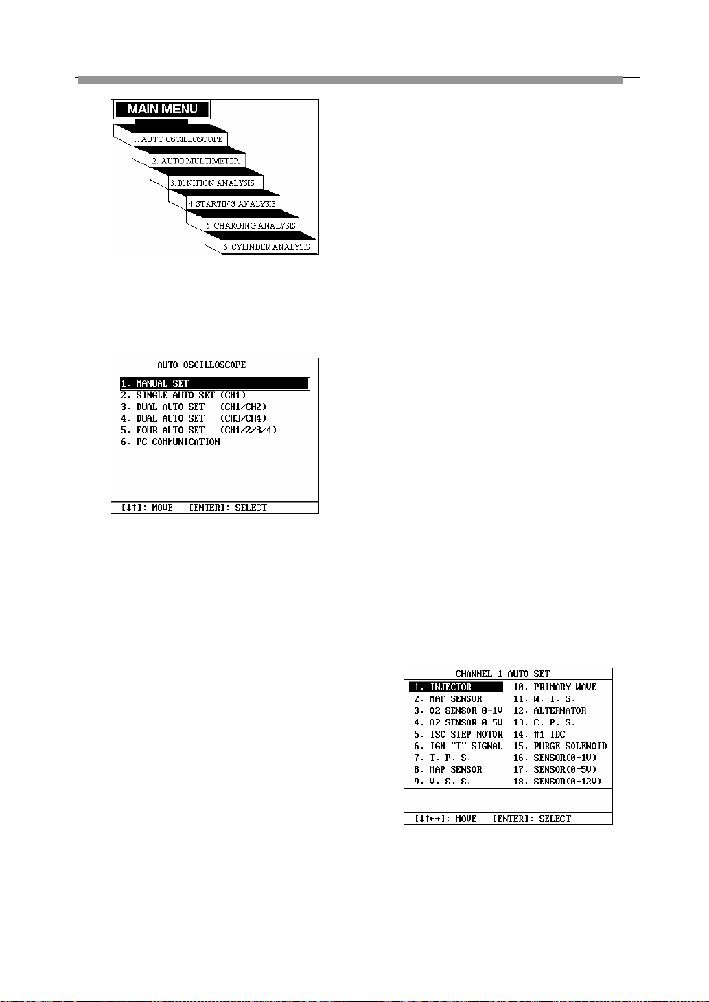
4channel oscilloscope function can be used to test
the output waveform of automobile sensors. KES-200
has a built-in dynamic memory for saving 50
waveforms, including rich information of standard
waveform of vehicle sensors and repairs.
You can make a comparison between a waveform
being tested and a standard waveform and analyze
sensor troubles. In addition, the test method and
troubleshooting help information have been given for x
types of commonly used sensors.
The oscilloscope has a complete display control mode
capable of displaying 4 tested waveforms at the same
time.
Multimeter function is used mainly for measuring
voltage, current, resistance, output frequency, duty
cycle, battery voltage, tachometer, and intake manifold
vacuum.
Ignition waveform test function can be used to test
the primary and secondary waveforms of gasoline
engine and display them in single cylinder waveform,
parade waveform, raster waveform or bar graph. It can
be used to test ignition systems with or without
distributor, and obtain ignition peak voltage, spark
voltage and spark duration (with distributor). The
system gives standard and faulty primary and
secondary waveforms to help the user to analyze
automotive engine troubles.
Starting system analysis function is mainly used to
test the starting voltage and current of engine system.
Starting voltage test is to test the storage voltage of the
battery while starting, it can display the initial and end
voltage value at same time; the current waveform and
its maximal and minimal value can be displayed while
perform starting current test.
Charging system test function is mainly used to test
the AC charging voltage of the alternator. It can also
test the charging current and engine speed.
Cylinder analysis function includes power balance
test, cylinder efficiency test, and relative cylinder
compression pressure test. Power balance test is
applicable to distributor engines with less than 6
cylinders. This function is used to analyze the uniformity
of each cylinder. Both auto and manual test modes are
provided. Cylinder efficiency test is to judge the power
performance of each cylinder by testing the primary
ignition interval of two cylinders adjacent with each
other. Relative cylinder compression pressure test is
applicable to engines with less than 6 cylinders. This
function is used to analyze the uniformity of
compression pressure of each cylinder.
PC link function can transmit the stored waveform
from KES-200 to PC for further analysis, processing,
print. This function can also used to perform software
update.
KES-200 is also equipped with printer interface, which
supports common printers with PCL language. The
printed result may be used to perform further analysis
and reserve.
KES-200 is easy to operate, for it provides help
information to guide the user how to operate.
KES-200 can be updated quickly and easily through
the Internet. The user may download the latest version
of the test software and update their KES-200 from the
LAUNCH website: http://www.cnlaunch.com, to obtain
the latest test technique of LAUNCH.