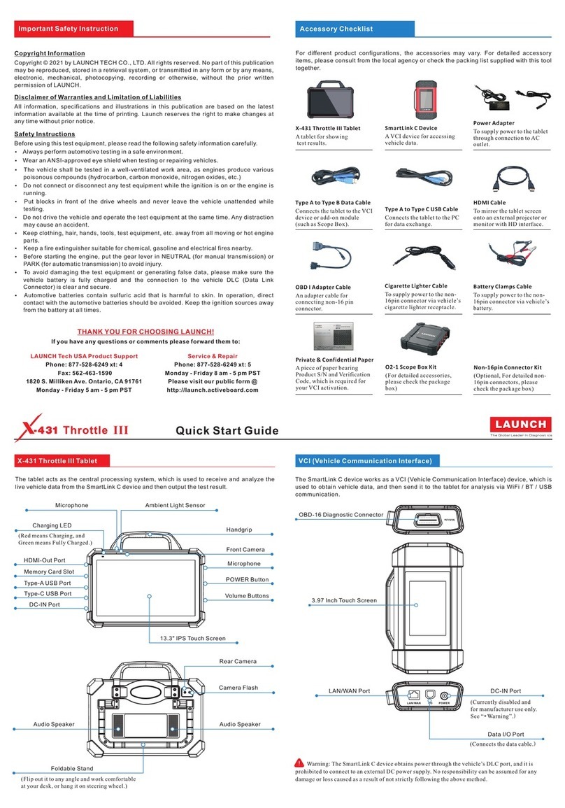
Launch X431 Scopebox User manual

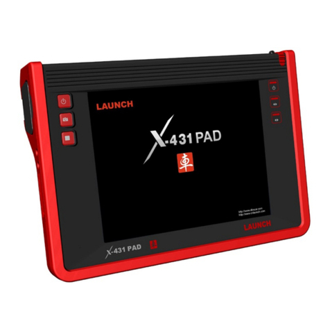
LAUNCH X431 PAD Scopebox User’s Manual
Precaution on Operation
zThe appliance is a sophisticated electronic device, never have it clashed
when in use.
zMain unit screen may flash at the moment of engine ignition, which is
normal.
zYou may unplug the main unit if the program can not be actuated or
confused screen occurs. Plug again to continue the operation.
zMake sure the appliance is properly connected to the DLC to avoid
communication interruptions.
zDuring operation, keep the screen upward and leveled.
zBe careful when plugging and unplugging the main cable and diagnostic
connector. Tighten the screw before operation to avoid unexpected
disconnecting and/or damage to the port.
zHandle with care.Avoid collision. Unplug the power after operation.
zAfter the operation, the stylus shall be inserted into the slot on the main
unit, and put away the cable and connector, etc accessories to the box to
avoid the lost.
zUnplug the power cable by holding the connector, not the cable itself.

LAUNCH X431 PAD Scopebox User’s Manual
Table of Contents
1 FOREWORD......................................................................................1
1.1 INTRODUCTIONS ...........................................................................1
1.2 PRODUCT FEATURES.....................................................................1
1.3 PRODUCT FUNCTION.....................................................................2
1.4 TECHNICAL PARAMETERS..............................................................2
2 STRUCTURE AND ACCESSORIES .................................................3
2.1 SCOPEBOX STRUCTURE................................................................3
2.2 SCOPEBOX ACCESSORIES.............................................................4
3 AUTOMOTIVE OSCILLOSCOPE...................................................... 6
3.1 CONNECTION................................................................................6
3.2 INITIAL INTERFACE INTRODUCTION.................................................6
3.3 OPERATIONS.................................................................................7
3.3.1 Channel selection and attributes setting..............................7
3.3.2 Trigger setting.......................................................................9
3.3.3 Auto calibration...................................................................11
3.3.4 Display settings................................................................. 12
3.3.5 Channel and cursor measurement.................................... 12
3.3.6 File management............................................................... 13
3.3.7 View the software version ................................................. 15
3.3.8 Exit the application............................................................ 15
4 AUTOMOTIVE IGNITION WAVEFORM ..........................................16
4.1 SECONDARY-DISTRIBUTOR IGNITION ANALYSIS.............................16
4.2 SECONDARY-SIMULTANEOUS IGNITION ANALYSIS..........................19
4.3 SECONDARY-DIRECT IGNITION ANALYSIS......................................20
4.4 WAVEFORM ANALYSIS MODE........................................................22

LAUNCH X431 PAD Scopebox User’s Manual
1
1 Foreword
1.1 Introductions
X-431 PAD is a new generation of sophisticated and integrated automotive
diagnostic product with colorful screen and powerful functions developed by
LAUNCH, and Scopebox is an optional function box for X-431 PAD, including
automotive oscilloscope and automotive ignition waveform.
Automotive oscilloscope can make the auto repair technician quickly judged
the faults on automotive electronic equipment and wiring, and the oscilloscope
sweep speed is far greater than the signal frequency of such vehicles, usually
5-10 times of the measured signal. The automotive oscilloscope not only can
quickly capture the circuit signal, but also can slowly display the waveform to
observe and analyze. It can also record and store the tested signal waveform
which can be played back to observe for the fast signal, having great
convenience to failure analysis. Either high-speed signal (e.g.: injection nozzle,
intermittent fault signal) or the slow-speed signal (e.g. the throttle position
change and the oxygen sensor signal) can be observed through automotive
oscilloscope in an appropriate waveform.
The electronic signal can be compared and judged via measuring five
parameters indexes. The five parameters indexes are the amplitude (the
maximum voltage of signal), the frequency (the cycle time of signal), the shape
(the appearance of signal), the pulse width (the duty cycle or the time range of
signal), and the array (the repetition characteristic of signal), which can be
tested, displayed, saved by the automotive oscilloscope. Via the waveform
analysis can further detect the circuit fault on sensors, actuators, circuits, and
electronic control units, etc.
1.2 Product features
zRapidly capture the circuit signal.
zDisplay waveform slowly for observation and analysis.
zRecord and store the tested signal waveform for playback and failure
analysis.
LAUNCH X431 PAD Scopebox User’s Manual
2
zDetect, display and store all the electrical signal of five parameters,
namely amplitude, frequency, shape, pulse width, and array.
1.3 Product function
Provides specialized automotive oscilloscope function and supports ignition
waveform analysis.
1.4 Technical parameters
Scopebox: 4 channels, highest sampling frequency 200MHZ, max storage
depth 64MSa, 8-bit resolution.

LAUNCH X431 PAD Scopebox User’s Manual
2 Structure and Accessories
2.1 Scopebox structure
Fig 2-1 Scopebox Structure Diagram
Table 2-1 shows the ports and indicators for X-431 PAD Scopebox
No. Name Description
1 CH1 Channel 1
2 CH2 Channel 2
3 CH3 Channel 3
4 CH4 Channel 4
5 External trigger External trigger signal
6 Fixed signal
generator Generate a square signal with fixed 1K frequency
3

LAUNCH X431 PAD Scopebox User’s Manual
7 Power indicator Oscilloscope power indicator, which will be steady
red after the oscilloscope is powered on
8 Operating
indicator The indicator will be steady green after the
oscilloscope operated.
9 Communication
indicator After the data communication, the indicator will
blink (Green).
10 Power interface Connect to power supply via the power adapter.
11 B-shaped USB
interface Connect main unit via USB connect line as
separated individual USB devices
2.2 Scopebox accessories
Scopebox includes the secondary pickup cable for 4-channel oscilloscope,
crocodile clips for 4-channel oscilloscope, etc. See Table 2-2.
As the product configuration can be different, the accessories included with the
product may differ from the accessories listed on this manual. Please see the
packing list attached to the product for the detailed accessories.
Table 2-2Accessory checklist
No. Name Picture
1 Secondary ignition pickup for
4-channel oscilloscope
2 Crocodile clips for 4-channel
Oscilloscope
3 Direct ignition extension cord
4

LAUNCH X431 PAD Scopebox User’s Manual
4 6-way universal guide line for
4-channel oscilloscope
5 BNC to 4mm connector test
cable
6 Pin connector for 4-channel
oscilloscope
5

LAUNCH X431 PAD Scopebox User’s Manual
6
3 Automotive Oscilloscope
3.1 Connection
X-431 PAD Scopebox should work with the X431 PAD main unit.
1. Firstly, power on the main unit (Connect one end of the power adaptor into
the power interface of main unit, and the other end to the DC 12V power
supply. Alternatively it can be also powered by cigarette lighter cable and
double clip power cord).
2. Then plug one end of ground cable of oscilloscope into external trigger
channel (GND), the other end should be grounded.
3. Connect one end of probe cable of oscilloscope to the CH1, CH2, CH3, or
CH4 on oscilloscope module, and then connect the other end to related
signal terminal.
Warning: please use the specific capacitance probe when diagnosing the
ignition high voltage line. Never connect the oscilloscope to the ignition
secondary circuit directly.
3.2 Initial interface introduction
Fig. 3-1 displays the initial interface of oscilloscope.

LAUNCH X431 PAD Scopebox User’s Manual
Fig.3-1
Button descriptions:
[Autoset]: It indicates auto trigger setting. Based on the characteristics of
measured signal, the oscilloscope will automatically set the horizontal baseline,
vertical sensitivity and trigger condition so that the waveform can be displayed.
[File]: provideswaveform record and waveform replay.
[View]: Calibration and display settings are available.
[Measure]:includes signal source measurement, cursor measurement and
clear measurement.
[Settings]: displays or hides the parameter settings area including horizontal
settings, vertical settings and trigger settings.
[Start/stop]: starts/stops collecting oscilloscope waveforms.
3.3 Operations
3.3.1 Channel selection and attributes setting
<1> Channel selection
There are two ways available for channel selection: (See Fig. 3-2)
A. Select from the channel column shown at the bottom of the waveform
7

LAUNCH X431 PAD Scopebox User’s Manual
display area;
B. Select from Vertical settings.
Note: For better comparison and identification, each channel and waveform
are marked in different colors.
Fig.3-2
<2> Channel attributes setting
Channel attributes can be set via horizontal settings and vertical settings.
Horizontal Settings
User can make some settings directly by clicking << or >> next to options.
Alternatively, Click located in the upper right corner of the horizontal
settings to make more settings. See Fig. 3-3.
Fig. 3-3
8

LAUNCH X431 PAD Scopebox User’s Manual
Options descriptions:
Time/DIV: click << or >> to adjust;
Y-T Format: click << or >> to adjust. It includes 3 options: Normal, Scan and
Scroll (from right to left).
Vertical Settings
User can make some settings directly by clicking << or >> next to options.
Alternatively, Click located in the upper right corner of the vertical settings
to make more settings. See Fig. 3-4.
Fig. 3-4
Options descriptions:
A. Channel selection;
B. Channel switch selection;
C. Channel voltage adjustment;
D. Channel coupling modes selection: DC, AC or Ground;
E. Channel probe selection;
F. Bandwidth limit switch;
G. Channel reverse phase switch.
3.3.2 Trigger setting
Trigger indicates that when certain waveform meets the conditions that are
predefined according to the requirements, the oscilloscope captures the
waveform and its adjacent section, and then presents it on the screen.
<1> Trigger mode
It is classified into 3 categories: Pulse Width and Edge.
[Edge]: It is the most common and effective trigger mode, which is widely used
9

LAUNCH X431 PAD Scopebox User’s Manual
in most applications. Edge trigger only detects the edges, polarities, and
voltage of signal. When the voltage of measured signal varies as identical as
the preset one (rising edge or falling edge), and the value becomes same as
trigger voltage, the oscilloscope will be triggered and capture the waveform.
[Pulse Width]: Trigger happens when it reaches to the pulse width.
Fig. 3-5 and Fig. 3-6 show edge trigger, pulse width trigger setting interfaces.
Fig. 3-5
Fig. 3-6
<2> Trigger Sweep
Auto, Normal and Single are included.
Auto: It indicates that no matter whether it meets the trigger conditions, it will
refresh the waveform in real time. In this case, the waveform displayed on the
screen seems swaying;
Normal: Only it meets the trigger conditions can trigger be activated.
Otherwise the waveform will keep still.
Single: In this mode, it only captures the waveform that generates for the first
time the trigger conditions are met, and then stops after finishing capture.
10

LAUNCH X431 PAD Scopebox User’s Manual
<3> Trigger source
Trigger source means which channel signal will be measured as trigger object.
Before making settings to trigger mode and voltage of certain channel, you
have to choose the target channel.
3.3.3 Auto calibration
This option enables you to obtain a precise measurement of measured signal.
Auto calibration mainly includes: calibration of analog channel, trigger voltage
calibration of trigger circuit and nonlinear calibration of horizontal baseline
movement.
Click “View” and then click [Calibration], a dialog box similar to Fig. 3-8 will
appear.
Fig. 3-8
Check the box before the channel to select it. To select all, click [Check All]. To
deselect it, just click [Reverse]. After choosing the desired channel(s), click
[Start] to start calibration and [Calibration] button will be temporarily invalid
during calibrating. Click [Stop] to stop calibrating. Once it becomes active, it
indicates calibration has completed.
Notes: In process of calibration, make sure CH1/CH2/CH3/CH4 has no signal
11

LAUNCH X431 PAD Scopebox User’s Manual
input. Moreover, calibration may take several minutes and please be patient to
wait.
3.3.4 Display settings
Click “View” and then [Display settings] to enter the setting screen. See Fig.
3-9.
Fig. 3-9
Click “Vectors” or “Dots” to define display mode. Check/uncheck the box
before Grid to open/close grid display.
3.3.5 Channel and cursor measurement
<1> Channel measurement
Click “Measure” and then [Source], a screen similar to Fig. 3-10 will appear.
Fig. 3-10
<2> Cursor measurement
Click “Measure” and then [Cursor Measure], a screen similar to Fig. 3-11 will
appear.
Note: if no desired channel is selected, the system will take the current source
as the default channel.
12

LAUNCH X431 PAD Scopebox User’s Manual
Fig.3-11 Fig.3-12
Horizontal Measure is for voltage (see Fig. 3-11) and vertical measure is for
timebase (see Fig. 3-12).
Options descriptions:
[A Line / B Line move up / down]: fine adjustment for voltage.Aline is a solid
line and B line is a dotted line;
[A Line / B Line move left / right]: fine adjustment for timebase. A line is a
solid line and B line is a dotted line.
<3> Clear Measurement
Click “Measure” and then [Clear Measure], the system will clear the
measurement result.
3.3.6 File management
<1> Record waveform
This function is used to record waveforms that are collected by oscilloscope at
a period, and save it as data file which can be played back in future.
It can be performed only when the oscilloscope is collecting data in Normal
mode.
Click [File], then select [Record] from the pop-up menu to start recording. See
Fig. 3-13.
13

LAUNCH X431 PAD Scopebox User’s Manual
Fig.3-13
Click [Record] to start recording, and the Record button becomes Stop button.
Click [Stop] to stop recording. While recording, the recorded pages will be
shown on the screen.
<2> Import waveform for playback
The Import function enables you to import the stored waveform file for
playback and review. During replaying, the oscilloscope stops collecting data
automatically.
Click [File], then select [Waveform replay] from the pop-up menu to enter a
screen similar to Fig. 3-14.
Fig.3-14
Select the playback file first, and then click [OK] button to open the waveform
file, then use channel attributes setting to adjust the waveform display.
To delete the waveform file, please enter “My Data” and choose the
14

LAUNCH X431 PAD Scopebox User’s Manual
corresponding folder to perform delete operation.
<3> Print waveform
This option allows you to print out the latest collected data while the
oscilloscope stops collecting data. While printing, the oscilloscope should be in
stop mode.
Click on the shortcut bar to start printing.
3.3.7 View the software version
Click to view the version information of the oscilloscope.
3.3.8 Exit the application
Click to exit the current application.
15

LAUNCH X431 PAD Scopebox User’s Manual
16
4 Automotive Ignition waveform
The ignition system is the system which has greatest impact on the
performances of gasoline engine, as the statistical data shows that nearly half
of the failures are caused by poor work of electrical system. And the
performance tests of engine often start from the ignition system. Nowadays
ignition system includes distributor and distributorless. Distributorless includes
independent ignition and simultaneous ignition.
1. Distributor ignition system i.e. contact breaker with contact-controlled
ignition system (commonly known as the platinum) and contact breaker
with noncontact-controlled ignition system combined with magnet, hall
components or infrared.
2. Independent ignition system: crankshaft sensor send out the ignition
timing signal and cylinder identification signal so that the ignition system
can send out ignition signal to specified cylinder in specified time, each
cylinder has its independent ignition coil.
3. Simultaneous ignition system: two cylinders share one ignition coil, when
two cylinder pistons reach top dead center at the same time (one is
compression, another is the exhaust), two spark plugs will be ignited at
the same time, at this time, the ignition for the former cylinder is in
high-pressure low temperature gas mixture, the ignition is valid, while for
the latter one is in low-pressure high temperature exhaust gas, the
ignition is invalid.
X-431 PAD can test and analyze the secondary signal for various engine
ignition systems.
4.1 Secondary-distributor ignition analysis
Connections: Plug the BNC end of secondary ignition pickup into
CH1/CH2/CH3/CH4 channel of Scopebox, then connect the high-voltage clip
to high-voltage line, and crocodile clips to ground.
Tips: Common ignition sequence (the specific sequence is subject to the
actual engine ignition sequence)

LAUNCH X431 PAD Scopebox User’s Manual
17
Four-stroke in-line four-cylinder: 1—2—4—3, or 1—3—4—2
Four-stroke in-line six-cylinder: 1—5—3—6—2—4, or 1—4—2—6—3—5
Four-stroke in-line eight-cylinder: 1—8—4—3—6—5—7—2
Five-cylinder: 1-2-4-5-3
V 6 engine: generally speaking, based on the person sitting on the driver cab,
if the right side cylinder numbers on the right side, from the front to the back
are as follows: 1, 3, 5; and the cylinder numbers on the left side, from the front
to the back are as follows: 2, 4, 6; then the ignition sequence is: 1-4-5-2-
3-6. If the cylinder numbers on the right side, from the front to the back are as
follows: 2, 4, 6; and cylinder numbers on the left side, from the front to the back
are as follows:1, 3, 5; then the ignition sequence is: 1-6-5-4-3-2.
The Figure 4-1 below shows the normal ignition waveform of distributor ignition
system, the upper one is the secondary waveform, and the lower one is the
primary waveform.
The secondary waveform
Asection is contact open period; B section is make contact period, which is the
magnetizing field of ignition coil.

LAUNCH X431 PAD Scopebox User’s Manual
Fig. 4-1
1) Contact break point: the primary circuit of ignition coil cut off, the
secondary voltage was sensed and increased sharply
2) Ignition voltage: secondary coil voltage overcome the damper of high
voltage line, the contact breaker gap and the spark plug gap to release
magnetizing energy, 1-2 section is the breakdown voltage
3) Spark voltage: For the capacitor discharge voltage
4) Ignition voltage pulse: For the charge and discharge sections
5) Spark line: The inductance discharge process, i.e. the mutual inductance
voltage of ignition coil maintains the conduction of secondary circuit
6) Contact point close the current flow into primary coil, the primary coil
oscillates due to the mutual inductance.
Primary ignition waveform
Section a shows the voltage oscillation on the primary circuit due to the
magnetic induction of spark in the duration;
Section b shows the damped oscillation generated by remaining magnetic field
18
Table of contents
Other Launch Test Equipment manuals

Launch
Launch BST-860 User manual

Launch
Launch Creader CR3001 User manual

Launch
Launch STS600 User manual

Launch
Launch X-431 EURO TAB II User manual

Launch
Launch Creader 5001 User manual

Launch
Launch X-431 ADAS PRO User manual

Launch
Launch X-431 Throttle III User manual

Launch
Launch KES-200 User manual

Launch
Launch BST-460 User manual

Launch
Launch X-431 PROS User manual