LawnMaster LMEBV260 Installation manual

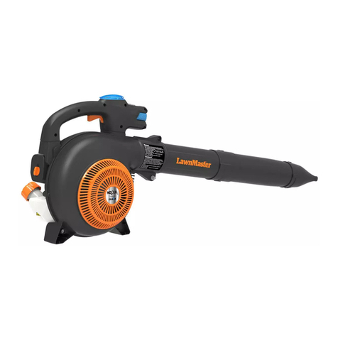
LMEBV260
SAFETY AND OPERATING MANUAL
PETROL
BLOWER VACUUM

2
TECHNICAL DATA 3
INTRODUCTIONS & SAFETY LABELS 4
PARTS LISTING 5
ASSEMBLY 6
CONVERT TO BLOWER 7
FUEL & OIL MIXTURE 8
STARTING PROCEDURE 9
WHEN ENGINE STARTS 10
STARTING A FLOODED ENGINE 10
MAINTENANCE & CARE 10
STORAGE & REPLACEMENT PARTS 11
TROUBLESHOOTING 12
TABLE OF CONTENTS

3
TECHNICAL DATA
Thank you for purchasing the LawnMaster Petrol Blower Vacuum. This manual will
explain the functions and use of the Blower Vacuum. Please read this manual carefully
before operating the unit.
MODEL LMEBV260
MAIN UNIT
ENGINE
Dimensions 340x270x370
Engine Type 1E34FB
Displacement 26 cc / 2-Stroke Engine
Fuel 91 Unleaded Petrol
Fuel & Oil Mixture 40:1
Carburetor Diaphragm with Primer
Ignition CDI
Spark Plug L6RTC
Starter Recoil Starter
Fuel Tank Capacity 500 ml
Weight 4.5 kg
Mulching Tri Blade
Air Speed 216 km/hr
Easy Switch From Blower Vacuum to Blower Only
45L Zipped Catching Bag & Carry Straps
Technical Data is subject to change without notice.

4
INTRODUCTION
The LawnMaster LMEBV260 Blower
Vacuum is designed and purpose built to
be a lightweight and easy to use blower
vacuum, t to tackle any residential chore
while delivering great performance.
With a reliable EBV260 engine, the
LawnMaster Blower Vacuum will deliver
great performance with compromising
quality, comfort, safety, or durability. The
EBV260 is a high performance engine with
leading edge 2-cycle engine
technology that delivers exceptionally high
power at remarkably low displacement
and weight.
IMPORTANT!
The information in this manual refers to
the model and product specications
available at the time of production. While
we ensure all the latest information is
included, there maybe slight changes or
upgraded specications that are different
to the contents of the manual.
Changes to product specications can be
made without prior notice.
CAUTION!
LMEBV260 is equipped with a
spark-arresting muer. Do not operate the
unit without either muer and spark arres-
tor installed and or in functioning order!
ATTENTION STATEMENTS
This manual contains special “attention
statements” that are highlighted with
triangular attention symbols.
WARNING
A statement preceded by WARNING
contains Information that should be acted
upon to prevent serious bodily injury.
CAUTION!
A statement preceded by the word
“CAUTION” contains information that
should be acted upon to prevent machine
damage.
Additional statements that are not
preceded by the attention symbols are:
IMPORTANT!
A statement preceded by the word
“IMPORTANT” is one that possesses
special signicance.
NOTE!
A statement proceeded by word “NOTE”
contains information that is handy to
know and may make your job easier.
Read and follow this manual.
Failure to do so could result in
serious injury.
Wear eye and hearing
protection at all times when
using the unit.

5
Do not operate this machine if you are
tired, ill or under the inuences of alcohol,
drugs, or medicine.
PRODUCT DESCRIPTION
The instructions outlined in this manual is
a helpful resource to help you maximise
the use and preserve the quality and
performance of the engine, whilst also
providing safety information to protect you
and others from harm.
These procedures are general guidelines
are not intended to replace any
regulations and (or) laws that may
otherwise be in place.
If you have any question regarding your
LMEBV260 Blower Vacuum, contact your
local LawnMaster Service Dealership or
contact Steelfort.
Steelfort Head Oce
500 Rangitikei Street,
Palmerston North.
Phone: 06 350 1350
Steelfort Auckland
880 Great South Road,
Penrose, Auckland.
Phone: 09 573 1324
PARTS LISTING
Upper Vacuum Tube / Lower Vacuum Tube
Blower Outlet
Lower Handle Vacuum Inlet Cover
Fuel Tank Upper Handle & On-Off Switch
Starting Cord
Catching Bag
Throttle Control

6
ASSEMBLY
1. Unscrew the knob on the vacuum inlet
cover. The screw should remain on the
cover at all times.
Handy Tip
Use Silicon Lubricating Spray between the
attachments for ease of removal due to
dust build-up.
2. Connect both upper and lower vacuum
tubes together by aligning the two arrows.
Slide-on and twist clockwise to snap into
place.
3. With the arrow on the lower vacuum
tube pointing in the direction of the unit
(facing up), slide the tube into place. Twist
the tube clockwise to lock into place.
4. Open and unzip the catching bag. Put
the ‘elbow tube’ in the bag. Put the small
end of the ‘elbow tube’ through the elastic
hole until it reaches the tapered end.
Zip and close the bag.
5. Unscrew M5x10 from the blower outlet
and place it aside safely. Align the arrows
on the ‘elbow tube’ with the arrow on the
unit on the blower outlet.
Cleaner Cover
6. Push the ‘elbow tube’ in and rotate
anti-clockwise until the locking screw
holes are aligned.
7. Screw M5x10 into place to secure
elbow tube and catching bag.
When you are ready to use the unit, clip
the shoulder straps into the loops that
are attached to the bag. Pull the shoulder
strap over the shoulder and adjust for
comfort. Carry the bag when using the
unit .
Above Image: Step 3 - Sliding nozzle into place
Right: Step 4 - Connecting elbow tube to blower outlet
Vacuum Inlet Cover

7
CONVERT TO BLOWER
Upper Handle & On/ Off Switch
Blower Outlet
Throttle
Cleaner Cover
Fuel Tank
Connect upper blower tube to blower
outlet and reinforce with M5x10.
Connect upper blower tube to the unit
by rotating into place. Connect lower
blower tube to the upper blower tube
with the same rotation motion.
Lower Handle
Starter Cord
CONVERT TO BLOWER
The following instructions is to convert
the Blower Vacuum from vacuum to a
blower unit. Ensure the unit is switched off
and the catching bag is empty.
1. Unscrew the M5x10 on the blower
outlet and place it aside safely.
Un-twist the ‘elbow tube’ clockwise until
the arrows align. Take-off the ‘elblow tube’
and catching bag.
Handy Tip
Use Silicon Lubricating Spray between the
attachments for ease of removal due to
dust build-up.
2. Attach the upper blower tube to the
blower outlet by facing the locking hole
up. Twist clockwise until locking holes
align. Screw in M5x10 to secure the upper
blower tube, then attach the lower blower
tube and nozzle.
3. Place the unit on a at surface, and use
two hands to grip the ribs of the upper
vacuum tube. Twist anti-clockwise then
pull off to remove from the unit.
4. Screw the vacuum inlet cover into place
by hand rmly. The Blower Vacuum has
now been converted.
Vacuum Inlet Cover

8
FUEL & OIL MIXTURE
WARNING
Do not ll the fuel tank to the brim and
also do not add fuel to the tank in a closed
non-ventilated area. Fuel used for this
model is a mixture of unleaded petrol and
approved engine lubricant.
When mixing petrol with two-cycle engine
oil, use only petrol that DOES NOT contain
ETHANOL or METHANOL
(types of alcohols).
Use 91 unleaded petrol to fuel the unit.
This will help avoid possible damage to
the engine fuel lines and other engine
parts.
The engine uses two-stroke fuel. If you
have emission requirements, the mixture
ratio of the fuel to oil should be 40:1.
Appropriate Fuel Mixtures
Be careful, a wrong mixture of the fuel will
cause machine failure.
Petrol
Use 91 Unleaded Petrol.
STORING FUEL
The tank to store the fuel should be clean,
anti-static, high-temperature-resistant, re
prevention and safe.
IMPORTANT
Two-stroke fuel may separate. Shake
fuel container thoroughly before every
use.
Do not mix more fuel than you expect to
use within a month
WARNING
Never transfer or store fuels in the
presence of ammable materials!
Before starting the engine, move the
unit to safe and clear area that is 10-feet
(3-meters) away from any ammable
materials!
WHEN FUELING
Always use extreme care when handling
fuel as fuel is highly ammable!
Never operate this unit if fuel system
components are damaged or are leaking
or while the engine is running!
Never attempt to refuel a hot engine!
Always allow the blower engine to cool
before fueling!
Oil - 1 Part
Petrol - 40 Part
Emissions
Petrol 2-Stroke Oil
1 Litre 25 ml
2 Litre 50 ml
5 Litre 125 ml

9
Never smoke or light any res near the
blower or fuel and only transport and store
fuels in an approved container!
Never place ammable maternal close to
the engine muer!
Never operate the blower without a
functioning muer and or spark arrestor.
Never operate the blower unless it is
properly assembled and in good working
condition!
STARTING THE UNIT
WARNING
Danger from rotating impeller!
The impeller will rotate when the machine
is in operation.
Do not operate the unit unless the intake
cover and machine tubes are properly
installed and in good working order.
Danger from thrown dust and or debris!
Always wear eye protection when
operating the unit!
Do not direct the unit stream towards
people or animals. Never operate this
machine unless all controls are properly
installed and in good working order!
WARNING
The recoil starter can be damaged by the
following:
Do not pull the starter cord to its full
length.
Always engage the starter before cranking
the engine.
Always rewind the starter cord slowly and
never operate the machine if the tubes are
missing or damaged.
STARTING PROCEDURE
1. Turn the switch to on. Prime the fuel
system by repeatedly depressing the fuel
primer bulb until no air bubbles are visible
in the fuel discharge line.
2. Cold Engine Only. Choke the engine
by pulling the choke control to the fully
extended position (choke is closed).
3. Place the machine on the ground, and
hold the machine handle rmly with your
right hand.
4. Pull the starter cord slowly until you feel
the engine.
5. Start the machine by pulling the starter
cord upward in a swift motion rapidly.
If necessary, repeat step 5 two or three
times until the engine starts.
WARM START
If engine is warm, DO NOT USE choke to
start the engine.

10
MAINTENANCE & CARE
WARNING
Before performing any maintenance
on this machine, stop the engine and
disconnect the spark plug wire!
Inspect the engine, tank and hose for
possible fuel leaks, and repair as
necessary and inspect the entire machine
for damage, loose or missing components
or fastenings, and repair as necessary.
EVERY 10 HOURS (MORE FREQUENTLY IN
DUSTY CONDITIONS)
1. Loosen the air cleaner cover retaining
screw, and remove the cover and ler
element.
2. Inspect the element. If the element is
distorted or damaged, replace it with a
new one.
3. Wash the element in clean fuel, and
squeeze or blow dry. Wash the air cleaner
cover in clean fuel, and wipe or blow dry.
4. Install the element and cover, and the
tighten the cover retaining screw.
EVERY 10/15 HOURS
1. Use the spark plug wrench to remove
the spark plug ( turn counter-clockwise to
remove).
2. Clean and adjust the spark plug gap
to 0.6-0.7mm. Replace any damaged or
visibly worn plug with a champion RCJ6Y
or equivalent.
WHEN THE ENGINE STARTS
IMPORTANT
For maximum vacuum performance and
operating life, allow the engine to warm-up
before use.
1. Run the engine at idle speed until
operating temperature is reached (2 to 3
minutes).
2. As the engine warms, open the choke
gradually by slowly pushing the choke
control in to the fully retracted position.
3.The unit should now be ready for use.
If the engine does not start, repeat the
appropriate starting procedures for “hot”
or “cold” engine. If the engine still will
not start, follow the “Starting a Flooded
Engine” procedure (below).
WARNING
Incorrect spark plug installation can result
in serious engine damage!
STARTING A FLOODED ENGINE
1. Disconnect the spark plug lead, and use
the spark plug wrench to remove the plug
in a counterclockwise direction.
2. If the spark plug is fouled or is soaked
with fuel, clean or replace the plug as
required.

11
3. Install the spark plug nger-tight in the
cylinder head, and then tighten it rmly
with the spark plug wrench. If a torque
wrench is available, torque the spark plug
to 148-165 inch pounds.
CAUTION
Never allow dirt or debris to enter the
cylinder bore! Before removing the speak
plug, thoroughly clean the spark plug and
cylinder head area. Allow the engine to
cool before servicing the spark plug.
Incorrect spark plug installation can result
in serious engine damage!
EVERY 50 HOURS
INSPECTION
Inspect the entire machine and tubes
for damage, including loose or missing
components, and repair as necessary.
SPARK PLUG
Replace the spark plug with a champion
L9T(LD), gapped to (0.6-0.7)mm.
FUEL FILTER
Use a wire hook to extract the fuel lter
from inside the fuel lter, and then remove
and wash the ler element in clean fuel.
Before reinstalling the lter, inspect the
condition of the fuel line. If damage or
deterioration is noted, the vacuum should
be removed from service until it can be
inspected by a trained service technician.
STORAGE (30 DAYS OR LONGER)
CLEANING
Thoroughly clean the machine exterior.
INSPECTION
Inspect the entire machine and tubes for
damage, including loose or missing com-
ponents, and repair as necessary.
FUEL
Drain the fuel tank, and the clear the car-
buretor and lines by running the machine
until it stops from lack of fuel.
LUBRICATION
Remove the spark plug, and then pour
approximately 1/4-oz of oil into the cyl-
inder through the spark plug hole. Before
reinstalling the spark plug, pull the recoil
starter 2 to 3 times to distribute the oil
over the cylinder walls.
AIR CLEANER
Remove, clean, and reinstall the lter
element as described under.
ORDERING REPLACEMENT PARTS
Please quote the following data when
ordering replacement parts:
• Type of machine
• Article number of the machine
• Identication number of the machine
• Replacement part number of the part
required
For our latest prices and information
please visit www.steelfort.co.nz

Steelfort
500 Rangitikei Street
Private Bag 11045
Palmerston North, 4442, New Zealand
06 350 1350 | steelfort.co.nz
steelfortnz
SCAN TO VIEW THE
LAWNMASTER RANGE
Steelfort Auckland
880 Great South Road, Penrose
Auckland, 1061, New Zealand
TROUBLESHOOTING
Problem Possible Cause Solution
The Spark Plug
Does Not Spark
Spark Plug
Spark Plug Electrode Is Wet Dry The Electrode
Covered With Carbon Clean Or Replace The Spark Plug
Damaged Insulation Replace Spark Plug
Spark Gap Incorrect Adjust To 0.6-0.7mm
Spark Plug Electrode Burnt Replace Spark Plug
Magneto
Damaged Ht Cable Repair Or Replace
Bad Coil Insulation Replace Coil
Damage To The Wire Coil Replace Coil
The Electronic Firing Unit Is Defective Replace The Defective Unit
The Spark Plug
Is Functioning
Correctly
Compression
Ratio Ok And
Fueling Well
Too Much Fuel In The Cylinder Drain Excess Fuel
Water Or Dirt In The Fuel, Stale Fuel Replace With Fresh Fuel
Fueling Well But
The Compression
Ratio Is Poor
The Cylinder Piston Ring Is Worn Or Damaged Replace Worn Or Damaged Items
The Spark Plug Is Loose Tighten Spark Plug
Carburettor Not
Fueling
No Fuel In The Tank Add Fuel - May Require Priming
Filter Gauze Clogged Clean Filter Gauze Or Replace
Tank Air Hole Clogged Clean Tank Air Hole
The Compression Ratio Is Ok
Filter Clogged Clean Filter
Air Is Able To Pass Through Tighten Fuel Lines To Prevent Air From Penetrating
Air Is Able To Pass Through The Carburettor Connection Tighten Up
Engine Is Overheating Stop The Engine And Let It Cool.
Water In The Fuel Upon Restart, Avoid Long Periods Of Sustained Load.
Carbon Clogged Exhaust Drain And Replace The Fuel
Engine Overheating Fuel Mixture Too Lean Adjust The Carburettor
A Cylinder Covered With Carbon Clean The Cylinder
Engine Knocking Or Making A Noise
Fuel Has Gone Stale Or Bad Replace With Clean, Fresh Fuel
Carbon In The Cylinder Clean The Cylinder
Some Engine Parts Are Worn Or Damaged Replace Worn Engine Parts
Engine Stops Suddenly
The Plug Or Plug Wire Is Loose Firmly Replace If Loose
Piston Seized Change The Piston
Spark Plug Covered In Carbon Clean Or Replace The Spark Plug
e Engine Has Run Out Of Petrol Rell Tank With Fuel
Engine Stops Slowly
Carburettor Clogged Clean e Carburettor
e Air Hole In e Tank Is Clogged Clean e Air Hole
Water In e Fuel Drain And Replace With Fresh Fuel
Table of contents
Other LawnMaster Blower manuals

LawnMaster
LawnMaster NPTBL31AB User manual
LawnMaster
LawnMaster NPTBL26A User manual

LawnMaster
LawnMaster CLBL6015ACE User manual
LawnMaster
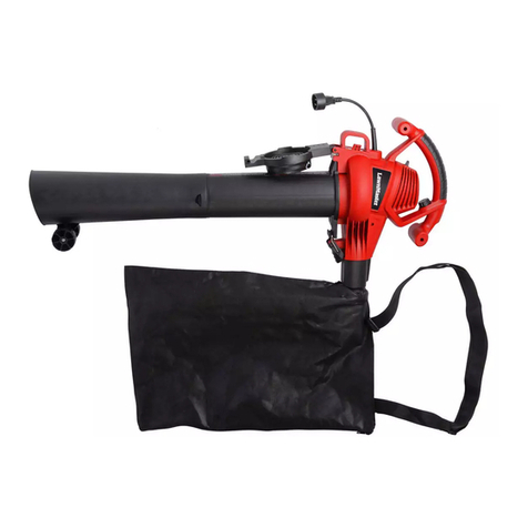
LawnMaster BV1210E 1201 User manual

LawnMaster
LawnMaster NPTBL31AB User manual

LawnMaster
LawnMaster CLBL6015A User manual

LawnMaster
LawnMaster CLBL2406-1 User manual

LawnMaster
LawnMaster BL805E 1201 User manual

LawnMaster
LawnMaster BL705 User manual

LawnMaster
LawnMaster CLBL4016A User manual
