1
1. INTRODUCTION
Thank you for choosing a light stand system. This stand has been specially designed to have a very low loading
height obtained by a multi-mast configuration. The telescopic masts made of treated steel have been generously
sized in order to obtain maximum rigidity, special attention has been placed on security. The ABS (AUTOPIN
BLOCKING SYSTEM) guaranties double security in lifting or operational position, additionally as a third safety
device, each mast can be secured with a locking knob.
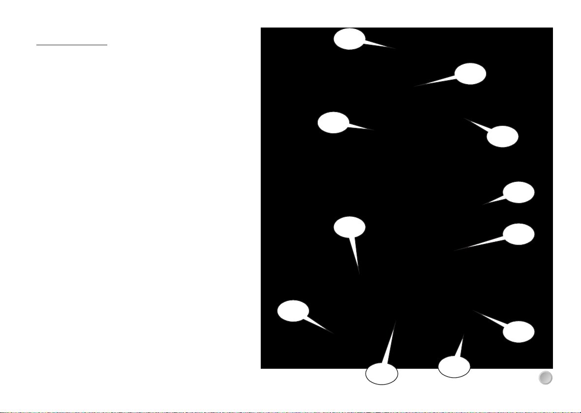
2. TECHNICAL DATA
A: 4 castors for horizontal transport
B: Wide and stable metal base
C: Nylon guided leg sliders
D: Independent adjustable leg braces
E: Auto-levelling galvanised foot plates with attachment holes
F: Solid wide legs for extra stability
G: Large locking knobs (3rd safety device)
H: Protected manual winch with safety friction brake
I : AUTOPIN BLOCKING SYSTEM
J: 4 castors for vertical movement
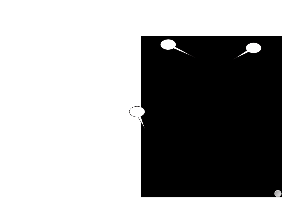
* Lateral play compensation with the masts
* Spirit level
* Friction surfaces on nylon sliders
* All cable pulleys maintenance are free 6
*The fitting of replacement parts not supplied by us or modifications of our design by third parties voids the warranty.
7. SAFETY NOTES!
•Carefully inspect all parts before each use.
•Obey the factory guidelines concerning the load limits as well as the safety codes of material and staff. The choice of
trussing and the stand capacity must be adapted to the load.
•Adequate safety measures must be taken when people work under the loads carried by the truss and the stands. Safety
cables and TUV rated clamps must used on all equipment being supported by the stands.
•The operator must take into account the weight of the holding truss on the stand and deduct it from its allowable load.
•All electrical devices hung on the stand or by the stand must absolutely conform to the technical codes concerning electrical
devices.
•The stand must only be operated in an exactly vertical position.
•All moving parts on the stand should be checked regularly for damaged and wear and tear.
•The steel cable should be checked regularly for fraying.
•Secure the stand to the ground when its used on a sloping surface. Load the stand using only adaptive accessories.
•The load must be centered or evenly distributed on the stand, be careful that the load does not slide to avoid any overhang
of the load.
•Never let the cable only support the entire load. Always use all three load holding systems.
•Never move the stand when it is loaded. Never use the stand to carry people.
•Never lean a ladder on the stand. Never lubricate the winch brake.
•Never exceed the allowed load limits. Never use the stand in outdoor in typhoon weather condition.
•It is dangerous to support a very big size load in windy outdoor condition.
•Do not allow the stand to be used on a soft or moveable surface.
•All sliding and rotating mechanisms used in bad weather must be regularly lubricated.
•Do not lubricate the winch brake. Service must be performed by an authorized repair center.
•The stand must be serviced and inspected a minimum once a year by an authorized service center. Some stands may
require to be serviced more than once a year depending on the usage.
8. DISCLAIMER
* The use of trussing and lifting equipment in temporary or mobile installation is the sole responsibility of the operator.
* During the warranty period, we or one of our contract service organizations will undertake to repair, free of charge any
damage attributable to faulty materials or workmanship for a period of 12 month after date of purchase.
* The warranty does not cover damage due to negligent handling, overload or parts subject to normal wear and tear.
LCG PRODUCTS ST-04 User manual