manuals.online logo
Brands
  1. Home
  2. •
  3. Brands
  4. •
  5. LeapTrend
  6. •
  7. Batteries Charger
  8. •
  9. LeapTrend DCC1212-20 User manual

LeapTrend DCC1212-20 User manual

This manual contains important safety, installation, and operating instructions for the
charger.The following symbols are used throughout the manual to indicate potentially
dangerous conditions or important notes.
08
08
16
16
16
Safety Information
General Information
22
23
23
Product Overview
Installaton
Wiring and Fusing
Operation
Battey Charging Logic
Troubleshooting
Maintenance
Technical Specifications
1 2 3 4 5 6 7
1 2 3
79.0mm
3.11in
213.0mm
188.0mm
7.40in
8.38in
10.35in
79.0mm
263.0mm
3.11in
188.0mm
7.40in
3.11in
79.0mm
313.0mm
12.32in
188.0mm
7.40in
will overall lifespan
applying voltage
Simply low
place
will
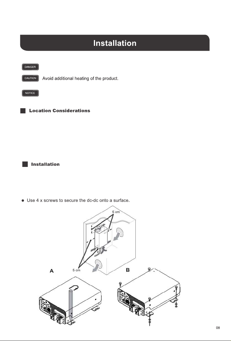
●Have at least 5cm of clearance from all areas and ensure some ventilation for best perfor-
mance.
●Trace the mounting holes with a pencil/pen when placing the DC-DC against the desired
area.
Cannot tip over or fall down.
For installations in small,enclosed spaces, the minimum clearance around the
battery charger must be at least 5cm.
When selecting a location for the DC-DC, make sure that the unit is as close as possible to the
battery you will be charging (auxiliary battery). The charger may be mounted on the cabin of
the vehicle, along a chassis rail, the inner guard of a vehidle, behind the gile or headlight or
even on the side of the radiator. However, you want to make sure that the area is not
susceptible to moisture or other substances as well as potentially high temperatures.
The DC-DC would operate best if there is some air flow.
Only use 12V batteries. Damages due to connecting higher voltage batteries will not
be covered in warranty.
The DC-DC output will connect to the 12V auxiiary or house battery that you are intending to
charge. These batteries may be a diferent chemistry from the starter battery. The DC-DC input
and output terminals are isolated, meaning that the output voltage can be kept stable without
interference from the input circuit. This ensures stable and correct charging of auxiliary
batteries.It is best to place the DC-DC cdloser to the battery you will be charging primarily.
1.Use a screwdriver to loosen the DC output terminals by rotating counterclockwise (CCW).
2.Connect a ring terminal cable from House Battery Positive to the Positive DC Output
Terminal.
3.Use a screwdriver to tighten the DC output terminal by rotating clockwise (CW).
4.Repeat for the House Battery Negative to the Negative DC Output Terminal.
1.Use a screwdriver to loosen the DC input terminals by rotating counterclockwise (CCW).
2.Connect a ring terminal cable from Starter Battery Positive to the Postive DC Input Terminal.
3.Use a screwdriver to tighten the DC Input terminal by rotating clockwise (CW).
The DC-DC will not power on or operate until the D ignition cable is connected. When connect
-ing the DC input, note that the DC-DC will still be off until the lIgnition cable voltage senses.
The DC-DC input will connect to the 12V starter battery that wil be used to charge your auxiliary
or house battery. The starter battery may be a different chemistry from the house battery.The
DC-DC input and output terminals are isolated, meaning that the output voltage can be kept
stable without interference from the input circuit. This ensures stable and correct charging of
auxiliary batteries.
4.Repeat for the Starter Battery Negative to the Negative DC Input Terminal.
The D + terminal will be located on the output side but connects to the DC ignition circuit of
the input starter battery. This may be in the engine bay fuse block for somevehides. Refer to
your own vehicles electrical diagram for D wiring placementmay require splicing or cable
adjustments to connect correctly to your ignition circuit.
mode
Assuming correct D+ ignition cable wiring, then the mode indicator will be on.
selection switch.
The battery types that can be set to charge are standard lead-acid battery (STD battery), colloid
sealed lead battery (GEL battery), AGM battery, lthium iron phosphate (LFP battery).
●The mode selection switch (as shown in the figurebelow) can be configured to charge STD,
GEL,AGM and LFP batteries (just point the white part of the switch to the corresponding
indicator).
●STD, GEL, and AGM have adsorbed charge and floating batteries.
●LFP has an adsorbed charge, but no f1oating charge.
●
Mode Selection Switch
The POWER mode can be used as a power supply.
16
17
After the absorption stage, the voltage of the battery wil reduce to the float voltage setpoint and
current will also reduce to a low maintenance mode to prevent the battery from discharging and
offsetting any self-discharge. Heavier battery discharge may set controller back to Bulk/Absorp-
tion to replenish energy lost while energy is available.
The DC-DC have reactivation feature to awaken a sleeping lithium battery. The protection circuit of
Lithium batteries will typicaly turn the battery off and make it unusable if overdischarged.
This can happen when storing a Lithium pack in a discharged state for any length of time as self.
discharge would gradualy deplete the remaining charge. Without the wake-up feature to reactivate
and recharge batteries, these batteries would become unserviceable and the packs would be
discarded. A small charge current wil be applied to the house battery to activate the protection
circuit and if a correct cell voltage can be reached, it starts a normal charge.
19

This manual suits for next models

4

Popular Batteries Charger manuals by other brands

GNB Tubular LMX Installation and operating instructions

GNB

GNB Tubular LMX Installation and operating instructions

HEINE Charger 30 manual

HEINE

HEINE Charger 30 manual

Hitachi UC 14YF2 instruction manual

Hitachi

Hitachi UC 14YF2 instruction manual

P.I.T. PH20-3.0A user manual

P.I.T.

P.I.T. PH20-3.0A user manual

Century CC6121.2 owner's manual

Century

Century CC6121.2 owner's manual

A. & H. Meyer ZENS PuK 2 quick start guide

A. & H. Meyer

A. & H. Meyer ZENS PuK 2 quick start guide

Purkeys BOSS-01 Guide

Purkeys

Purkeys BOSS-01 Guide

VersaLogic VersaCharger Manual instructions

VersaLogic

VersaLogic VersaCharger Manual instructions

StarTech.com ST7C51224 quick start guide

StarTech.com

StarTech.com ST7C51224 quick start guide

APPLIED ACOUSTICS CSPP Operation manual

APPLIED ACOUSTICS

APPLIED ACOUSTICS CSPP Operation manual

VOLTCRAFT SPS-1200/R operating instructions

VOLTCRAFT

VOLTCRAFT SPS-1200/R operating instructions

Thunderbolt 60449 owner's manual

Thunderbolt

Thunderbolt 60449 owner's manual

Parkside PDSLG 20 A1 Translation of the original instructions

Parkside

Parkside PDSLG 20 A1 Translation of the original instructions

WEMPE WeTech WTC680 user manual

WEMPE

WEMPE WeTech WTC680 user manual

EINHELL 10.022.21 operating instructions

EINHELL

EINHELL 10.022.21 operating instructions

Cocoon HE190045A Getting started guide

Cocoon

Cocoon HE190045A Getting started guide

Sony CUH-ZDC1 instruction manual

Sony

Sony CUH-ZDC1 instruction manual

1TAC Safety charge user manual

1TAC

1TAC Safety charge user manual

manuals.online logo
manuals.online logoBrands
  • About & Mission
  • Contact us
  • Privacy Policy
  • Terms and Conditions

Copyright 2025 Manuals.Online. All Rights Reserved.