manuals.online logo
Brands
  1. Home
  2. •
  3. Brands
  4. •
  5. LED Group
  6. •
  7. Lighting Equipment
  8. •
  9. LED Group ROBUS RKN12050DP-01 User manual

LED Group ROBUS RKN12050DP-01 User manual

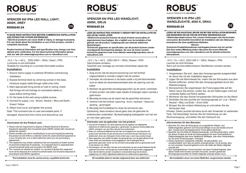
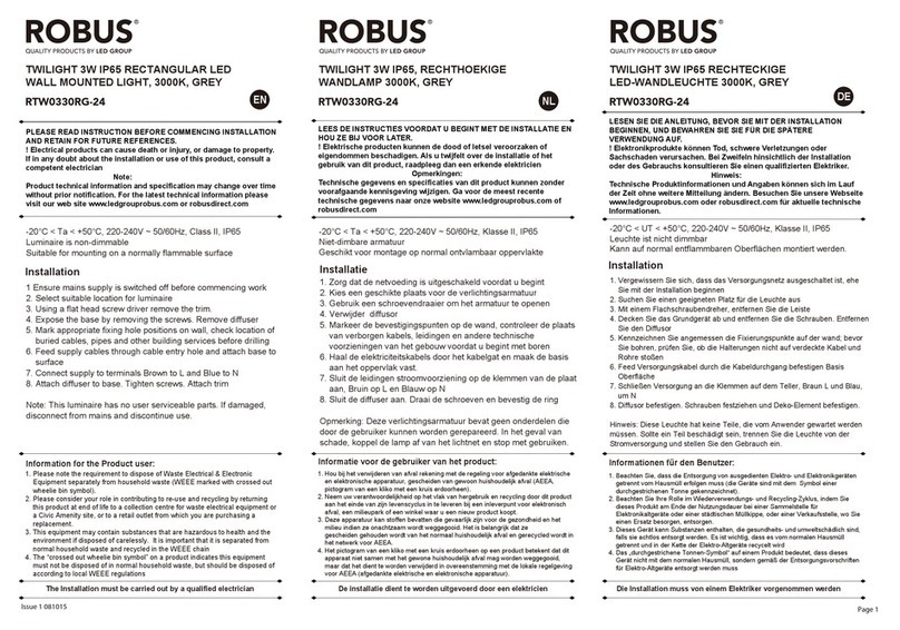
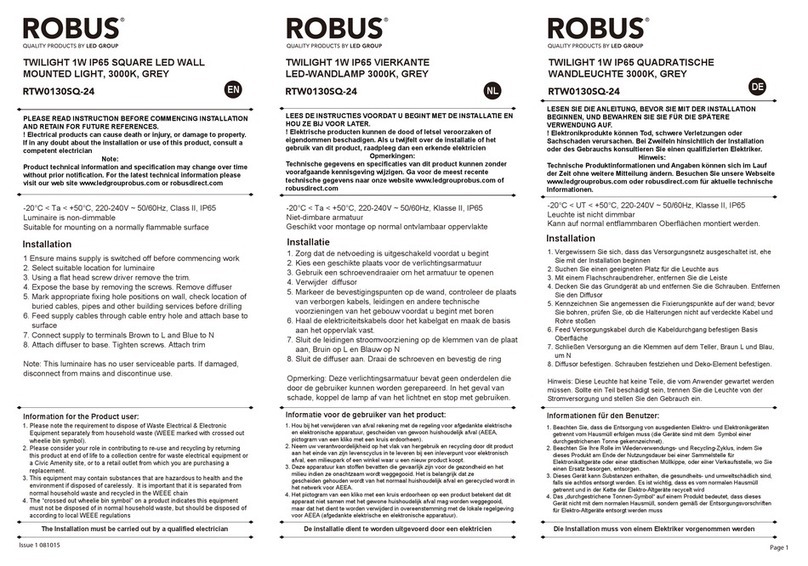
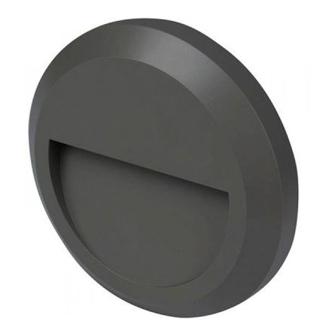
RKN12050DP-01
KINGSTON 120W LED LOW BAY IP20,
WHITE, 5000K, 1.2M, 3 STEP DIMMABLE
RKN12050DP-01
KINGSTON 120W LED LOW BAY, IP20,
WIT, 5000K, 1.2M, 3-STAPS DIMMEN
1. Ensure mains supply is switched off before commencing work.
2. Select suitable location for mounting luminaire.
3. Lens options are 60o, 90oor opal. Remove end cap and the
lens, and then replace Different lens option.
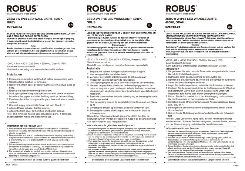
4. Attach the wall mounted brackets to the back of fitting as per
figure 3. If suspended mounting, choose the brackets as
per figure 6.
5. Mark appropriate fixing hole positions on the ceiling or wall,
check location of buried cables, pipes and other building
services before drilling.
6. Connect the power supply to the terminal of fitting as per
figure3.
7. Attach the fitting onto wall and ensure it is secure
Note: no matter it is wall mounting or suspended mounting,
please ensure the mounted screws are tighten and secure.
INSTRUCTION MANUAL
PLEASE READ INSTRUCTION BEFORE COMMENCING INSTALLATION AND RETAIN FOR FUTURE REFERENCES.
! Electrical products can cause death or injury, or damage to property. If in any doubt about the installation or use of this product,
consult a competent electrician
Note:
Product technical information and specification may change over time without prior notification. For the latest technical
information please visit our web site www.ledgrouprobus.com or robusdirect.com
Issue 1 200818 Page 1
Information for the Product user:
Installation
1. Please note the requirement to dispose of Waste Electrical & Electronic Equipment separately from household waste
(WEEE marked with crossed out wheelie bin symbol).
2. Please consider your role in contributing to re-use and recycling by returning this product at end of life to a collection centre
for waste electrical equipment or a Civic Amenity site, or to a retail outlet from which you are purchasing a replacement.
3. This equipment may contain substances that are hazardous to health and the environment if disposed of carelessly. It is
important that it is separated from normal household waste and recycled in the WEEE chain
4. The “crossed out wheelie bin symbol” on a product indicates this equipment must not be disposed of in normal household
waste, but should be disposed of according to local WEEE regulations
The Installation must be carried out by a qualified electrician
-20°C < Ta < +40°C, 220V – 240V ~ 50/60Hz, Class I, IP20
Suitable for mounting on a normally flammable surface.
Height of mounting: 2.5m-3.5m, Detection range: Max. radius 6m.
-20°C < Ta < +40°C, 220V – 240V ~ 50/60Hz, Klasse I, IP20
Geschikt voor montage op normal ontvlambare oppervlakte
Hoogte van de montage: 2.5m-3.5m, Detectiebereik: Max. straal
6m.
Installatie
LEES DE INSTRUCTIES VOORDAT U BEGINT MET DE INSTALLATIE EN HOU ZE BIJ VOOR LATER.
! Elektrische producten kunnen de dood of letsel veroorzaken of eigendommen beschadigen. Als u twijfelt over de installatie of
het gebruik van dit product, raadpleeg dan een erkende elektricien
Opmerkingen:
Technische gegevens en specificaties van dit product kunnen zonder voorafgaande kennisgeving wijzigen. Ga voor de meest
recente technische gegevens naar onze website www.ledgrouprobus.com of robusdirect.com
Informatie voor de gebruiker van het product:
1. Hou bij het verwijderen van afval rekening met de regeling voor afgedankte elektrische en elektronische apparatuur, gescheiden van
gewoon huishoudelijk afval (AEEA, pictogram van een kliko met een kruis erdoorheen).
2. Neem uw verantwoordelijkheid op het vlak van hergebruik en recycling door dit product aan het einde van zijn levenscyclus in te
leveren bij een inleverpunt voor elektronisch afval, een milieupark of een winkel waar u een nieuw product koopt.
3. Deze apparatuur kan stoffen bevatten die gevaarlijk zijn voor de gezondheid en het milieu indien ze onachtzaam wordt weggegooid.
Het is belangrijk dat ze gescheiden gehouden wordt van het normaal huishoudelijk afval en gerecycled wordt in het netwerk voor
AEEA.
4. Het pictogram van een kliko met een kruis erdoorheen op een product betekent dat dit apparaat niet samen met het gewone
huishoudelijk afval mag worden weggegooid, maar dat het dient te worden verwijderd in overeenstemming met de lokale regelgeving
voor AEEA (afgedankte elektrische en elektronische apparatuur).
De installatie dient te worden uitgevoerd door een elektricien
EN NL
1.With sufficient natural light.
the fitting will not switch on
when movement is detected
(Default: Lux control is disabled)
2.When sensor detects
movement and there is
insufficient natural light, the
fitting will switch on (100%
brightness)
3. After activation and no
movement detected the fitting
goes into Hold Time Period
(Default 1 Mins,).
When Hold Time has Elapsed
the fitting enters Standby
Time Period (Default 10%
Output, 30Mins)
4. The fitting will switch off after
Standby Period has elapsed
(Default 30Mins)
3.Als er na activering geen
beweging meer wordt
gedetecteerd, schakelt de
armatuur over op de
Wachttijd-periode (standaard
1 min).Wanneer de Wachttijd
voorbij is, gaat de armatuur over
op de Waaktijd (standaard 10%
lichtafgifte, 30Mins)
4.De armatuur gaat uit
wanneer de Wachttijd
voorbij is (Standaard
30Mins)
Setting sensor table
Daylight sensor
Hold time
Detection Area
I
II
III
IV
1 2
100%
75%
50%
10%
1 2
Disable
50Lux
10Lux
2Lux
I
II
III
IV
Stand-by dimming
1 2
10%
20%
30%
50%
I
II
III
IV
1 2 3
5S
30S
1min
5min
10min
20min
30min
I
II
III
IV
V
VI
VII
Stand-by time
1 2 3
0S
10S
1min
5min
10min
30min
1H
+∞
I
II
III
IV
V
VI
VII
VIII
Microwave sensor
1.Bij voldoende natuurlijk licht,
gaat de armatuur niet aan
wanneer beweging wordt
gedetecteerd (Standaard:
Lux-bediening uitgeschakeld)
2.Wanneer de sensor beweging
detecteerd en er is onvoldoende
natuurlijk licht, gaat de armatuur
aan (100% helderheid)
Microgolfsensor
Tabel instellingen sensor
Daglichtsensor
Wachttijd
Detectiegebied
I
II
III
IV
1 2
100%
75%
50%
10%
1 2
Uitschakelen
50Lux
10Lux
2Lux
I
II
III
IV
Dimniveau
waakstand
1 2
10%
20%
30%
50%
I
II
III
IV
1 2 3
5S
30S
1min
5min
10min
20min
30min
I
II
III
IV
V
VI
VII
Waakstandtijd
1 2 3
0S
10S
1min
5min
10min
30min
1H
+∞
I
II
III
IV
V
VI
VII
VIII
1. Zorgdat het lichtnet is uitgeschakeldvoordat u begint.
2. Kieseengeschikteinstallatieplaatsvoor de armatuur.
3. De lensoptieszijn 60o, 90oof opaal. Verwijder de eindkapen de
lens enzet dan terug op hunplaats. Verschillendelensopties.
4. Bevestig de wandmontagebeugelsaan de achterkant van de
armatuurzoals op afbeelding 3.
Kiesbijophangmontagevoorbeugelszoalsaangegeven op
afbeelding 6.
5. Markeergepastebevestigingspunten op het plafond of de
muurenganadat u geen verborgenkabels,
leidingenenanderevoorzieningen van het
gebouwkuntbeschadigenvoordat u begintteboren.
6. Sluit de stroombronaan op de aansluitklem van de
armatuurzoalsaangegeven op afbeelding 3.
7. Bevestig de armatuurtegen de muurenzorgdatdezegoed vast zit
RKN12050DP-01 RKN12050DP-01
KINGSTON 120W LED LOW BAY DECKENLEUCHTE, IP20,
WEIß, 5000K, 1.2M, 3-STUFEN-DMMER
Installation
-20°C < UT < +40°C, 220-240V ~ 50/60Hz, Klasse I, IP20
Kann auf normal entflammbaren Oberflächen montiert werden.
Montagehöhe: 2,5 m-3,5 m, Erfassungsbereich: max. Radius 6m.
Installation
-20°C < Ta < +40°C, 220-240V ~ 50/60Hz, Classe I, IP20
Convient à une installation sur une surface normalement inflammable
Hauteur de montage: 2,5 m - 3,5 m, plage de détection: max. rayon 6m.
LESEN SIE DIE ANLEITUNG, BEVOR SIE MIT DER INSTALLATION BEGINNEN, UND BEWAHREN SIE SIE FÜR DIE SPÄTERE
VERWENDUNG AUF.
! Elektronikprodukte können Tod, schwere Verletzungen oder. Sachschaden verursachen. Bei Zweifeln hinsichtlich der Installation
oder des Gebrauchs konsultieren Sie einen qualifizierten Elektriker.
Hinweis:
Technische Produktinformationen und Angaben können sich im Lauf der Zeit ohne weitere Mitteilung ändern. Besuchen Sie
unsere Webseite www.ledgrouprobus.com oder robusdirect.com für aktuelle technische Informationen.
Page 2
Informationen für den Benutzer:
1. Beachten Sie, dass die Entsorgung von ausgedienten Elektro- und Elektronikgeräten getrennt vom Hausmüll erfolgen muss (die
Geräte sind mit dem Symbol einer durchgestrichenen Tonne gekennzeichnet).
2. Beachten Sie Ihre Rolle im Wiederverwendungs- und Recycling-Zyklus, indem Sie dieses Produkt am Ende der Nutzungsdauer bei
einer Sammelstelle für. Elektronikaltgeräte oder einer städtischen Müllkippe, oder einer Verkaufsstelle, wo Sie einen Ersatz besorgen,
entsorgen.
3. Dieses Gerät kann Substanzen enthalten, die gesundheits- und umweltschädlich sind, falls sie achtlos entsorgt werden. Es ist wichtig,
dass es vom normalen Hausmüll getrennt und in der Kette der Elektro-Altgeräte recycelt wird
4. Das „durchgestrichene Tonnen-Symbol“ auf einem Produkt bedeutet, dass dieses. Gerät nicht mit dem normalen Hausmüll, sondern
gemäß der Entsorgungsvorschriften für Elektro-Altgeräte entsorgt werden muss
Die Installation muss von einem Elektriker vorgenommen werden
VEUILLEZ LIRE LES INSTRUCTIONS AVANT DE COMMENCER L’INSTALLATION ET CONSERVEZ-LES POUR TOUTES UTILISATIONS
FUTURES.
Les produits électriques peuvent causer la mort, de graves blessures ou des dégâts matériels. Si vous avez des doutes sur l’installation
ou sur l’utilisation de ce produit, veuillez consulter un électricien compétent.
Remarque :
Les informations techniques et caractéristiques peuvent changer au fil du temps sans notification préalable. Pour rester informé de ces
possibles modifications, veuillez consulter le site internet www.ledgrouprobus.com ou robusdirect.com.
Informations pour l’utilisateur du produit :
1. Veuillez, s’il vous plait, noter l’importance de disposer des Déchets d’Equipement Electriques et Electroniques séparément des
déchets ménagers (DEEE représenté par une poubelle barrée d’une croix).
2. Veuillez tenir compte de l’importance de votre contribution à la réutilisation et au recyclage de ce produit en fin de vie en le retournant
dans un centre de collecte de déchets des équipements électriques ou dans le point de vente à partir duquel vous effectuez l’achat du
produit de remplacement.
3. Cet équipement peut contenir des substances dangereuses pour la santé et l’environnement s’il est jeté n’importe où. Il est important
de le séparer des ordures ménagères et le recycler dans une consigne DEEE appropriée.
4. La “poubelle barrée d’une croix” présent sur le produit indique que cet appareil ne doit pas être jeté dans les ordures ménagères mais
doit être éliminé conformément à la réglementation DEEE locale.
L’installation doit être effectuée par un électricien qualié
DE FR
1. Bei ausreichend Tageslicht
schaltet sich die Leuchte nicht
ein, wenn eine Bewegung
erfasst wird. (Standardmäßige
Einstellung: Lux-Steuerung
deaktiviert)
2. Wenn der Sensor eine
Bewegung wahrnimmt und es
ist nicht genügend Tageslicht
vorhanden, schaltet sich die
Leuchte ein (100% Helligkeit).
Mikrowellensensor
1. Quand la lumière naturelle
suffit, le luminaire ne s’allume
pas à la détection de présence
(réglage par défaut :
commande par lux désactivée)
2. Le luminaire s’allume
(luminosité 100 %) quand le
capteur détecte un déplacement
alors que la lumière naturelle
est trop faible.
Capteur à micro-ondes
3. Wenn nach der Aktivierung
keine Bewegung erfasst wird,
schaltet die Leuchte in Haltezeit
(standardmäßige Einstellung
1 Min.). Wenn die Haltezeit
abgelaufen ist, schaltet die
Leuchte in Stand-by
(standardmäßige Einstellung
10% Leistungsabgabe, 30Mins).
4. Nach Ablauf der Stand-by-Zeit
schaltet sich das Licht aus
(standardmäßige Einstellung
30Mins).
3.Le luminaire reste allumé
pendant la durée de rémanence
programmée (réglage par
défaut : 1 minutes) en l’absence
de toute détection de nouveaux
déplacements.À la fin de ce délai,
le luminaire passe en mode veille
programmée (réglage par défaut :
luminosité 10 %, durée 30 minutes)
4.Le luminaire s’éteint à la fin
de la durée de veille
programmée (réglage par
défaut : durée 30 minutes)
Einstellungstabelle Sensor
Tageslichtsensor
Haltezeit
Erfassungsbereich
I
II
III
IV
1 2
100%
75%
50%
10%
1 2
deaktivieren
50Lux
10Lux
2Lux
I
II
III
IV
Stand-by Dimmer
1 2
10%
20%
30%
50%
I
II
III
IV
1 2 3
5S
30S
1min
5min
10min
20min
30min
I
II
III
IV
V
VI
VII
Stand-by-Zeit
1 2 3
0S
10S
1min
5min
10min
30min
1H
+∞
I
II
III
IV
V
VI
VII
VIII
Tableau de réglage de
détecteur de présence
Capteur crépusculaire
Durée de rémanence
Zone de détection
I
II
III
IV
1 2
100%
75%
50%
10%
1 2
désactiver
50Lux
10Lux
2Lux
I
II
III
IV
Veille en luminosité
réduite
1 2
10%
20%
30%
50%
I
II
III
IV
1 2 3
5S
30S
1min
5min
10min
20min
30min
I
II
III
IV
V
VI
VII
Veille programmée
1 2 3
0S
10S
1min
5min
10min
30min
1H
+∞
I
II
III
IV
V
VI
VII
VIII
1. Vergewissern Sie sich, dass die Stromzufuhr ausgeschaltet ist,
bevor Sie mit der Installation beginnen.
2. Wählen Sie einen geeigneten Platz für die Montage der Leuchte
aus.
3. Die Linsen sind in den Optionen 60o, 90ooder matt erhältlich.
Abschlussdeckel und Linse abnehmen und dann die Linse
austauschen.
4. Befestigen Sie die Wandmontageklammern wie in Abbildung 3
gezeigt an der Rückseite der Leuchte.Bei Hängemontage
Klammern wie in Abbildung 6 gezeigt wählen.
5. Zeichnen Sie die passenden Löcher für die Installation an der
Decke oder der Wand an;überprüfen Sie vor dem Bohren, dass
keine unter Putz liegenden Kabel, Rohre oder andere Leitungen
beschädigt werden.
6. Schließen Sie den Strom wie in Abbildung 3 gezeigt an die
Anschlussklemme der Leuchte an.
7. Befestigen Sie die Leuchte an der Wand und achten Sie darauf,
dass alles festsitzt.
KINGSTON 120W FAIBLE HAUTEUR, IP20, BLANC,
5000K, 1,2M, 3 NIVEAUXD’INTENSITÉ
1. Vérifier que l’alimentationélectriqueestcoupéeavant de commencer
l’installation.
2. Sélectionner un emplacement approprié pour le luminaire.
3. Les options de diffuseur 60°, 90° et opalesontdisponibles. Enlever
le capot d’extrémité et remplacer le diffuseur. Différentsdiffuseursen
option.
4. Fixer les étriers de support mural à l’arrière du luminaire
commeillustréen figure 3. Encas de pose en suspension,
sélectionner les supports commeillustréen figure 6.
5. Repérer les trous de fixation appropriéscontre le murou au plafond,
contrôlerl’emplacement des câbles souterrains, canalisations
ouautres servitudes avant de percer.
6. Connecter l’alimentationélectrique au bornier du support
commeillustréen figure 3.
7. Fixer le support au mur et vérifiersa bonne tenue
Page 3
1 2
3 4
5 6
1203mm
208mm
RKNOPL
RKNL60
RKNL90
47mm
LN
Information for the Product user:
1. Please note the requirement to dispose of Waste Electrical & Electronic Equipment separately from household waste
(WEEE marked with crossed out wheelie bin symbol).
2. Please consider your role in contributing to re-use and recycling by returning this product at end of life to a collection centre
for waste electrical equipment or a Civic Amenity site, or to a retail outlet from which you are purchasing a replacement.
3. This equipment may contain substances that are hazardous to health and the environment if disposed of carelessly. It is
important that it is separated from normal household waste and recycled in the WEEE chain
4. The “crossed out wheelie bin symbol” on a product indicates this equipment must not be disposed of in normal household
waste, but should be disposed of according to local WEEE regulations
The Installation must be carried out by a qualified electrician

Other LED Group Lighting Equipment manuals

LED Group ROBUS SPENCER RSN0640-24 User manual

LED Group

LED Group ROBUS SPENCER RSN0640-24 User manual

LED Group ROBUS RVE01440DME-01 User manual

LED Group

LED Group ROBUS RVE01440DME-01 User manual

LED Group ROBUS RZE940-24 User manual

LED Group

LED Group ROBUS RZE940-24 User manual

LED Group Robus R8MTS User manual

LED Group

LED Group Robus R8MTS User manual

LED Group Robus RTK1240-01 User manual

LED Group

LED Group Robus RTK1240-01 User manual

LED Group ROBUS VEGAS RVA12RGBW6710-30 User manual

LED Group

LED Group ROBUS VEGAS RVA12RGBW6710-30 User manual

LED Group ROBUS R2WLEDNMEAU-01 User manual

LED Group

LED Group ROBUS R2WLEDNMEAU-01 User manual

LED Group ROBUS R8EMLED User manual

LED Group

LED Group ROBUS R8EMLED User manual

LED Group ROBUS ROBIN RFS10165GZ-01 User manual

LED Group

LED Group ROBUS ROBIN RFS10165GZ-01 User manual

LED Group ROBUS R18230DL-01 User manual

LED Group

LED Group ROBUS R18230DL-01 User manual

LED Group Robus RVB007RGB10I65 User manual

LED Group

LED Group Robus RVB007RGB10I65 User manual

LED Group ROBUS RAML7P53038-25 User manual

LED Group

LED Group ROBUS RAML7P53038-25 User manual

LED Group Robus R112LEDCP-01 User manual

LED Group

LED Group Robus R112LEDCP-01 User manual

LED Group ROBUS TWILIGHT RTW0230C-24 User manual

LED Group

LED Group ROBUS TWILIGHT RTW0230C-24 User manual

LED Group ROBUS R8MU User manual

LED Group

LED Group ROBUS R8MU User manual

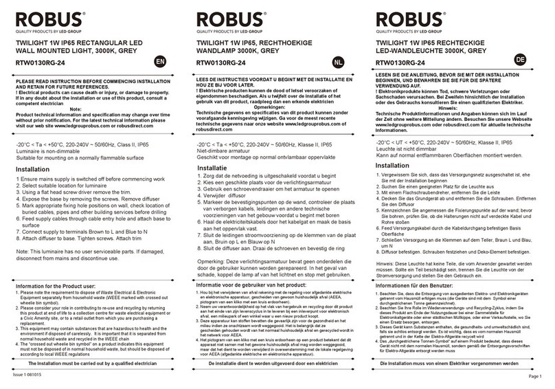
LED Group ROBUS RTW0130RG-24 User manual

LED Group

LED Group ROBUS RTW0130RG-24 User manual

LED Group ROBUS SPACEMAN R405MK-WW User manual

LED Group

LED Group ROBUS SPACEMAN R405MK-WW User manual

LED Group Robus RLU18X0S-01 User manual

LED Group

LED Group Robus RLU18X0S-01 User manual

LED Group ROBUS R3011LED240CW-13 User manual

LED Group

LED Group ROBUS R3011LED240CW-13 User manual

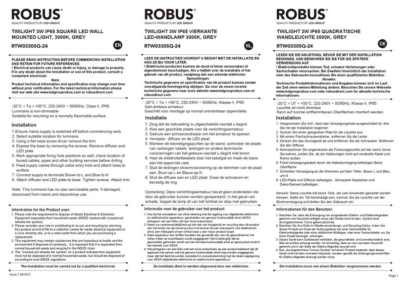
LED Group ROBUS TWILIGHT RTW0330SQ-24 User manual

LED Group

LED Group ROBUS TWILIGHT RTW0330SQ-24 User manual

LED Group ROBUS RTW0330C-24 User manual

LED Group

LED Group ROBUS RTW0330C-24 User manual

LED Group ROBUS TWILIGHT RTW0330RG-24 User manual

LED Group

LED Group ROBUS TWILIGHT RTW0330RG-24 User manual

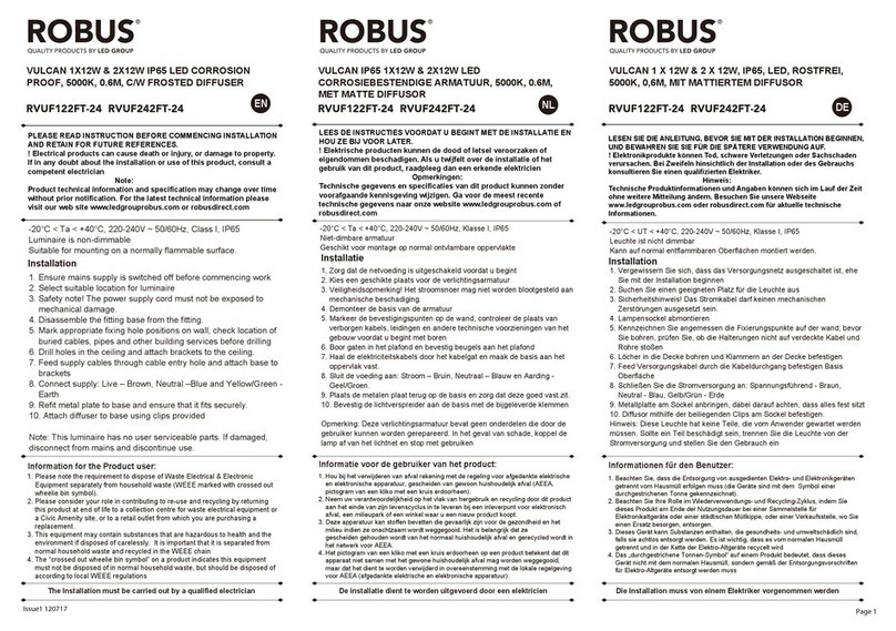
LED Group Robus RVUF122FT-24 User manual

LED Group

LED Group Robus RVUF122FT-24 User manual

LED Group Robus R8EM User manual

LED Group

LED Group Robus R8EM User manual

Popular Lighting Equipment manuals by other brands

Excelitas Technologies X-Cite 120LEDBoost quick start guide

Excelitas Technologies

Excelitas Technologies X-Cite 120LEDBoost quick start guide

OmniSistem OmniSpot 250 user manual

OmniSistem

OmniSistem OmniSpot 250 user manual

ELEGANT Elitco Lighting C202 installation instructions

ELEGANT

ELEGANT Elitco Lighting C202 installation instructions

Satco Products S3680 Catalogue

Satco Products

Satco Products S3680 Catalogue

Unex Float LED operating manual

Unex

Unex Float LED operating manual

Luminaire led ARV17/YRV17 LED installation guide

Luminaire led

Luminaire led ARV17/YRV17 LED installation guide

Code 3 M180L Series Installation and operating instructions

Code 3

Code 3 M180L Series Installation and operating instructions

Verbatim 52948 instruction manual

Verbatim

Verbatim 52948 instruction manual

American DJ FREQ 16 Strobe User instructions

American DJ

American DJ FREQ 16 Strobe User instructions

Pyroistech FJORD-X2-1330-1550 quick start guide

Pyroistech

Pyroistech FJORD-X2-1330-1550 quick start guide

Displays2go SEG LIGHTBOX Assembly instructions

Displays2go

Displays2go SEG LIGHTBOX Assembly instructions

Genaray LED-5700T user manual

Genaray

Genaray LED-5700T user manual

Kino Flo ParaZip 415 DMX Operation manual

Kino Flo

Kino Flo ParaZip 415 DMX Operation manual

brennenstuhl JARO 1050 installation instructions

brennenstuhl

brennenstuhl JARO 1050 installation instructions

NANHUA HL80 Series manual

NANHUA

NANHUA HL80 Series manual

GigaTera BELA user guide

GigaTera

GigaTera BELA user guide

VOLTRA J.L. Coquet Hemisphere Lantern manual

VOLTRA

VOLTRA J.L. Coquet Hemisphere Lantern manual

Robe DigitalSpot 7000 DT installation instructions

Robe

Robe DigitalSpot 7000 DT installation instructions

manuals.online logo
manuals.online logoBrands
  • About & Mission
  • Contact us
  • Privacy Policy
  • Terms and Conditions

Copyright 2025 Manuals.Online. All Rights Reserved.