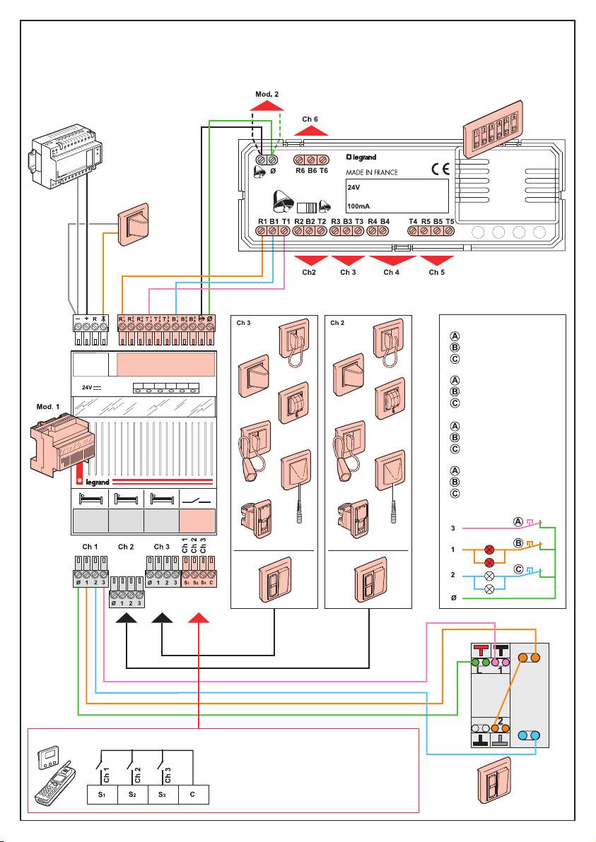
LEGRAND Mosaic 766 60 User manual

Ch 1 Ch 2 Ch 3
Ph
230v
NT
766 60
782 89
782 12
766 64
782 04
766 72
766 63 +
783 62
766 68 +
783 67
766 68 +
783 66
766 65 +
783 69
766 63 +
782 07
0,6 mm2
0,6 mm
2
0,6 mm2
1 mm2
•Appel infirmière Mosaic™
•Mosaic™nurse call unit
•Llamada enfermera Mosaic™
• Systém Sestra-Pacient –
Mosaic™
766 60 - 782 12
•Caractéristiques techniques
•Technical characteristics
•Características técnicas
•Technické charakteristiky
•Description
•Description
•Descripción
•Popis
•- Alimentation 24 V redressée filtrée
- Température de fonctionnement : -5 à + 40°C
- Séparer les circuits BTet TBTS.
•- Power supply 24 V
- Operating temperature : -5 to + 40 °C
- Separate the LV and SELV circuits.
•- Alimentación 24 V
- Temperatura de funcionamiento : de -5 a +40 °C
- Separar los circuitos BTy MBTS
•- Napájanie 24 V
- Prevádzková teplota: -5 a +40 °C
- Rozdeľte okruhy LV a SELV
LE00234AC
•Equipement salle infirmière
•Nurses’ station equipment
•Equipamiento de la sala de enfermeras
•Signalizačný panel
•Equipement armoire technique
•Technical enclosure quipment
•Equipamiento del cuadro
•Svorky riadiaceho modulu (782 12)
•Equipement chambres
•Room equipment
•Equipamiento de las habitaciones
•Vybavenie izieb
•Appel normal (1 Hz)
•Normal call (1 Hz)
•Llamada normal (1 Hz)
•Normálne volanie (1Hz)
•Appel d’urgence (0,5 Hz)
•Emergency call (0.5 Hz)
•Llamada de emergencia (0,5 Hz)
•Núdzové volanie (0,5Hz)
•Sorties contacts sec
•Volt-free contact outputs
•Salidas contactos secos
•Pomocné bezpotenciálové
kontakty

•Recherche de personnes, voyant, sonneries
•Locate nurse, indicator, audible signals
•Buscapersonas, piloto, timbres
•Signalizačné zariadenia: zvonček, signálky,
GSM brána
•Emergencia
Presencia
Llamada
•Núdzové volanie
Prítomnosť sestry
Pacientovo volanie
•Urgence
Présence
Appel
•Emergency
Present
Call
24 V 0,5 A
766 60
2
•Installation en fonctions minimum (exemple :raccordement chambre 1)
•Installation with minimum functions (example:connection to room 1)
•Instalación en funciones mínimas (ejemplo:conexiones de la habitación 1)
•Inštalácia so základnými funkciami (príklad: zapojenie 1 izby)
782 04

782 04
766 72
766 64
766 63
783 62
3
• Si pas de tirette faire shunt :
• If there is no pull cord : shunt
• Si no hay tirador efectuar un shunt
• V prípade, že nie je použitý
kúpeľňový modul : prepojte
• Si pas de poire d’appel faire shunt
• If there is no call button cord : shunt
• Si no hay pera de llamada efectuar
un shunt
• V prípade, že nie je použitý izbový
modul : prepojte
•Effectuer les mesures avant d’inserer les borniers sur le module 782 12
•Take measurements before inserting the terminal blocks on module Cat. No. 782 12
•Efectuar las mediciones antes de introducir los bornes en el módulo 782 12
•Pred vložením svoriek do modulu 782 12 premerajte parametre (viď strana č.6)
782 04
782 04

•Ø = masse
•24 R/Dc = raccordement inter modules
•R1, R2, R3, R4, R5, R6 = voyants rouges
•T1, T2, T3, T4, T5, T6 = poussoirs de tranquilisation
•B1, B2, B3, B4, B5, B6 = voyants blancs
•S1, S2, S3 = contacts sec relais
•C = Commun contacts sec relais
•= Sonnerie
•= Sortie voyant de synthèse
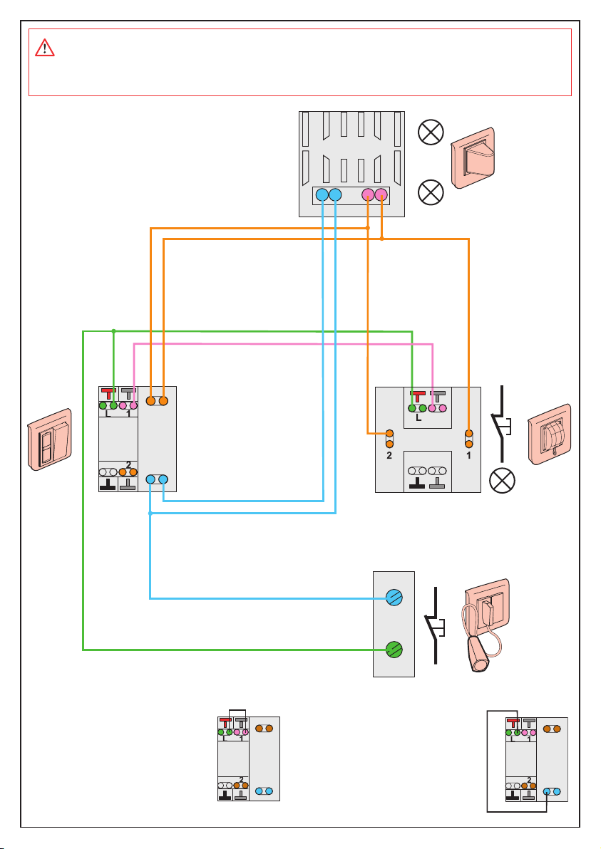
Attention :
Tous les poussoirs sont connectés en type :
contact NF (Normalement Fermé), sauf tranquilisa
tion contact NO (Normalement Ouvert).
•Ø = earth
•24 R/Dc = inter-module connection
•R1, R2, R3, R4, R5, R6 = red indicators
•T1, T2, T3, T4, T5, T6 = mute buttons
•B1, B2, B3, B4, B5, B6 = white indicators
•S1, S2, S3 = relay volt-free contacts
•C = Relay volt-free contacts common
•= Bell
•= Master indicator output
Caution :
All the pushbuttons are typically connected as follows:
NC contact (Normally Closed), apart from the mute NO
contact (Normally Open).
•Ø = Masa
•24 R/Dc = conexión entre módulos
•R1, R2, R3, R4, R5, R6 = pilotos rojos
•T1, T2, T3, T4, T5, T6 = pulsadores de tranquilización
•B1, B2, B3, B4, B5, B6 = pilotos blancos
•S1, S2, S3 = contactos secos de relé
•C = Común de los contactos secos de relé
•= Timbre
•= Salida del piloto general
Atención :
Los contactos de todos los pulsadores son de tipo:
normalmente cerrado, salvo el contacto de tranquili-
zación, que es de tipo normalmente abierto
•Ø = Zem
•24 R/Dc = napätie medzi prístrojmi
•R1, R2, R3, R4, R5, R6 = červené signálky
•T1, T2, T3, T4, T5, T6 = tlačidlá potvrdzujúce volanie
(na signalizačnom paneli, na dverovej jednotke...)
•B1, B2, B3, B4, B5, B6 = biele signálky
•S1, S2, S3 = pomocné bezpotenciálové kontakty
•C = zem (pre pomocné kontakty)
•= zvonček
•= hlavný signalizátor
Upozornenie: Všetky tlačítka sú normálne zapojené
nasledovne: konktakty NC (Normally Closed),
okrem tlačítok, ktorými sa potvrdzujú volania,
ktoré sú NO (Normally Open)
4
Consignes de sécurité
Ce produit doit être installé de préférence par un électricien qualifié. Une installation et une utilisation
incorrectes peuvent entraîner des risques de choc électrique ou d’incendie.
Avant d’effectuer l’installation, lire la notice, tenir compte du lieu de montage spécifique au produit.
Ne pas ouvrir l’appareil. Tous les produits Legrand doivent exclusivement être ouverts et réparés
par du personnel formé et habilité par LEGRAND. Toute ouverture ou réparation non autorisée
annule l’intégralité des responsabilités, droits à remplacement et garanties. Utiliser exclusivement les
accessoires d’origine.
Safety instructions
This product should be installed preferably by a qualified electrician. Incorrect installation and use can
entail risk of electric shock or fire.
Before carrying out the installation, read the instructions and take account of the product’s specific
mounting location.
Do not open up the device. All Legrand products must be exclusively opened and repaired by personnel
trained and approved by LEGRAND. Any unauthorised opening or repair completely cancels all liabilities
and the rights to replacement and guarantees. Only use genuine accessories.
Medidas de seguridad
Este producto debe ser instalado preferentemente por un instalador electricista cualificado. La instala-
ción y utilización incorrectas pueden generar riesgos de descargas eléctricas o de incendio.
Antes de efectuar la instalación, leer el manual y, tener en cuenta el lugar de montaje específico del
producto.
No abrir el aparato. Todos los productos Legrand deben ser abiertos y reparados exclusivamente
por personal formado y autorizado por Legrand. Cualquier apertura o reparación no autorizada anula
la integridad de las responsabilidades, derechos de cambio y garantías. Utilizar exclusivamente
accesorios originales.
Bezpečnostné nariadenia
Tento výrobok musí, podľa možností, inštalovať elektrikár, spĺňajúci kvalifikačné predpoklady, v súlade
sinštalačným návodom.
Pri nesprávnej inštalácii a pri nesprávnom používaní hrozí riziko úrazu elektrickým prúdom a riziko požiaru.
Pred uskutočnením inštalácie sa oboznámte s návodom a zohľadnite montážne miesto pre daný výrobok.
Prístroj neotvárajte, nerozoberajte, neupravujte ani nemodifukujte, iba ak by bolo v návode uvedené
inak. Všetky výrobky Legrand môže otvárať výlučne personál na to vyškolený a oprávnený spoločnosťou
Legrand. Akékoľvek neoprávnené otváranie alebo oprava rušia akúkoľvek zodpovednosť zo strany
Legrand, ako aj právo na výmenu výrobku a na záruku.
Používajte výlučne príslušenstvo značky Legrand.
FR LU BE
ES
GB I E
SK

Ch 6
Ch2 Ch 3 Ch 4 Ch 5
Ch 6
Ch2 Ch 3 Ch 4 Ch 5
Ch 6
Ch2 Ch 3 Ch 4 Ch 5
Ch 6
R4 B4 T4 R5 B5 T5
766 60
24V
100mA
R1 B1 T1 R2 B2 T2 R3 B3 T3
R6 B6 T6
Ø
R4 B4 T4 R5 B5 T5
766 60
24V
100mA
R1 B1 T1 R2 B2 T2 R3 B3 T3
R6 B6 T6
Ø
R4 B4 T4 R5 B5 T5
766 60
24V
100mA
R1 B1 T1 R2 B2 T2 R3 B3 T3
R6 B6 T6
Ø
R4 B4 T4 R5 B5 T5
766 60
24V
100mA
R1 B1 T1 R2 B2 T2 R3 B3 T3
R6 B6 T6
Ø
• Extention au-delà de 3 chambres (modules 782 12)
• Extension for more than 3 rooms (modules 782 12)
• Extensión a más de tres habitaciones (módulos 782 12)
• Rozšírenie systému pre viac ako 3 izby (moduly 782 12)
12
3 45
6 78
....
– +
R
– +
R
– +
R
1 mm
2
• Report d’appel sur autres afficheurs 782 13 (maxi 4)
• Call transfer to other display units (max.4)
• Traspaso de la llamada a otros paneles (4 máx.)
• Zobrazenie volania na dodatočných signalizačných
paneloch (max.4)
• Positionnement des étiquettes
• Inserting labels
• Colocación de las etiquetas
• Vloženie štítkov
5
• Voyant de synthèse (facultatif) maxi. 1
• Master indicator (optional) max. 1
• Piloto de síntesis (opcional) 1 máx.
• Hlavný signalizátor (voliteľné) max. 1

Ø123
Ω
Ω
2k
OFF
V/Ω
C M
25 < Ω < 2500
Ω =∞
Ω
ON
Ø123
Ω
Ω
2k
OFF
V/Ω
C M
25 < Ω < 2500
Ω =∞
Ω
ON
Ø123
Ω
Ω
2k
OFF
V/Ω
C M
0 < Ω < 500
Ω=∞
Ω
ON
A
C
B
Ø123
Ø123Ø123S1S2S3C
•Exemple :
test connecteur de chambre 1
•Example :
chamber 1 connector test
•Ejemplo :
test conector de habitación 1
•Príklad - test zapojenia izby č.1:
Na svorke izby č.1 zmerajte
nasledovné parametre
• Vérification avant mise en service
• Check before commissioning
• Verificación antes de la puesta en servicio
• Skontrolujte pred zapojením!
R
–
Ø
+R
1
4R2
5R3
6T1
4T2
5T3
6B1
4B2
5B3
6
24V
782 12 782 12
R
–Ø
+R1
4R2
5R3
6T1
4T2
5T3
6B1
4B2
5B3
6
24V
12
60
30
15
10
5
20
25
35
40
50
55
45
11
10
3
4
5
7
8
1
2
6
9
5s
•Réinitialisaton du module
•Module reset
• Reinicialización del módulo
• Reset systému
Upozornenie:
Ak zapojíte
svorku do ria-
diacej jednotky
bez premerania
parametrov,
môžete ju nená-
vratne poškodiť.
•Consignes de dépannage si défaut sur voyants
•What to do in case of indicator defect
• Consignas de reparación si los visores detectan defecto
• Čo robiť v prípade, že systém nefunguje
This manual suits for next models
1
Other LEGRAND Personal Care Product manuals