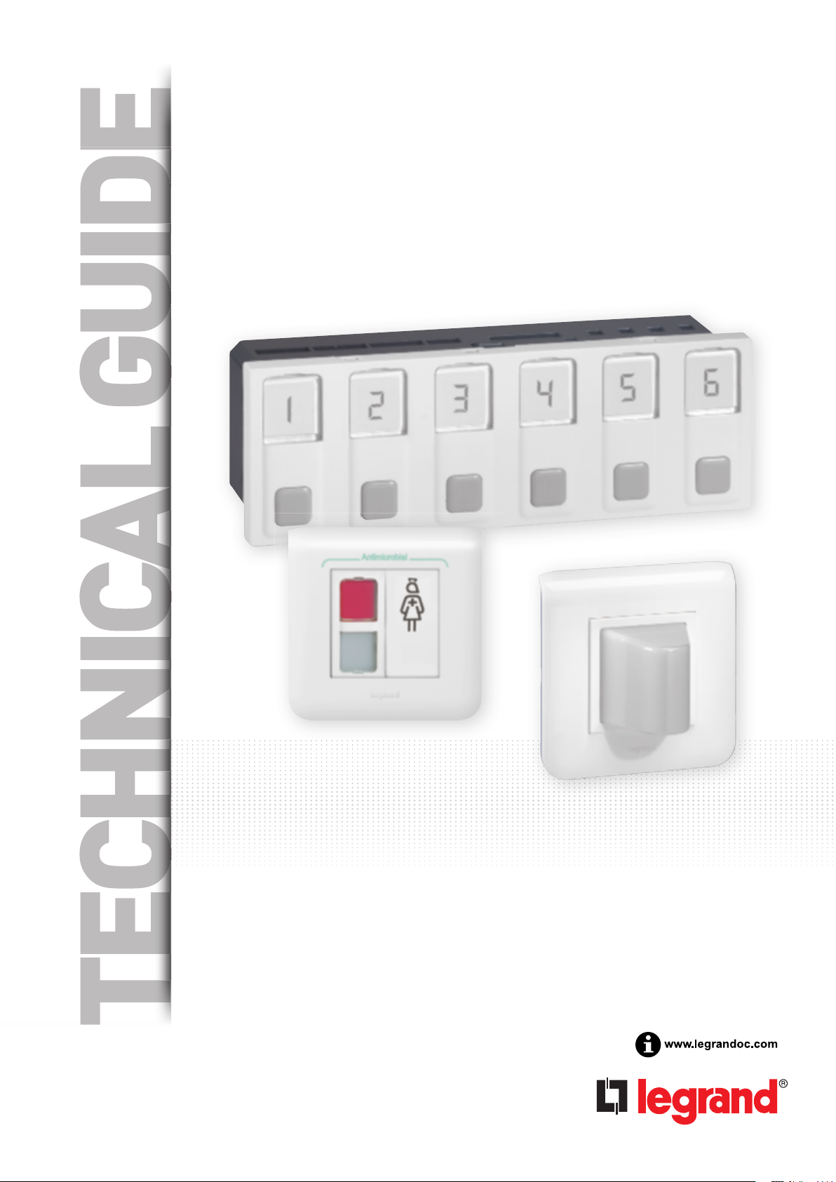
DESCRIP
OF
ARCHITEC
Fundamental rules
Patient call system
accordance with the
A single protection
To ensure continuous
mains failure longer
Note: The Mosaic nur
* Direction: room from
DESCRIPTION OF
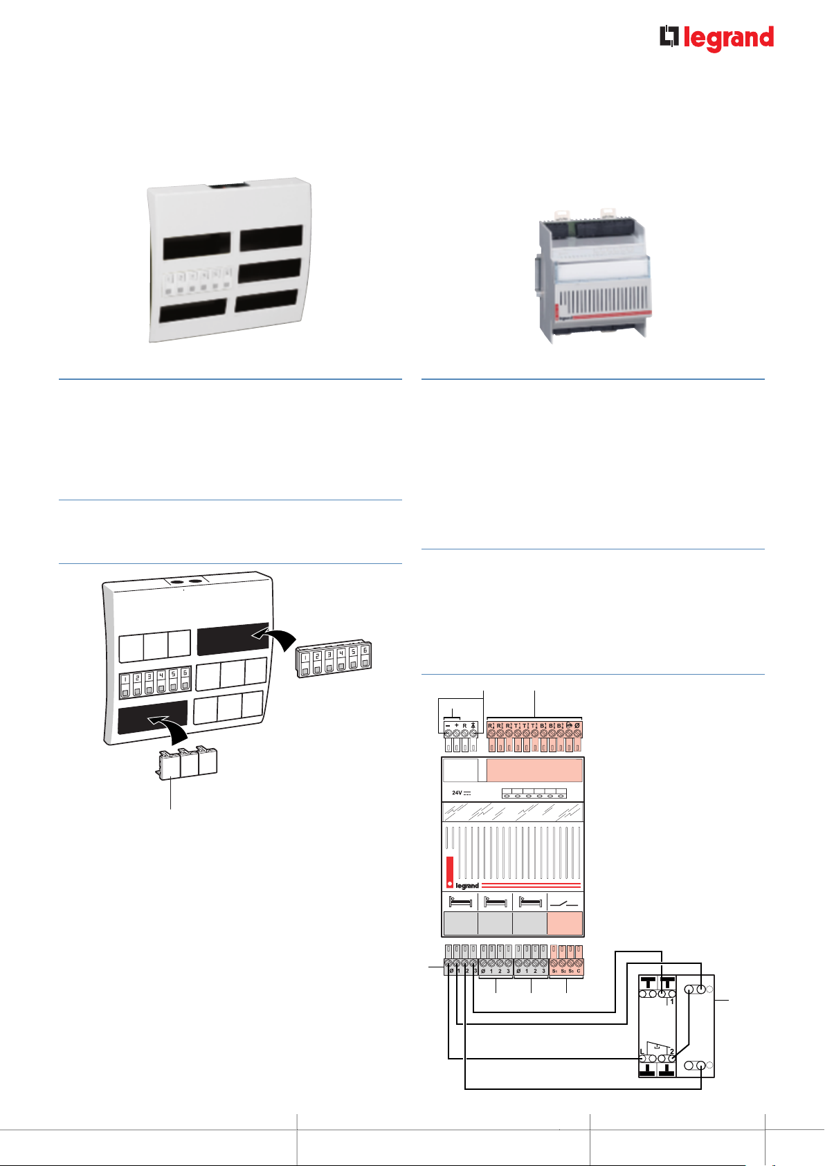
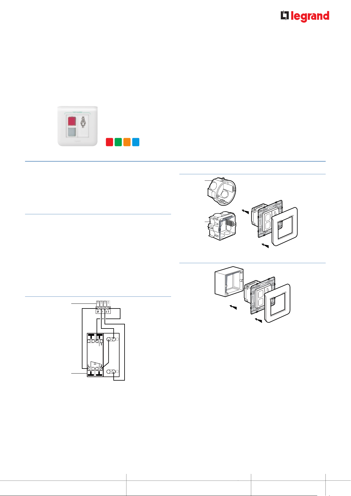
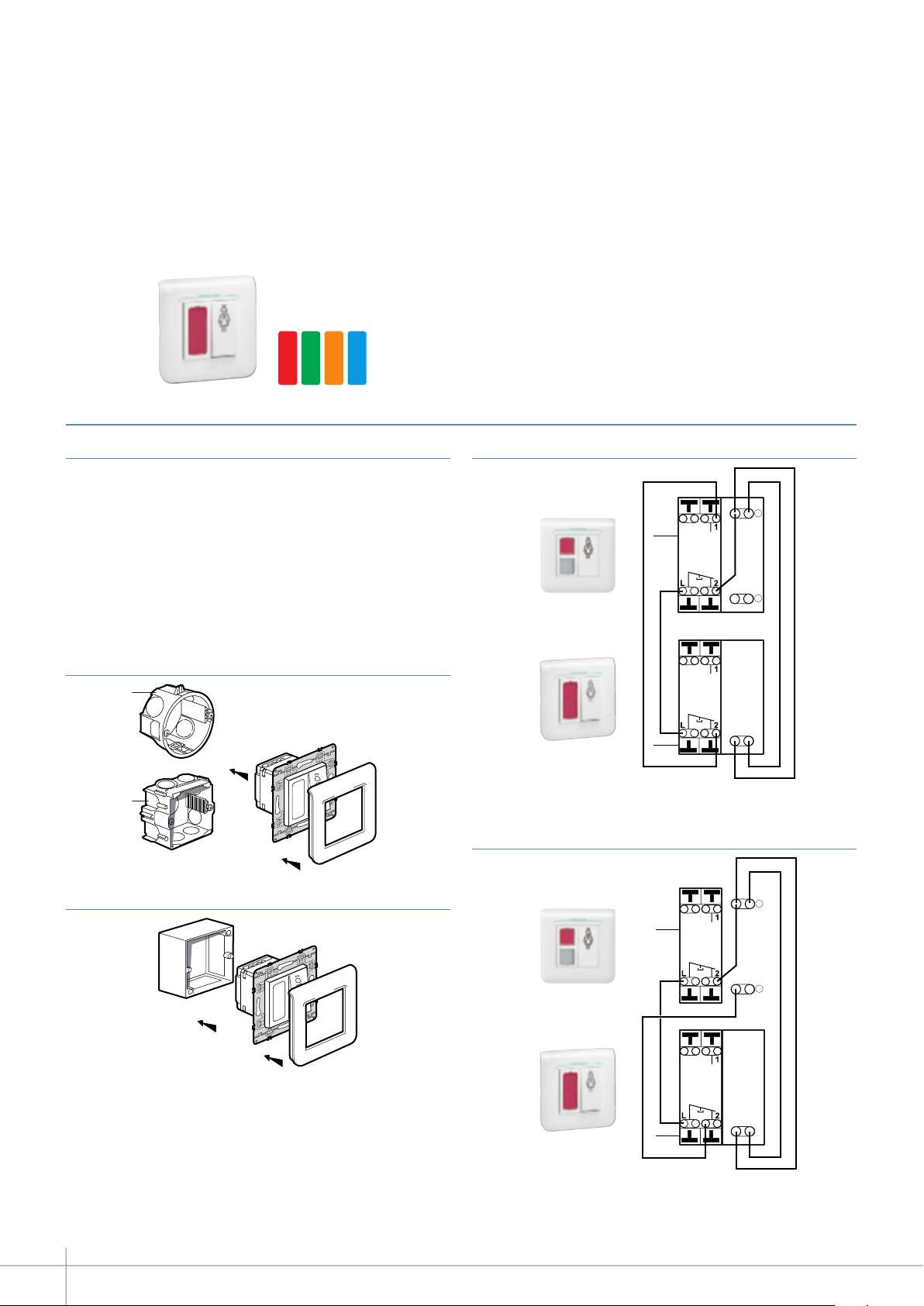
Wiring diagram
Contents
DESCRIPTION OF THE SYSTEM ARCHITECTURE >> 3
Fundamental rules to follow when installing the Mosaic
nurse call system >>>>>>>>>>>>>>>>>>>>>>3
Wiring diagram >>>>>>>>>>>>>>>>>>>>>>>3
Selection guide: how to draw up your list of equipment >>>4
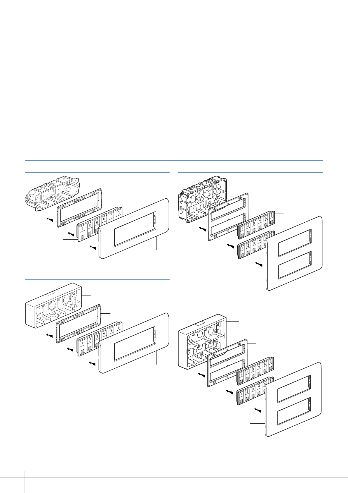
DEVICE PRESENTATION AND INSTALLATION >>>>>5
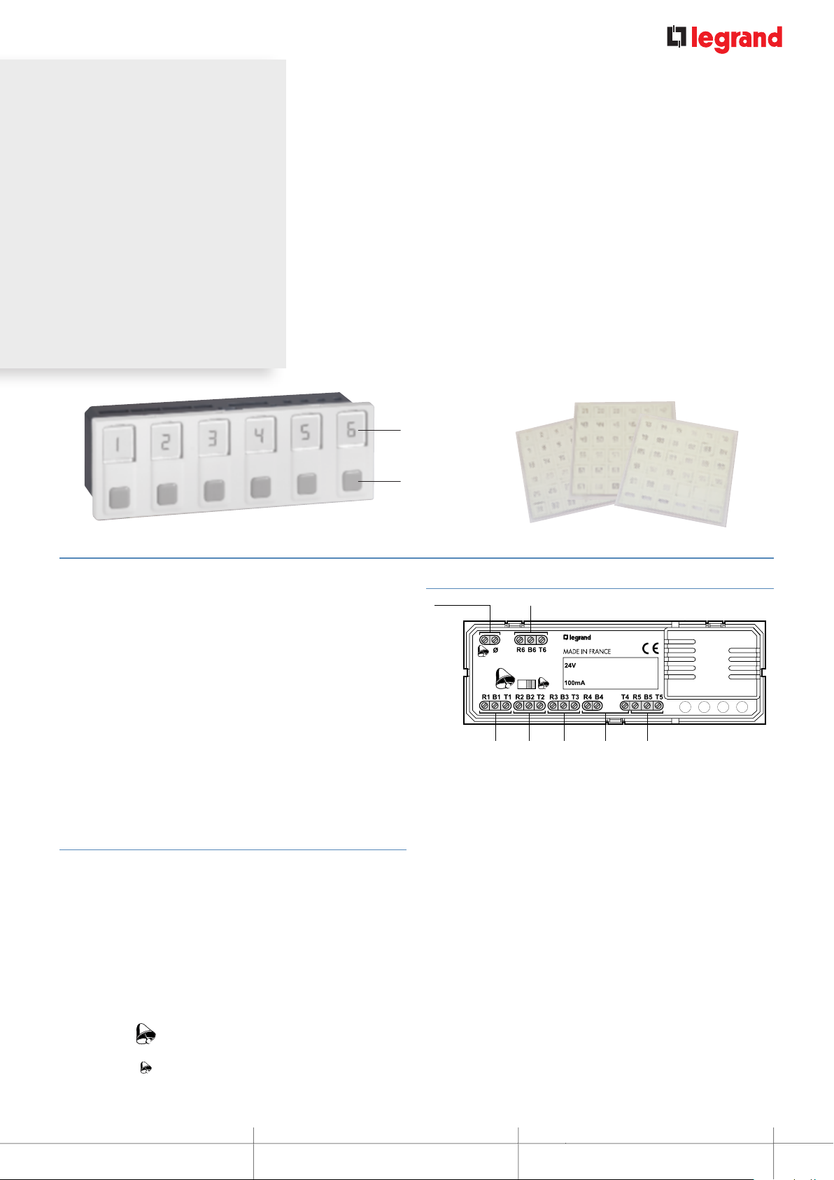
0 766 60: 6-direction call display unit>>>>>>>>>>>>>5
0 782 14: table control unit >>>>>>>>>>>>>>>>>>7
0 782 12: 3-direction management module >>>>>>>>>7
0 782 89: 24 V 2 A 48 W POWER SUPPLY >>>>>>>>>>8
0 035 67: auxiliary power supply >>>>>>>>>>>>>>>8
0 782 04: door unit >>>>>>>>>>>>>>>>>>>>>>9
0 766 85: bathroom call units or call button >>>>>>>> 10
0 766 63: socket for push-button cord >>>>>>>>>>> 11
0 783 62: push-button cord >>>>>>>>>>>>>>>> 11
077150+078207:biomedicalcallplugandsocket>>>> 12
0 782 43: clamp for push-button cord >>>>>>>>>>> 13
0 766 64: bathroom call pull-cord >>>>>>>>>>>>> 13
0 766 72: double display corridor overdoor light >>>>>> 14
0 766 71: call transfer light for corridors >>>>>>>>>> 15
0 766 42: electronic buzzer >>>>>>>>>>>>>>>>> 15
MOSAIC NURSE CALL UNIT >>>>>>>>>>>>>> 16
Call + nurse present >>>>>>>>>>>>>>>>>>>> 16
Bathroom call + nurse present>>>>>>>>>>>>>>> 17
Emergency call >>>>>>>>>>>>>>>>>>>>>> 18
Nurse present + call from another room >>>>>>>>>> 19
Nurse present + call from another bathroom >>>>>>> 20
Call priorities >>>>>>>>>>>>>>>>>>>>>>> 21
Wiring: call + presence installation for nursing homes
and residential homes for the elderly >>>>>>>>>>> 22
Wiring: call + presence installation with call via call button
and information transfer >>>>>>>>>>>>>>>>>> 24
Wiring: call + biomedical + presence installation with
DECT interface (integrated traceability) >>>>>>>>>> 26
COMMISSIONING >>>>>>>>>>>>>>>>>>>> 28
Check before switch-on >>>>>>>>>>>>>>>>>> 28
Resetting the module >>>>>>>>>>>>>>>>>>> 29
TROUBLESHOOTING >>>>>>>>>>>>>>>>>> 30
2
LE08358AB_EN.indd 2 22/06/2016 09:13