manuals.online logo
Brands
  1. Home
  2. •
  3. Brands
  4. •
  5. LEGRAND
  6. •
  7. Remote Control
  8. •
  9. LEGRAND DPX 1250 User manual

LEGRAND DPX 1250 User manual

1-Poignée de réarmement manuel
Manual reset lever
Leva riarmo manuale
Dźwignia ręcznego zazbrojenia
2-Indicateur ressort
Springs indicator
Indicatore molle
Wskaźnik stanu sprężyny
3-Poussoir de fermeture
Closing push button
Pulsante di chiusura
Przycisk załączenia
4-Poussoir d’ouverture
Opening push button
Pulsante di apertura
Przycisk wyłączenia
5-
Sélecteur du mode de fonctionnement
Mode selector
Selettore modalità di funzionamento
Przełącznik trybu pracy
A1
B2
C3
D1
E1
F1
G1
H1
I1
L1
M1
2
3P=210 4P=280
105
100
204
51
94
142
320
237
140 80 17
15
Y
Y
XX
1
7
4
52
6
1
3 8
FONCTIONNEMENT AUTOMATIQUE
AUTOMATIC OPERATION
FUNZIONAMENTO AUTOMATICO
AUTOMATYCZNY TRYB PRACY
-Ouverture avec commande sur
impulsion ou commande permanente ou bouton poussoir 4.
-Opening through single impulse or continuous control or push
buttons 4.
-Apertura con comando ad impulso o mantenuto o con i
pulsanti 4.
-Wyłączenie przez podanie impulsu lub ciągłego napięcia
sterującego oraz przycisk 4.
-Réarmement par moteur électrique ou avec la
poignée 1.
-Reset through the motor or with lever 1.
-Riarmo mediante motore elettrico o con la leva 1.
-Naciągnięcie sprężyny przez silnik lub dźwignię (1).
FONCTIONNEMENT MANUEL
MANUAL OPERATION
FUNZIONAMENTO MANUALE
RE˛CZNY TRYB PRACY
-Fermeture et ouverture exclusivement avec les poussoirs
(3 et 4).
-Closing and opening only through the push
bottons (3 - 4).
-
Chiusura e apertura esclusivamente tramite i pulsanti
(3 e 4).
-
Załączenie i wyłączenie tylko przez przyciski (3-4).
-Réarmement exclusivement avec la poignée (1).
-Reset only through the lever (1).
-
Riarmo esclusivamente con leva (1).
-
Naciągnięcie sprężyny tylko przez dźwignię (1).
ressort chargé
springs unloaded
molle scariche
sprężyna naciągnięta
ressort déchargé
springs loaded
molle cariche
sprężyna zwolniona
6-Indicateur de positions des contacts du disjoncteur:
Breaker contacts indicator:
Indicatore posizione contatti interruttore:
Wskaźnik stanu wyłącznika:
7-
Poignée pour cadenassage en position ouverte.
Padlock in open position.
Blocco lucchetti in posizione di aperto.
Blokada kłódką wyłączony.
8-
Indicateur disjoncteur dellenche.
Indicator MCCB tripped.
Indicatore interruttore scattato.
Wskaźnik wyzwolenia wyłącznika.
VÉROUILLAGE EN POSITION OUVERTE
LOCK IN OPEN POSITION
BLOCCO IN APERTO
BLOKADA W STANIE WYŁĄCZONYM
- Empêche toute manoeuvre.
- Stops any operation.
- Impedisce l’esecuzione di manovre.
-Blokad wszystkich operacji.
- Provoque le déclenchement du disjoncteur.
- Trips the breaker.
- Provoca lo sgancio dell’interruttore.
-Wyłączenie wyłącznika
N.B.: La poignée de cadenassage (7) doit être
enfoncée pour passer en fonction
"A
UT
/M
AN
".
A
TT
.: The padlock (7) have to be pushed inside to
get in “A
UT
/M
AN
”mode.
N.B.: Il blocco lucchetti (7) deve essere inserito
per avere abilitate le funzioni “A
UT
/M
AN
”.
U
WAGA
:Aby przejść w tryby pracy “A
UT
/M
AN
” należy
wcisnąć uchwyt dla kłódki (7).
RED
CZERWONY
GREEN
ZIELONY
fermé
=closed
chiusi
załączony
ouvert
=open
aperti
wyłączony
A
B
C
D
E
F
G
I
H
L
M
®
GF01/2007-01
NT 80071LG
•Commande motorisée
•Remote control
•Comando a motore
•Zdalne sterowanie
DPX 1250 DPX 1600
➊
➋
➋
➊
➌
➋
➍
➊
5
4
3
®
➊
12345678
➋
9
8
7
A
Pour positionner le levier,
recharger le ressort.
To set the lever, load
the spring.
Per posizionare la leva
caricare la molla.
Puruszając dźwignią
naciągnąć sprężynę.
10
D
L
E
F
Remonter le couvercle
du disjoncteur.
Mount the breaker’s
cover and plug the
device and the lever in.
Montare il coperchio
interruttore ed inserire
il blocchetto e la leva.
Zamontować pokrywę
wyłącznika oraz
akcesoria montażowe.
ø 5
ø 5
Retirer la fenêtre en plastique et perçer.
Take the frame out and drill the cover.
Togliere la mostrina e forare.
Usunąć ramkę, wywiercić otwory.
Perçer et éliminer les 2 diaphragmes.
Drill and cut the two small window.
Forare ed eliminare i due diaframmi.
Wywiercić otwory, usunąć zaślepki.
Retirer le couvercle
du disjoncteur et eliminer
les vis.
Dismount the small
breaker’s cover and
exclude the screws.
Togliere coperchio
interruttore e
coprimaniglia ed eliminare
le viti evidenziate.
Zdemontować pokrywę
przednią wyłącznika i
wykręcić wkręty.
Retirer le capot de la commande. Togliere la calotta motore.
Take the motor operator cover out.
Zdjąć osłonę sterowania.
N.B.: Positionner le sélecteur de mode
fonctionnement (5) sur la position MAN.
ATT.: Set the mode selector (5) on position MAN.
N.B.: Portare il selettore (5) modalità di funzionamento, sulla posizione MAN.
Uwaga: Ustawić przeł. trybów pracy (5) w pozycji MAN.
6
Coller l’étiquette.
Stick the label.
Applicare la tarfghetta
Nakleić etykietę.
➌
➋3
➊
➊
➊
15
12
11
➋
➊
Recherger le ressort
jusqu’à ce que la poignée
de bloque complétement.
Recharge the spring up
to the lock of the toggle
proceeding also when
the toggle is loadless.
Ricaricare la molla fino al
blocco della maniglia
continuando anche
quando la molla carica
a vuoto.
Naciągnąć sprężynę aż
do zwolnienie dźwigni.
16
C
C
C
G
M
Monter la base du moteur
sur le disjoncteur.
Mount the motor operator
base on the breaker.
Montare la base motore
sull’interruttore.
Zamontować zdalne
sterowanie na wyłączniku.
1 Nm
max
B
B
I
Visser le capot
du moteur.
Fix the motor
operator cover
screws.
Avvitare la
calotta motore.
Zamontować
osłone zdalnego
sterowania.
Declencher et tenir poussè.
Trip and keep pushed.
Sganciare e mantenere premuto.
Zwolnij i wciznij.
Deplacer le selecteur dans cadenas.
Shift selector on padlock.
Posizionare il selettore su blocco lucchetti.
Przetącz.
Montage cadenas.
Pad locks installation.
Installazione lucchetti.
Blokada kłódką.
➊➋
13
14
➊
4
➌
➋
➍
17
Montage chef pour
vérrouillage.
Key lock installation.
Installazione blocco chiave.
Montaż blokady kluczem.
Retirer le capot du moteur.
Take the motor operator cover out.
Togliere calotta motore.
Wyjąć zaślepkę z obudowy napędu.
Monter la chef.
Key lock installation.
Montare blocco a chiave.
Zainstalować zamek.
➊
➋
PUISSANCE ABSORBEE
INPUT POWER
POTENZA ASSORBITA
POBÓR MOCY
18
A,C: contacts NF; avec moteur en MANUAL coupent l’alimentation du moteur et de la bobine de
fermeture; ils s’ouvrent aussi si on enleve le couvercle du moteur, avec bloc à clè inserè ou
selecteur sur cadenas.
B,D: contact 1NF+1NO avec disjoncteur ouvert et ressort chargèes a la position de la figure. Avec
ressorts dechargèes fermes D et ouvres B.
E: contact de signalisation: segnale la position des contacts principal du disjoncteur: avec
disjoncteur ouvert il’y a continuitè entre les bornes 7-8.
A,C: contacts NC; with remote control on MAN cut electric supply
to motor and closing coil; open also when the cover is removed,
keylock fitted, selector on padlock.
B,D: contacts 1NC+1NO.With breaker open and spring charged
their state is like in picture.With springs discharged closes D and opens B.
E: signalling contact; signal the position of principal contacts of the breaker: with breaker open
there’s continuity between clamps 7 and 8.
A,C: contatti NC; con motore su MANUALE tagliano l’alimentazione del motore e della bobina di
chiusura; si aprono anche in caso di asportazione del coperchio motore, blocco a chiave inserito,
selettore su blocco lucchetto. B,D: contatto 1NC+1NO. Ad interruttore aperto e molle cariche ha lo
stato rappresentato in figura. A molle scariche chiude D e apre B.
E: contatto di segnalazione: segnala la posizione dei contatti principali dell’interruttore: ad
interruttore aperto c’è continuità fra i morsetti 7-8.
A,C: styki NC; przy wyborze trybu pracy MAN odcinają zasilanie dla napędu silnikowego oraz
cewki załączającej; otwarte gdy osłona napędu jest zdjęta oraz przy blokadzie kłódką lub
zamkiem.
B,D: styki 1NC+1NO. Pozycja styków jak na rysunku przy wyłączonym wyłączniku oraz
naciągniętej sprężynie. Po zwolnieniu sprężyny styki zmieniają pozycję.
E: styk sygnalizacyjny położenia styków głównych wyłącznika. Styk zwarty przy wyłączonym
wyłączniku.
BC: Bobine de fermeture
Closing coil
Bobina di chiusura
Cewka załączająca
M: Moteur
Motor operator
Motore
Napęd silnikowy
LGR026154\.. avec borneur / with lug / con morsettiera / z kostką zaciskową
A
B
C
D
E
MAN
Q1
BC M
2 4 6 8
1 3 5 7
ferme
close
chiude
załączony
ouvre
open
apre
wyłączony
C
A
B
C
D
E
MAN
Q1
BC M
2 4 6 8
1 3 5 7
A
B
C
D
E
MAN
Q1
BC M
2 4 6 8
1 3 5 7
C2
Bk
C1
Bk
S2S1
Command mantenu.
Switch operated.
Comando mantenuto.
Sterowanie łącznikiem 3
pozycyjnym.
Recharge volontaire
Volontary reset
Ricarica volontaria.
Ręczne zazbrojenie.
Commande impulsif.
Pushbotton operated.
Comando impulsivo .
Sterowanie przyciskami.
Recharge automatique depuis
declenchement.
Automatic reset after tripping.
Ricarica automatica dopo
sgancio.
Automatyczne zazbrojenie.
Accessoirement avec bobine
à emission.
Fitting with shunt trip.
Accessoriamento con bobina
a lancio.
Wyłączenie przez wyzwalacz
wzrostowv.
CARACTERISTIQUES / TECHNICAL CHARACTERISTICS / CARATTERISTICHE TECNICHE / PARAMETRY TECHNICZNE
TENSION
VOLTAGE
TENSIONE
NAPIE˛CIE
TEMPS D’OUVERTURE ET
REARMEMENT
OPENING AND RESET TIME
TEMPO APERTURA E RIPRISTINO
CZAS WYŁĄCZENIA + ZAZBROJENIE
TEMPS DE
FERMETURE
CLOSING TIME
TEMPO CHIUSURA
CZAS ZAŁĄCZENIA
[W/VA]
demerrage / start
spunto / rozruch
régime / steady state
regime / stan ustalony
24V dc
48V dc
24V ac
48V ac
110V ac
230V ac
460 160 6 sec ≤100 ms
BORNE A CAGE / LUG
MORSETTO / ZACISK
FONCTION / FUNCTION / FUNZIONE / FUNKCJA
1
2
3
4
5
6
7
8
Alimentation fermeture / Closing power supply / Alimentazione di chiusura / Załączenie
Alimentation overture / Opening power supply / Alimentazione di apertura / Wyłączenie
NO (250 Vac/2A) Resort chargé / Spring open / Molle cariche / Sprężyna zwolniona
NC (250 Vac/2A)
Distoncteur ouver / MCCB open / Interruttore aperto / Wyłącznik wyłączony
UTILISATION EN INVERSEURS DE SOURCE AUTOMATIQUES
Attention:
selon la modalitè d’utilisation du moteur, c’est a direi:
•Sans declencheur
ou
•Avec declencheur (26164-8;26181-4)
Le temp de commutation entre ligne principale et ligne secovrue
(temps entre l’ouverture du disjoncteur de la ligne pricipale et la
fermeture de celui de la secours) doit entre enregistrè de fason que
sait superieur ou egal respectivement à:
•6sec
ou
•0,5 sec
USE FOR AUTOMATIC CHANGEOVER
Caution: according to the use mode of the motor that is:
•without tripping device
or
•with tripping device (26164-8;26181-4)
The changeover time between main and secondary line (time
between the opening of the breakers of the main line and the
closing of the breakers of the secondary line and viceversa) should
be setted at a value bigger or equal respectively to:
•6sec
or
•0,5 sec

Other manuals for DPX 1250

1

This manual suits for next models

3

Other LEGRAND Remote Control manuals

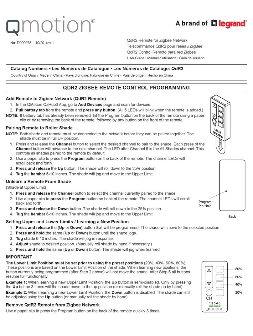
LEGRAND Qmotion QDR2 User manual

LEGRAND

LEGRAND Qmotion QDR2 User manual

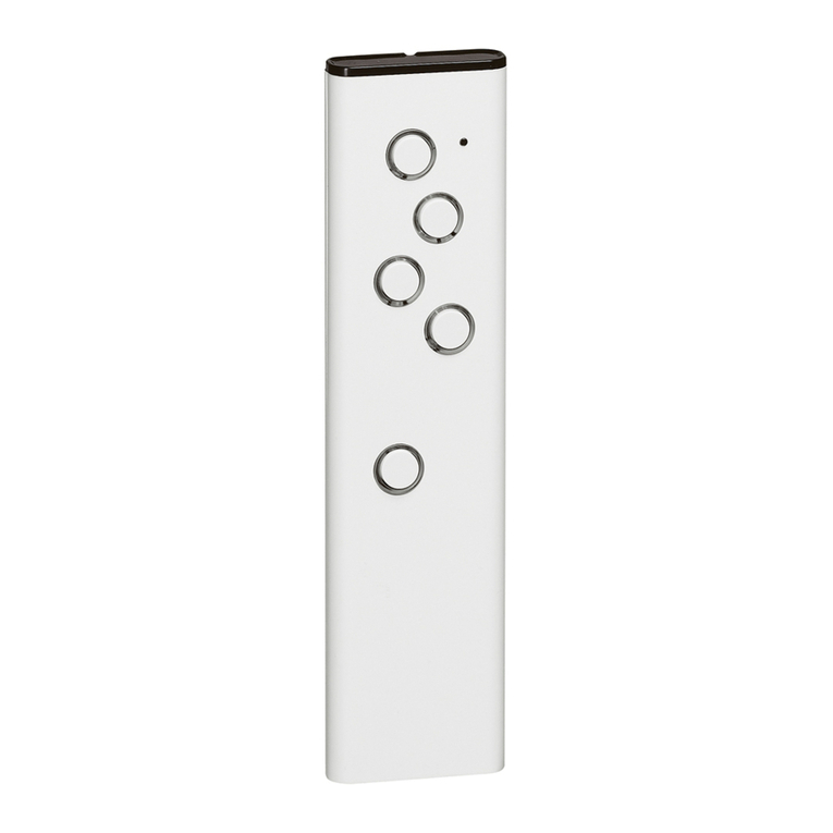
LEGRAND ADMHRM4 User manual

LEGRAND

LEGRAND ADMHRM4 User manual

LEGRAND Qmotion QDR2 User manual

LEGRAND

LEGRAND Qmotion QDR2 User manual

LEGRAND FB Advanced User manual

LEGRAND

LEGRAND FB Advanced User manual

LEGRAND 067695 User manual

LEGRAND

LEGRAND 067695 User manual

LEGRAND DPX 250 User manual

LEGRAND

LEGRAND DPX 250 User manual

LEGRAND 882 32 User manual

LEGRAND

LEGRAND 882 32 User manual

LEGRAND 5 738 70 User manual

LEGRAND

LEGRAND 5 738 70 User manual

LEGRAND Wattstopper LMRH-105 User manual

LEGRAND

LEGRAND Wattstopper LMRH-105 User manual

LEGRAND 882 32 User manual

LEGRAND

LEGRAND 882 32 User manual

LEGRAND 0 672 64 User manual

LEGRAND

LEGRAND 0 672 64 User manual

LEGRAND 882 30 User manual

LEGRAND

LEGRAND 882 30 User manual

LEGRAND DPX 250 User manual

LEGRAND

LEGRAND DPX 250 User manual

LEGRAND FB Advanced Instruction manual

LEGRAND

LEGRAND FB Advanced Instruction manual

LEGRAND 348220 User manual

LEGRAND

LEGRAND 348220 User manual

LEGRAND VADDIO HuddleSHOT Remote User manual

LEGRAND

LEGRAND VADDIO HuddleSHOT Remote User manual

LEGRAND Pass & Seymour LightSense PSWRR User manual

LEGRAND

LEGRAND Pass & Seymour LightSense PSWRR User manual

LEGRAND 0 883 07 User manual

LEGRAND

LEGRAND 0 883 07 User manual

LEGRAND 0 676 95 User manual

LEGRAND

LEGRAND 0 676 95 User manual

LEGRAND 0 882 32 User manual

LEGRAND

LEGRAND 0 882 32 User manual

LEGRAND QMotion Installation manual

LEGRAND

LEGRAND QMotion Installation manual

LEGRAND RCFREMOTE User manual

LEGRAND

LEGRAND RCFREMOTE User manual

LEGRAND Vaddio RF User manual

LEGRAND

LEGRAND Vaddio RF User manual

LEGRAND 0 698 73L User manual

LEGRAND

LEGRAND 0 698 73L User manual

Popular Remote Control manuals by other brands

Total Control URC - 2082 manual

Total Control

Total Control URC - 2082 manual

FUTABA S.BUS2 10J instruction manual

FUTABA

FUTABA S.BUS2 10J instruction manual

Teleco BST7 quick start guide

Teleco

Teleco BST7 quick start guide

Walkera DEVO-F12E(WHITE) Setup instructions

Walkera

Walkera DEVO-F12E(WHITE) Setup instructions

Hunter 99770 installation guide

Hunter

Hunter 99770 installation guide

Euroheat IN1174 operating instructions

Euroheat

Euroheat IN1174 operating instructions

THOMSON 510050 quick start guide

THOMSON

THOMSON 510050 quick start guide

Grohe Blue Home 36 407 operating instructions

Grohe

Grohe Blue Home 36 407 operating instructions

JMA BT MULTI USER PRO user manual

JMA

JMA BT MULTI USER PRO user manual

NEEWER RC-2 user manual

NEEWER

NEEWER RC-2 user manual

LEXIBOOK ST5 manual

LEXIBOOK

LEXIBOOK ST5 manual

SOMFY Impresario Chronis RTS user manual

SOMFY

SOMFY Impresario Chronis RTS user manual

Sony RCP-D50 operating instructions

Sony

Sony RCP-D50 operating instructions

Namsung RF30 user manual

Namsung

Namsung RF30 user manual

Topens M12 user manual

Topens

Topens M12 user manual

Wibre 5.0690.09.55 installation manual

Wibre

Wibre 5.0690.09.55 installation manual

Sony RM-TP503 operating instructions

Sony

Sony RM-TP503 operating instructions

Mitsubishi Electric PAR-SL100A-E Operation manual

Mitsubishi Electric

Mitsubishi Electric PAR-SL100A-E Operation manual

manuals.online logo
manuals.online logoBrands
  • About & Mission
  • Contact us
  • Privacy Policy
  • Terms and Conditions

Copyright 2025 Manuals.Online. All Rights Reserved.