manuals.online logo
Brands
  1. Home
  2. •
  3. Brands
  4. •
  5. LEGRAND
  6. •
  7. Remote Control
  8. •
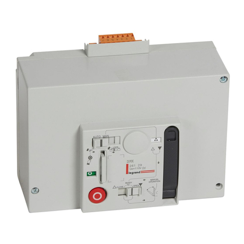
  9. LEGRAND DPX 250 User manual

LEGRAND DPX 250 User manual

FONCTIONNEMENT AUTOMATIQUE
AUTOMATIC OPERATION
AUTOMATYCZNY TRYB PRACY
- Ouverture avec commande sur impulsion ou commande
permanente ou bouton poussoir 4.
- Opening through single impulse or continuous control or push
button 4.
- Wyłączenie przez podanie impulsu lub ciągłego napięcia
sterującego oraz przycisk 4.
- Fermeture seulement avec commande électrique (sur
impulsion ou commande permanente).
- Electrical closing operation only (through impulsive or
continuous control).
- Załączenie tylko zdalnie, przez podanie impulsu lub
ciągłego napięcia sterującego.
1
2 3 4 5 6 7 8 9
10
11 12 13 14 15 16
17
18 19
20
4a 4b
21 22 23 24 25 26
1
2
3 4 5 6 7 8 9
10
11 12 13 14 15 16
17
18 19
20
4a 4b
21 22 23 24 25 26
12345678
A 1
B 2
C 2
D 1
E 1
F 1
G 2
Y
X
52,5
200
198
105 80 13
122
142
51
X
94
3P=105 - 4P=140
100
Y
15
123,5
1
2 3 4 5 6 7 8 9
10
11 12 13 14 15 16
17
18 19
20
4a 4b
21 22 23 24 25 26
I
7
64
5 3 2 1
1 - Poignée de réarmement manuel
Manual reset lever /
Dźwignia ręcznego zazbrojenia
2 - Indicateur ressort
Springs indicator / Wskaźnik stanu spręźyny
3 - Poussoir de fermeture / Closing push button
Przycisk załączenia
4 - Poussoir d’ouverture / Opening push button
Przycisk wyłączenia
5 - Sélecteur du mode de fonctionnement
Mode selector / Przełącznik trybu pracy
ressort déchargé / springs loaded / sprężyna zwolniona
ressort chargé / springs unloaded / sprężyna naciągnięta
DISCHARGED
CHARGED
➊
➌
➍
➋
1 2
3
4 5 6 7 8 9
10
11 12 13 14 15 16
17
18 19
20
4a 4b
21 22 23 24 25 26
Retirer le couvercle du disjoncteur et enlever les vis
(•).
Dismount the small breaker’s cover and exclude the
screws (•).
Zdemontować pokrywę przednią wy
łą
cznika i wykręcić
wkręty (•).
4P 3P
FONCTIONNEMENT MANUEL
MANUAL OPERATION
RĘCZNY TRYB PRACY
-
Fermeture et ouverture exclusivement avec les poussoirs (3 et 4).
- Closing and opening only through the push bottons (3 - 4).
-
Załączenie i wyłączenie tylko przez przyciski (3-4).
- Réarmement exclusivement avec la poignée (1).
- Reset only through the lever (1).
-
Naciągnięcie sprężyny tylko przez dźwignię (1).
N.B.: Le capot de la commande ne doit pas être
remonté dans ce mode de fonctionnement.
ATT.: The cover shield must not be removed in this
operation mode.
Uwaga: Osłona napędu nie może być zdjęta.
VERROUILLAGE EN POSITION OUVERTE
LOCK IN OPEN POSITION
BLOKADA W STANIE WYŁĄCZONYM
- Empêche toute manoeuvre.
- Stops any operation.
- Blokad wszystkich operacji.
- Provoque le déclenchement du disjoncteur.
- Trips the breaker.
- Wyłączenie wyłącznika
N.B.: La poignée de cadenassage (13) doit être
enfoncée pour passer en fonction “Aut/MAn”.
Att.: The padlock (13) have to be pushed inside to get in
“Aut/MAn” mode.
UwAgA: Aby przejść w tryby pracy “Aut/MAn” należy
wcisnąć uchwyt dla kłódki (13).
6 - Indicateur de positions des contacts du disjoncteur:
Breaker contacts indicator:
Wskaźnik stanu wyłącznika:
7 -
Poignée pour cadenassage en position ouverte.
Padlock in open position.
Blokada kłódką wyłączony.
RED
CZERWONY
GREEN
ZIELONY
RED
CZERWONY
GREEN
ZIELONY
fermé
= closed
załączony
ouvert
= open
wyłączony
- Réarmement par moteur électrique ou avec la poignée 1.
- Reset through the motor or with lever 1.
-
Naciągnięcie sprężyny przez silnik lub dźwignię (1).
Y3217C
GF06/201301
®
• Commande motorisée
• Remote control
• Zdalne sterowanie
DPX 250
A
B C D
E
F
G

2
➊
➋
➌
®
1 2 3 4 5 6
7
8 9
10
11 12 13 14 15 16
17
18 19
20
4a 4b
21 22 23 24 25 26
1 2 3
4
5 6 7 8 9
10
11 12 13 14 15 16
17
18 19
20
4a 4b
21 22 23 24 25 26
➋
➊
1 2 3 4 5 6 7
8
9
10
11 12 13 14 15 16
17
18 19
20
4a 4b
21 22 23 24 25 26
®
1 2 3 4 5
6
7 8 9
10
11 12 13 14 15 16
17
18 19
20
4a 4b
21 22 23 24 25 26
D
Coller l’étiquette.
Stick the label.
Nakleić etykietę.
Retirer le capot de la commande.
Take the motor operator cover out.
Zdjąć osłonę sterowania.
N.B.: Positionner le sélecteur
de mode fonctionnement (5)
sur la position MAN.
ATT.: Set the mode selector (5)
on position MAN
Uwaga: Ustawić przeł. trybów
pracy (5) w pozycji MAN.
1 2 3 4 5 6 7 8 9
10
11 12 13 14 15 16
17
18 19
20
4a 4b
21 22 23 24 25 26
B
C
B
Monter la base de la
commande à distance
sur le disjoncteur.
Mount the motor operator
base on the breaker.
Zamontować zdalne
sterowanie na wyłączniku.
2 Nm
12345678
E
Visser le capot de la
commande à distance.
Fix the motor operator
cover screws.
Zamontować osłonę
zdalnego sterowania.
1 2 3 4 5 6 7 8 9
10
11
12 13 14 15 16
17
18 19
20
4a 4b
21 22 23 24 25 26
1 Nm
1 2 3 4
5
6 7 8 9
10
11 12 13 14 15 16
17
18 19
20
4a 4b
21 22 23 24 25 26
ø 4,5 mm
ø 3 mm
Percer la capot.
Drill the cover.
Wywiercić otwory w pokrywie.
➊
➌
➋C C
B B
C C
B B
1 2 3 4 5 6 7 8
9
10
11 12 13 14 15 16
17
18 19
20
4a 4b
21 22 23 24 25 26
Remonter le couvercle du disjoncteur.
Mount the small breaker’s cover.
Zamontować pokrywę wyłącznika.
4P 3P
Enlever la capot
➊
en plastique, retirer le premier
diaphragm
e
➋
et retirer la petite fenêtre
➌
.
Take the frame out
➊
, cut the screen
➋
and exclude
the small window
➌
.
Usunąć pokrywę
➊
,
usunąć osłone
➋
,
wyłamać okno
➌
.
3
➋
➊
➊
12345678
➋
3
12345678
12345678
➋
➊
➊
12345678
➋
3
12345678
12345678
1 2 3 4 5 6 7 8 9
10
11 12 13
14
15 16
17
18 19
20
4a 4b
21 22 23 24 25 26
1 2 3 4 5 6 7 8 9
10
11
12
13 14 15 16
17
18 19
20
4a 4b
21 22 23 24 25 26
Déclencher
et pousser
(1).
Déplacer le
selecteur (2).
Cadenasser (3)
Trip and push
(1).
Shift selector (2).
Lock (3)
Zwolnij i wciznij
(1)
.
Przetącz
(2).
Blokada (3)
1 2 3 4 5 6 7 8 9
10
11 12 13 14 15
16
17
18 19
20
4a 4b
21 22 23 24 25 26
BC
LEGENDE DES COULEURS / COLOUR TABLE:
Bk: Noir / Black / Czarny Wh: Blanc / White / Bia≥y Rd: Rouge / Red / Czerwony Bl: Bleu / Blue / Niebieski
(i)
Relais 2 N.O. (Ref. 04049)
Release 2 N.O.
Stycznik 2NO
Bobine de fermeture
Closing coil
Cewka załączająca
M
Q1
Disjoncteur ou interrupteur
Automatic C.B. or isolator
Wyłącznik lub rozłącznik mocy
Commande à distance
Motor operator
Napęd silnikowy
S2
Poussoir d’ouverture / réarmement
Opening / trip push button
Przycisk "WYŁĄCZ/ZAZBRÓJ"
Contacts protection couvercle
Contacts for cover’s protection
Styki, zabiecz. po zdjęciu osłony
Commande à came-signal de ressort chargé
Cam control - spring loaded indication
Mechanizm krzywkowy - sygnalizacja zazbrojenia
D
Contact auxiliaire disjoncteur
Auxiliary contact MCCB (Ref. 26160)
Styk pomocniczy DPX
E
Contact auxiliaire disjoncteur
Auxiliary contact MCCB (Ref. 26160)
Styk pomocniczy DPX
S1
(ii)
Poussoir N.O. (Ref. 04453)
Release N.O.
Stycznik 1NO
Poussoir de fermeture
Closing push button
Przycisk "ZAŁĄCZ"
SE
Contact qui permet le réarmement
volontaire.
Contact for volontary reset
Styk dla ręcznego zazbrojenia
➋
➊
➊
12345678
➋
3
12345678
12345678
N° 3 max ø 6 mm
26158 Profalux
26159 Ronix
➋
➊
➊
12345678
➋
3
12345678
12345678
Rétablissement fonction AUTO/MAN.
AUTO/MAN operation reset.
Przejście do trybów pracy AUTO/MAN.
1 2 3 4 5 6 7 8 9
10
11 12
13
14 15 16
17
18 19
20
4a 4b
21 22 23 24 25 26
➋
➊
➊
12345678
➋
3
12345678
12345678
G
12345678
F
Y
Y
45
54
3
20,5
A < 23
12,5
ø 3,5
1 2 3 4 5 6 7 8 9
10
11 12 13 14
15
16
17
18 19
20
4a 4b
21 22 23 24 25 26
XL3
4
CARACTERISTIQUES / TECHNICAL CHARACTERISTICS / PARAMETRY TECHNICZNE
TEMPS D’OUVERTURE TOTAL + REARMEMENT
TOTAL OPENING TIME + RESET
CZAS WYŁĄCZENIA + ZAZBROJENIE
TEMPS DE FERMETURE
CLOSING TIME
CZAS ZAŁĄCZENIA
PUISSANCE ABSORBEE
START INPUT POWER
POBÓR MOCY
TENSION
VOLTAGE
NAPIĘCIE
24V cc
48V cc
24V ca
48V ca
110V ca
230V ca
2 s
2 s ≤ 100 ms
300 VA
≤ 100 ms300 W
S1
(ii)
(ii)
(i)
S2
31 5 7
4 6 8
A
B
C
D
M
Q1
MAN
BC
2
S1
(ii)
(ii)
(i)
S2
31 5 7
4 6 8
A
B
C
D
M
Q1
MAN
BC
2
2414
Wh
Wh
22
12
Rd
Rd
Bk
Bk
2111
E
D
31 5 7
4 6 8
A
B
C
D
M
Q1
MAN
BC
2
C1
SE
S1
(ii)
(ii)
(i)
S2
31 5 7
4 6 8
A
B
C
D
M
Q1
MAN
BC
2
S1
(ii)
(ii)
(i)
S2
31 5 7
4 6 8
A
B
C
D
M
Q1
MAN
BC
2
2414
Wh
Wh
22
12
Rd
Rd
Bk
Bk
2111
E
D
31 5 7
4 6 8
A
B
C
D
M
Q1
MAN
BC
2
C1
SE
S1
(ii)
(ii)
(i)
S2
31 5 7
4 6 8
A
B
C
D
M
Q1
MAN
BC
2
S1
(ii)
(ii)
(i)
S2
31 5 7
4 6 8
A
B
C
D
M
Q1
MAN
BC
2
2414
Wh
Wh
22
12
Rd
Rd
Bk
Bk
2111
E
D
31 5 7
4 6 8
A
B
C
D
M
Q1
MAN
BC
2
C1
SE
N.B.: Les schémas correspondent au disjoncteur en position ouverte et ressort du moteur chargé.
Att.: In the figures the C.B. is represented in open position, with spring’s motor loaded.
Uwaga: Pozycje styków wewnątrz napędu pokazano przy wyłączonym wyłączniku i naciągniętej sprężynie.
UTILISATION EN INVERSEURS
DE SOURCE AUTOMATIQUES
Attention:
selon la modalité
d’utilisation du moteur,
c’est a dire:
• Sans déclencheur
ou
• Avec déclencheur
(26164-8;26181-4)
Le temps de commutation
entre ligne principale et
ligne secourue (temps entre
l’ouverture du disjoncteur
de la ligne principale et la
fermeture de celle de secours)
doit être enregistré de façon
à être supérieur ou égal
respectivement à :
• 6 sec
ou
• 0,5 sec
USE FOR AUTOMATIC
CHANGEOVER
Caution:
according to the use mode
of the motor that is:
• without tripping device
or
• with tripping device
(26164-8;26181-4)
The changeover time between
main and secondary line (time
between the opening of the
breakers of the main line and
the closing of the breakers of the
secondary line and viceversa)
should be setted at a value
bigger or equal respectively to:
• 6 sec
or
• 0,5 sec
WSKAZANIA DLA ZMIANY
AUTOMATYCZNEJ
Uwaga:
Zgodnie z trybem
użytkowania silnika:
• Z wyłącznikiem
lub
• Bez wyłącznika
( 26164-8;26181-4)
Czas zmiany pomiędzy linią
główną, a linią dodatkową
(czas pomiędzy otwarciem
strumienia na linii głównej a
zamknięciem strumienia na
linii dodatkowej i odwrotnie)
powinien zostać ustawiony
na poziomie większym lub
równym:
• 6sekund
Lub
• 0,5 sekundy
Commande maintenue / Switch Operated
Sterowanie za pomocą łącznika 3 pozycyjnego
Réarmement volontaire / Volontary reset / Ręczne zazbrojenie
Fermeture
Closing
Załącz
Ouverture et charge
Open and charge
Wyłącz / Zazbrój
Commande à impulsion / Push button Operated
Sterowanie za pomocą przycisków
Réarmement automatique après déclenchement / Automatic reset after trip
Automatyczne zazbrojenie napędu po wyzwoleniu wyłącznika
Ferme
Closing
Załącz
Ferme
Closing
Załącz
Ouverture et charge
Open and charge
Wyłącz / Zazbrój
Ouverture et charge
Open and charge
Wyłącz / Zazbrój
Commande à impulsion / Push button Operated
Sterowanie za pomocą przycisków
Réarmement volontaire / Volontary reset / Ręczne zazbrojenie
BORNE A CAGE / LUG
ZACISK KLATKOWY
FONCTION / FUNCTION
FUNKCJA
1Alimentation fermeture / Closing power
supply / Załączanie źródła zasilania
2
3Alimentation ouverture / Opening power
supply / Odłączanie źródła zasilania
4
5NO (250
Vac/2A)
Ressort chargé / Spring loaded
/ Sprężyna naciągnięta
6
7Pas connectés / Not connected /
Nie podłączone
8

Other LEGRAND Remote Control manuals

LEGRAND 882 32 User manual

LEGRAND

LEGRAND 882 32 User manual

LEGRAND Qmotion QDR2 User manual

LEGRAND

LEGRAND Qmotion QDR2 User manual

LEGRAND Wattstopper LMRH-101 User manual

LEGRAND

LEGRAND Wattstopper LMRH-101 User manual

LEGRAND 882 32 User manual

LEGRAND

LEGRAND 882 32 User manual

LEGRAND In One 882 00 User manual

LEGRAND

LEGRAND In One 882 00 User manual

LEGRAND Pass & Seymour LightSense PSWRR User manual

LEGRAND

LEGRAND Pass & Seymour LightSense PSWRR User manual

LEGRAND DPX 1250 User manual

LEGRAND

LEGRAND DPX 1250 User manual

LEGRAND 067695 User manual

LEGRAND

LEGRAND 067695 User manual

LEGRAND Qmotion QDR2 User manual

LEGRAND

LEGRAND Qmotion QDR2 User manual

LEGRAND 0 883 07 User manual

LEGRAND

LEGRAND 0 883 07 User manual

LEGRAND 0 698 73L User manual

LEGRAND

LEGRAND 0 698 73L User manual

LEGRAND 882 30 User manual

LEGRAND

LEGRAND 882 30 User manual

LEGRAND VADDIO HuddleSHOT Remote User manual

LEGRAND

LEGRAND VADDIO HuddleSHOT Remote User manual

LEGRAND FSIR-100 Operating and installation instructions

LEGRAND

LEGRAND FSIR-100 Operating and installation instructions

LEGRAND ADMHRM4 User manual

LEGRAND

LEGRAND ADMHRM4 User manual

LEGRAND RCFREMOTE User manual

LEGRAND

LEGRAND RCFREMOTE User manual

LEGRAND 5 738 70 User manual

LEGRAND

LEGRAND 5 738 70 User manual

LEGRAND 0 882 32 User manual

LEGRAND

LEGRAND 0 882 32 User manual

LEGRAND DPX 400 Datasheet

LEGRAND

LEGRAND DPX 400 Datasheet

LEGRAND DPX 250 User manual

LEGRAND

LEGRAND DPX 250 User manual

LEGRAND 348220 User manual

LEGRAND

LEGRAND 348220 User manual

LEGRAND Vaddio RF User manual

LEGRAND

LEGRAND Vaddio RF User manual

LEGRAND QMotion Installation manual

LEGRAND

LEGRAND QMotion Installation manual

LEGRAND 0 676 95 User manual

LEGRAND

LEGRAND 0 676 95 User manual

Popular Remote Control manuals by other brands

Flying Industry Development S2U-DC06-ANT2 quick guide

Flying Industry Development

Flying Industry Development S2U-DC06-ANT2 quick guide

Elmes Electronic U2HS manual

Elmes Electronic

Elmes Electronic U2HS manual

LuxaFlex PowerView Motorisation quick start guide

LuxaFlex

LuxaFlex PowerView Motorisation quick start guide

Superior Electronics BFT REPLACEMENT manual

Superior Electronics

Superior Electronics BFT REPLACEMENT manual

TUYA Voice IR Test guide

TUYA

TUYA Voice IR Test guide

Mitsubishi Electric MAC-101HRC-E operating instructions

Mitsubishi Electric

Mitsubishi Electric MAC-101HRC-E operating instructions

APART Volume Control E-VOL50 manual

APART

APART Volume Control E-VOL50 manual

Sonnenkonig TF 4 user manual

Sonnenkonig

Sonnenkonig TF 4 user manual

Universal Remote Control MX-5000 Network Wand Specification sheet

Universal Remote Control

Universal Remote Control MX-5000 Network Wand Specification sheet

Garmin MS-NRX300 installation instructions

Garmin

Garmin MS-NRX300 installation instructions

Moseley DRS-1A instruction manual

Moseley

Moseley DRS-1A instruction manual

NAD HTR-2 user guide

NAD

NAD HTR-2 user guide

CaryMart 2S4UB-AC220+1CV-8 manual

CaryMart

CaryMart 2S4UB-AC220+1CV-8 manual

Nevco MPCX Operator instructions

Nevco

Nevco MPCX Operator instructions

Crestron Smart Touch CNXRMIRD Specification sheet

Crestron

Crestron Smart Touch CNXRMIRD Specification sheet

FlowLine Thermo-Flo LC80 Series manual

FlowLine

FlowLine Thermo-Flo LC80 Series manual

Bricasti Design Bricasti M10 Owner's manual

Bricasti Design

Bricasti Design Bricasti M10 Owner's manual

Havit HV9101-ZB-5C instructions

Havit

Havit HV9101-ZB-5C instructions

manuals.online logo
manuals.online logoBrands
  • About & Mission
  • Contact us
  • Privacy Policy
  • Terms and Conditions

Copyright 2025 Manuals.Online. All Rights Reserved.