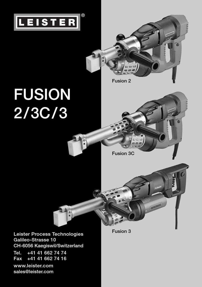
Leister FUSION 1 User manual

Leister Technologies AG
Galileo-Strasse 10
CH-6056 Kaegiswil/Switzerland
Tel. +41 41 662 74 74
Fax +41 41 662 74 16
www.leister.com
FUSION 1
EN

EN
English Operating Instructions 4

3
EN
English Operating instructions
Contents
1.
Important safety instructions ...................................................................................................................4
1.1 Intended use ....................................................................................................................................5
1.2 Non-intended use .............................................................................................................................5
1.3 Safety Instructions ............................................................................................................................5
2.
Technical data ..........................................................................................................................................5
3.
Transport .................................................................................................................................................6
4.
Your FUSION 1..........................................................................................................................................6
4.1 Type plate and identification .............................................................................................................6
4.2 Scope of delivery (standard equipment in the case)............................................................................6
4.3 Overview of device parts ..................................................................................................................7
5.Preparation for welding...........................................................................................................................8
5.1 Welding rod.....................................................................................................................................8
5.2 Switching on....................................................................................................................................8
5.3 Starting the welding process.............................................................................................................9
5.4 Switching off ...................................................................................................................................9
5.5 Checking the temperature of the extrudate and the prewarming air...................................................10
5.6 Replacing the welding shoe.............................................................................................................10
5.7 Welding direction............................................................................................................................10
6.
LCD display.............................................................................................................................................11
6.1 Status display symbols....................................................................................................................11
6.2 Working display ..............................................................................................................................11
7.
Setup menu ............................................................................................................................................13
7.1 Fixing the setpoint temperature setting.............................................................................................14
7.2 Switching off the air supply..............................................................................................................14
8.Quick Reference Guide FUSION 1 ...........................................................................................................15
8.1 Switching on/Starting......................................................................................................................15
8.2 Switching off ..................................................................................................................................15
9.
Warnings and error messages................................................................................................................15
9.1 LCD display for warnings and error messages...................................................................................15
9.2 LED light displays for warnings and error messages..........................................................................16
10.
LED light displays for warnings and error messages...........................................................................17
11.
Accessories ..........................................................................................................................................17
12.
Maintenance.........................................................................................................................................17
13.
Service and repair ................................................................................................................................17
14.
Training.................................................................................................................................................18
15.
Warranty ...............................................................................................................................................18
16.
Other applicable documents.................................................................................................................18
17.
Conformity............................................................................................................................................18
18.
Disposal................................................................................................................................................18

4
Operating instructions (translation of original operating instructions)
EN
LEISTER FUSION 1
manual extrusion welder
Read through the operating instructions before commissioning for the first time.
Always store these operating instructions with the device.
Do not pass the device on to anyone else without the operating instructions.
In addition to the safety instructions contained in the individual chapters of these operating instructions, the
following provisions must also be followed.
1. Important safety instructions
Congratulations on your purchase of the FUSION 1.
You have chosen a first-class hot-air extrusion welder.
It has been developed and produced in accordance with the very latest standards of technology in the plas-
tics-processing industry. It has also been manufactured using high-quality materials.
Warning
FI
Caution
Danger to life
Disconnect the power plug from the socket before opening the device, as
live components and connections will be exposed.
Danger of fire and explosion
If the device is used improperly, there will be a danger of fire and explosion (e.g., due
to the material overheating), particularly in the vicinity of flammable materials and
explosive gases.
Risk of burning
Do not touch exposed metal parts or escaping material while they are hot. The
device should always be allowed to cool down first. Do not point the hot air flow
or escaping material at people or animals.
If the device is being used on construction sites, an FI protective switch must be
used to protect site personnel.
The nominal voltage specified on the device must match the local line voltage.
If the line voltage fails, then the main switch and the drive must be switched o
(extend hot-air blower).
Protect the device from moisture and wet conditions.
The device may only be used under supervision. Waste heat can come into
contact with flammable materials that are not in view.
The device may only be operated by trained specialists or under their supervi-
sion. Children are not permitted to operate the device under any circumstances.

5
The FUSION 1 is designed for professional welding of thermoplastic materials made from PE and PP in the fields
of
• container construction
• pipeline construction
• apparatus construction
• landfill and contaminated sites
• repairs
Use only original Leister spare parts and accessories; otherwise, any warranty or guarantee claims will be invali-
dated.
Welding processes and types of materials
• Welding thermoplastic materials (PE, PP)
Any other use or any use beyond the type of use described is deemed non-intended use.
Subject to change without prior notice.
1.1 Intended use
1.2 Non-intended use
FUSION 1
120 V
FUSION 1
220 V
FUSION 1
220 V / 220 – 240 V
Welding rod
(in acc. with DVS 2211)
Ø mm Ø 3 / Ø 4 ± 0.3 Ø 3 / Ø 4 ± 0.3
Ø 3; output
(mean values at 50 Hz)
kg/ h PE 0.260 – 0.480
PP 0.330 – 0.540
PE 0.260 – 0.450
PP 0.330 – 0.500
Ø 4; output
(mean values at 50 Hz)
kg/ h PE 0.330 – 0.800
PP 0.350 – 0.830
PE 0.330 – 0.750
PP 0.350 – 0.760
The safety instructions for the device can be found in the section on “Safety Instructions – Automatic Welders/
Extrusion Welders/Welding Machines” in the document provided.
You can also find this document in the operating instructions on our website.
1.3 Safety Instructions
2. Technical data
FUSION 1
120 V
FUSION 1
220 V
FUSION 1
220 – 240 V
Nominal voltage V~ 120 220 230
Nominal output W 1450 1100 1200
Frequency Hz 50 / 60 60 50 / 60
Air temperature °C Approx. 180 – 320
Air volume (20 °C) % Approx. 230
Plasticizing temperature °C max. 280
Emission level LpA (dB) < 70 dB (K = 3 dB)
Vibration level ah(m/s2)< 2.5 (K = 1.5 m/s2)
Dimensions (L × W × H) mm 436 × 92 × 236
Weight kg 3.4
Conformity marking /
Protection class II

6
Use only the transport box included in the scope of delivery for transporting the FUSION 1.
The hot-air protective pipe (9) must be allowed to cool down prior to trans-
port.
Never store flammable materials (such as plastic, wood, or paper) in the
transport box.
3. Transport
4. Your FUSION 1
4.1 Type plate and identification
4.2 Scope of delivery (standard equipment in the case)
Example:
The model designation and serial number are indicated on the type plate (5) of your FUSION 1.
Please enter this information in your operating instructions and always reference it when addressing inquiries
to our representatives or authorized Leister Service Centers.
Model:..............................................................................................................................................................
Serial no.:.........................................................................................................................................................
1 x FUSION 1
1 x motor/blower filter set
1 x CL 14 welding shoe
1 x hexagon wrench key, size 3
1 x hexagon wrench key, size 5
1 x original operating instructions
1 x translation of original operating instructions

7
4.3 Overview of device parts
1. Drive motor/blower air inlet
2. Welding rod openings
3. Output regulation potentiometer
4. Handle (can be mounted)
5. Type plate with model designation and series
marking
6. Power cord
7. Hanging hook (optional)
8. Welding shoe
9. Hot-air protective pipe
10. Air temperature potentiometer
11. LCD display
12. Hot-air blower switch
13. Thread for mounting handle
14. LED light, status display
15. On/o drive switch
16. Locking screw (for mounting handle)
1
1098 11
12
5
131415
2
3
6
4
16
4
7
2

8
• Mount the handle (4) on the FUSION 1 (using locking nut 13) if required. Observe the maximum tightening
torque of 4 Nm.
• Prior to commissioning, check the power cord (6), the plug, and the extension cable for electrical and me-
chanical damage.
• The minimum cross-section must be observed if an extension cable is being used:
Length
[m]
Minimum cross-section (at ~230 V)
[mm2]
Up to 19 2.5
20 – 50 4.0
• Extension cables must be authorized for the utilization site (e.g., outdoors) and marked accordingly.
• When a power generator is used as an energy supply, the following applies for its nominal output: 2 x hand
extruder nominal output.
The FUSION 1 must not be used in areas with explosion and/or ignition
hazards. Ensure that you are in a stable position while working. The connection cable and
welding rod must be able to move freely and must not hinder the user or third parties while
working.
5. Preparation for welding
5.1 Welding rod
5.2 Switching on
Use only a PE/PP welding rod with Ø 3 or Ø 4 mm for the FUSION 1.
• Connect the FUSION 1 to the electrical line supply.
• Switch on the FUSION 1 using the hot-air blower switch (12).
• Use the air temperature (10) potentiometer to adjust the hot-air temperature. The set value appears on the
LCD display (11).
• After around 5 minutes, the operating temperature is reached and the LED (14) lights up.
Starting protection
The FUSION 1 is equipped with drive overload protection. If the speed becomes too low, the drive
switches o automatically. For example, the drive cannot be started or can only be started for a short time if
the material is insuciently plasticized in the screw. Reheating then takes place for another 2 minutes.
A countdown counter appears on the status display area of the LCD display (11).

9
5.4 Switching off
• Press the on/o drive switch (15).
• Remove the welding material from the welding shoe so the welding shoe is not damaged the next time the
device is started.
• The FUSION 1 may now be stored on its side.
• Set the air temperature potentiometer (10) to “0”. Allow the device to cool down.
• Switch o the hot-air blower switch (12).
The hot air flow must not be pointed at
people, animals, or objects
Use a fireproof support
Overheating protection
If the drive is overheated due to external influences or if the melting temperature of the material in the screw is
too low,
the internal temperature protection will switch the drive o. Er 0400 will appear on the display (11). Disconnect
the FUSION 1 from the line supply and allow it to cool down.
5.3 Starting the welding process
If necessary, mount the appropriate welding shoe (8) (see Chapter 5.6, “Replacing the welding shoe”).
• Once the operating temperature has been reached, welding can start. To do this, press the on/o drive switch
(15). Always operate the FUSION 1 with the welding rod inserted.
• Insert the welding rod (Chapter 5.1, “Welding rod”) into one of the welding rod openings (2) and allow some
material to escape.
CAUTION: Never insert the welding rod into both welding rod openings at the same time.
• The welding rod must be clean and dry when it is inserted.
• The output can be changed on the basis of the rod geometry and choice of material using the output regula-
tion potentiometer (3). The set speed appears in a bar graph on the display (11).
• Pause the delivery of material using the on/o drive switch (15).
• Point the prewarming nozzle (17) at the area to be welded.
• Prewarm the area to be welded with oscillating movements.
• Place the FUSION 1 on the prepared area to be welded and press the on/o drive switch (15).
• Create and analyze a sample weld.
• Adjust the hot-air temperature as necessary using the air temperature potentiometer (10) and the output
volume as necessary using the output regulation potentiometer (3).
• The welding rod is automatically drawn through the welding rod opening (2) after starting.
It must be possible to insert the rod without resistance.
17

10
5.5 Checking the temperature of the extrudate and the prewarming air
• The temperature of the extrudate and the hot air flow must be checked regularly during extended periods of
welding work:
Fast-indicating electronic temperature probes with suitable temperature sensors must be used for this purpose.
You must identify the highest temperature in the hot air flow between the nozzle outlet level and a depth of 5
mm. During extrudate measurement, the measurement sensor in the welding shoe must be inserted into the
middle of the strand.
8 Welding shoe
18 Clamping screws
19 Prewarming nozzle
20 Welding shoe holder
21 Fastening screws
22 Extruder nozzle
Risk of burning
Always work with temperature-resistant gloves.
5.6 Replacing the welding shoe
• The welding shoe must be replaced while the device is warm.
5.7 Welding direction
• Detaching the clamping screws (18) allows the
welding shoe (8) to be rotated freely to the required
welding direction.
• The clamping screws (18) must then be retightened
well again.
• Removal
– Remove the welding shoe (8) with the welding shoe holder (20) by detaching the clamping screws (18)
from the extruder nozzle (22).
– Every time the welding shoe is replaced, clean the extruder nozzle (22) by removing any welding residue from
it and make sure that it is screwed in tightly. Note: left-hand thread
– Remove the welding shoe (8) by detaching the fastening screws (21) from the welding shoe holder (20).
• Mounting
– Mount a welding shoe (8) that is adapted for the welding rod on the welding shoe holder (20) using fas-
tening screws (21).
– The welding shoe (8) and welding shoe holder (20) must be tightened well using the clamping screws
(18).
Switch o the FUSION 1 while it is warm and disconnect it from the electrical line supply.
8
19
20
21 22
18

11
Countdown counter for heating process. Display of the remaining operating hours after warning of the
blower motor service message.
Cooling process
Setpoint setting locked
Line voltage is present, FUSION 1 is switched o
Startup
As soon as the FUSION 1 is connected to the
line voltage specified on the type plate (5), the
current software version appears on the LCD
display (11) for approximately 2 seconds.
If the hot-air blower switch (12) is at position
“0”, the power plug symbol appears on the status
display area of the LCD display.
Setting the
temperature set-
point
Set the switch for the hot-air blower (12) to
position “1”. The potentiometer (10) can now
be used to set the air temperature. The current
setting is displayed on the LCD display (11).
Heating process
Once the potentiometer (10) is no longer being
pressed, the system switches to the actual value
display. During the heating process, the current
temperature flashes on the display. An arrow
pointing upward indicates that the temperature
is rising.
6. LCD display
The LCD display (11) is subdivided into three display areas:
6.1 Status display symbols
6.2 Working display
Status display
Setpoint/actual welding temperature value
Drive motor bar display

12
Countdown counter
When the temperature is > 180 °C, the count-
down counter starts. The heating process now
lasts another 5 minutes.
Operating readiness
and output regula-
tion adjustment
Once the heating time has elapsed, the LED
light (14) switches on. The drive display now
shows the actual set temperature value and the
bar display with the current output regulation
setting. The potentiometer (3) can now be used
to adjust the output regulation. The FUSION 1 is
ready for extrusion.
Note:
It is not possible to adjust the temperature during
extrusion. If a setting is made on the potentiom-
eter (10) during extrusion, the set value is not
applied until the drive motor is stopped by the
switch (15) being pressed.
Caution:
Check the temperature setting
after the drive stops
Cooling process
The air temperature potentiometer (10) must
be rotated counterclockwise as far as it will go,
to the “0” position, in order to allow the FUSION
1 to cool down. The LED light (14) switches o.
The status display area of the LCD display (11)
shows a snowflake, a flashing arrow pointing
downward, and the actual temperature value. As
soon as the temperature is below 50 °C, “OFF”
appears on the LCD display. The FUSION 1 can
now be disconnected from the line supply.

13
7. Setup menu
°C/°F switching
Temperature setting
locking
Save settings
Software release
Drive button on
> 2 s
Drive button on
> 2 s
Drive button o
Drive button o
Drive button on
> 1 s
Drive button on
< 1 s
Hot-air blower
switch on
Hot-air blower
switch o
Drive button on
> 2 s
Drive button on
< 1 s

14
Setting the required
setpoint
Use the air temperature potentiometer (10) to
set the required temperature.
Activating
fixing
Disconnect the FUSION 1 from the line supply
and activate the Setup menu (see Chapter 7,
“Setup menu”).
Use the “bo” menu item to activate setpoint fixing
(“On”).
A padlock appears on the status display.
The setpoint that was previously set is perma-
nently saved and can no longer be changed. You
can cool down the FUSION 1 by rotating the air
temperature potentiometer (10) counterclock-
wise as far as it will go, to the “0” position. As
soon as the potentiometer is turned clockwise
again, the setpoint that was previously saved is
applied.
Deactivating
fixing
Disconnect the FUSION 1 from the line supply
and activate the Setup menu (see Chapter 7,
“Setup menu”).
Use the “bo” menu item to deactivate setpoint
fixing (“OFF”; see Chapter 7, “Setup menu”).
The temperature setpoint can now be set again
as required.
Switching o the air
supply
Use the hot-air blower switch (12) to switch o
the heating and the blower. A countdown counter
appears on the status display area of the LCD
display (11). You can extrude without the air
supply for a maximum of 60 seconds. If you do
not switch the hot-air blower back on during this
time, the extruder drive will stop.
7.1 Fixing the setpoint temperature setting
The FUSION 1 provides the option of fixing the setpoint temperature setting. This prevents the required tempera-
ture from being changed. This function is deactivated in the device’s as-delivered state.
7.2 Switching off the air supply
In certain situations, it is necessary to switch o the air supply temporarily.
The FUSION 1 provides this option.

15
Message type LCD display Description and measures
Error Thermocouple faulty *
* Contact Leister Service Center
Error
Overheating protection has responded. Allow the FUSION 1 to
cool down and try again. Check whether the blower is running
correctly. If the error keeps occurring, contact the Service
Center.
Error
The carbon brushes of the blower are used up and must
be replaced at your service center. To protect the heating
element, the heater is no longer activated.
8. Quick Reference Guide FUSION 1
9. Warnings and error messages
8.1 Switching on/Starting
1. Make sure that the main switch (12) is switched o.
2. Connect the line voltage plug (6).
3. Switch on the main switch (12).
4. Set the welding temperature using the potentiometer (10).
5. The heating switches on and the display (11) flashes.
6. Wait around 5 minutes until the required temperature is reached.
7. The LED (14) lights up and the rod feed speed can now be set using the
potentiometer (3).
8. Press the on/o drive switch (15); the extruder starts running.
8.2 Switching off
1. Press the on/o drive switch (15); the drive motor stops.
2. Using the potentiometer (10), rotate the heating setting all the way back
to 0 to activate cool-down mode. The LED (14) switches o.
3. Wait until the end of the cool-down process (around 6 minutes).
4. Switch o the main switch (12).
5. Disconnect the line voltage plug (6).
Warnings and error messages are shown either by means of the integrated LED light (14) or on the LCD display
(11).
It is not possible to continue working once an error message has appeared. The heating is switched o
automatically and the drive is blocked. After a drive motor overload, you must reset the electronics in order to
continue working. To do this, you must disconnect the FUSION 1 from the power by pulling out the power plug.
9.1 LCD display for warnings and error messages

16
Error
Drive overload, switch o FUSION 1, disconnect power plug,
and allow FUSION 1 to cool down. Try again with a higher
prewarming temperature. If the error keeps occurring, contact
the Service Center.
Warning The drive for output regulation is not reaching the setpoint
speed. Heating-up phase is extended by 2 minutes.
Warning
Service message: The drive motor for output regulation has
been working for over 300 operating hours. Press the drive
(15) switch to reject this message and stop the work that is
due to take place. The drive carbon brushes should initially be
replaced by your Service Center.
Warning
Service message: The blower motor has been working for
over 1,000 operating hours. Press the drive (15) switch to re-
ject this message and stop the work that is due to take place.
The blower carbon brushes should initially be replaced by your
Service Center. The carbon brushes of the blower must be
replaced at your service point within 50 operating hours.
Warning
The operating hours counter for the blower has exceeded the
permissible run time. You can still work with the device for
a maximum of 50 hours. The remaining operating hours are
continuously displayed.
Message type LED light Description and measures
Status display O Cool down, heating switched o, FUSION 1 not ready for
operation
Status display On Device is ready for operation
Error 2 x per second
Blower error
Carbon brushes worn down *
Heater is blocked
* Contact Leister Service Center
Drive error:
Drive overload, switch o FUSION 1, disconnect power
plug, allow to cool down, and try again with a higher
prewarming temperature
Voltage supply error
Line voltage > 20% -> heating overtemperature
Line frequency < 15 Hz or > 100 Hz
9.2 LED light displays for warnings and error messages

17
Extruder not heating:
• Heating knob at position “0”
• Heating element faulty *
• Blower carbon brushes used up
Deficient welding result quality:
• Check the welding speed and welding temperature.
• Clean the welding shoe (8).
After 7 minutes at the most, the set welding temperature (extended heating process)
has still not been reached:
• Check the line voltage.
* Contact Leister Service Center
Use only original Leister spare parts and accessories; otherwise, any warranty or guarantee claims will be invali-
dated.
You can find more information at www.leister.com.
• Clean the air inlet (1) with a brush if it is dirty. Remove the filter to do this: Gently press in the clips at the side
and pull them up and o.
Have your Leister Service Center check the carbon brushes of the drive after around 300 operating hours. The
drive will switch o automatically once the minimum carbon length has been reached. The carbon brushes of the
blower are used up after approx. 550 operating hours and must then be replaced at your Leister Service Center.
To protect the heating element, the heater is no longer activated if the carbon minimum length is undercut.
Operating times: Drive approx. 300 hours (carbon brushes)
Heating air blower approx. 550 hours (carbon brushes)
• Every time the welding shoe is replaced, clean the extruder nozzle (22) and remove any welding residue from
it (Chapter 5.6, “Replacing the welding shoe”).
• Check the power cord and plug for interruptions and mechanical damage.
10. LED light displays for warnings and error messages
11. Accessories
12. Maintenance
13. Service and repair
21
1

18
Repairs must only be carried out by authorized Leister Service Centers.
Leister Service Centers guarantee a professional and reliable repair service within 24 hours with original spare
parts in accordance with circuit diagrams and spare parts lists. You will find the address of your authorized Service
Center on the last page of these operating instructions.
You can find more information at www.leister.com.
Leister Technologies AG and its authorized Service Centers oer welding courses and introductory training class-
es. You can find more information at www.leister.com.
• The guarantee or warranty rights granted for this device by the direct distribution partner/salesperson apply
from the date of purchase.
• In the event of a guarantee or warranty claim (verification by invoice or delivery note), manufacturing or pro-
cessing errors will be rectified by the sales partner through replacement delivery or repair.
• Other guarantee or warranty claims are excluded within the framework of mandatory law.
• Damage resulting from natural wear, overload, or improper handling is excluded from the warranty.
• Heating elements are excluded from warranty obligations or guarantees.
• Guarantee or warranty claims cannot be asserted for devices that have been converted or changed by the
purchaser or for which non-original Leister spare parts have been used.
14. Training
15. Warranty
EU Declaration of Conformity
Leister Technologies AG, Galileo-Strasse 10, 6056 Kaegiswil, Switzerland confirms that in the model made avail-
able for purchase, this product fulfills the requirements of the following EU directives.
Directives: 2006/42/EG, 2011/65/EU, 2014/30/EU
Harmonized standards: EN ISO 12100, EN 55014-1, EN 55014-2, EN 61000-6-2, EN 61000-3-2,
EN 61000-3-3, EN 62233, EN 60335-1, EN 60335-2-45, EN IEC 63000
Kaegiswil, 1/5/2021
Bruno von Wyl, CTO Christoph Baumgartner, GM
UK Declaration of Conformity
Leister Technologies AG, Galileo-Strasse 10, 6056 Kaegiswil, Switzerland confirms that these products, in the
versions as brought into circulation through us, fulfil the requirements of the following UK Statutory Instruments.
UK Statutory
Instruments: 2008 No. 1597, 2016 No. 1091, 2012 No. 3032
Designated EN ISO 12100, EN 55014-1, EN 55014-2, EN 61000-6-2, EN 61000-3-2,
Standards: EN 61000-3-3, EN 62233, EN 60335-1, EN 60335-2-45, EN IEC 63000
Kaegiswil, 3/31/2021
Bruno von Wyl, CTO Christoph Baumgartner, GM
Do not dispose of electrical equipment with household refuse.
Electrical appliances, accessories and packaging should be recycled in an environmentally friendly
manner. When you are disposing of our products, please observe the national and local regulations.
Safety Instructions – Automatic Welders/Extrusion Welders/Welding Machines (Article number: 129.102)
16. Other applicable documents
17. Conformity
18. Disposal


Your authorised Service Centre is:
Leister Technologies AG
Galileo-Strasse 10
CH-6056 Kaegiswil/Switzerland
Tel. +41 41 662 74 74
Fax +41 41 662 74 16
www.leister.com
© Copyright by Leister
FUSION 1 / 12.2021
Art. 162.816
Other manuals for FUSION 1
1
Table of contents
Other Leister Welding Accessories manuals