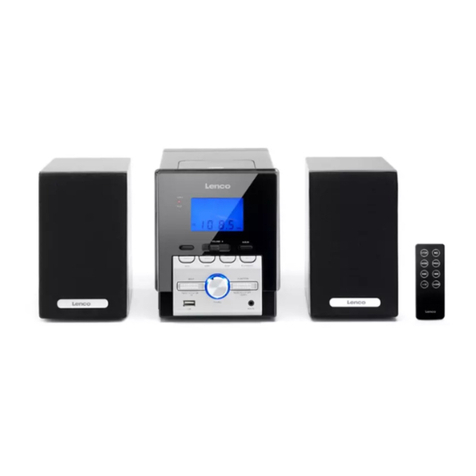
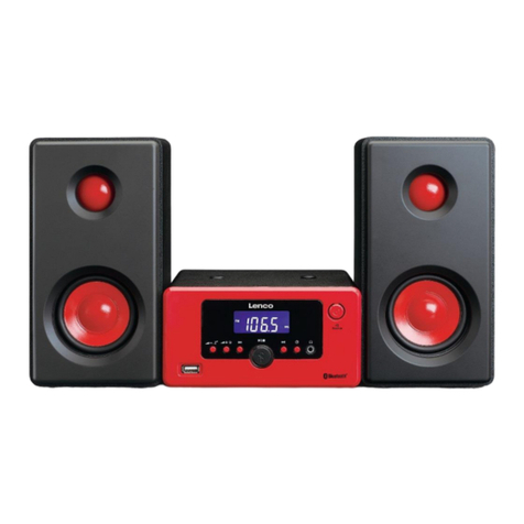
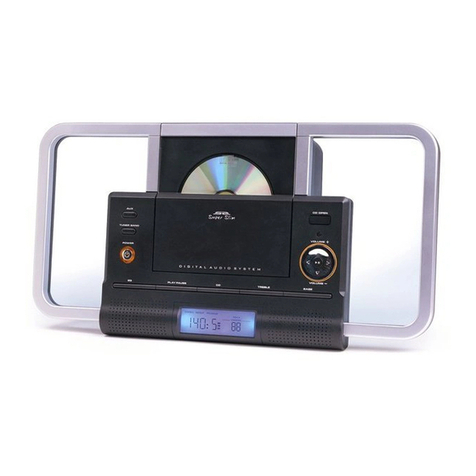
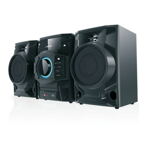
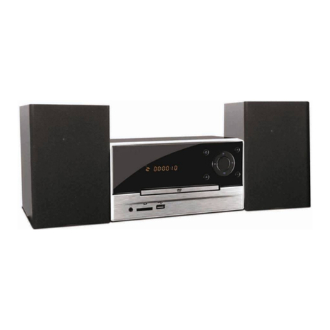
LENCO NXT-01 User manual

NXT-01
OWNER'S MANUAL

- 1 -
C A U T I O N
TO PREVENT FIRE OR SHOCK HAZARD, DO NOT USE THIS PLUG WITH AN
EXTENSION CORD, RECEPTACLE OR OTHER OUTLET UNLESS THE BLADES
CAN BE FULLY INSERTED TO PREVENT BLADE EXPOSURE. TO PREVENT FIRE
OR SHOCK HAZARD, DO NOT EXPOSE THIS APPLIANCE TO RAIN OR MOISTURE.
IMPORTANT SAFETY INSTRUCTIONS
1.) Read these instruction
s.
2.) Keep these instructions.
3.) Heed all warnings.
4.) Follow all instructions.
5.) Do not use this apparatus near water.
6.) Clean only with dry cloth.
7.) Do not block any ventilation openings. Install in accordance with the manufacturers
instructio
ns.
8.) Do not install near any heat sources such as radiators, heat registers, stoves, or other
apparatus (including amplifiers) that produce heat.
9.) Do not defeat the safety purpose of the plug. If the provided plug does not fit into your outlet,
consu
lt an electrician for replacement of the obsolete outlet.
10.) Protect the power cord from being walked on or pinched particularly at plugs, convenience
receptacles, and the point where they exit from the apparatus.
11.) Only use attachments / accessories
specified by the manufacturer.
12.) Unplug this apparatus during lightning storms or when unused for long periods of time.
13.) Refer all servicing to qualified service personnel. Servicing is required when the apparatus
has been damaged in any way, such as power-supply cord or plug is damaged, liquid has been
spilled or objects have fallen into the apparatus, the apparatus has been exposed to rain or
moisture, does not operate normally, or has been dropped.
14.) This appliance shall not be exposed to dripping or splashing water and no object filled with
liquids such as vases shall be placed on the apparatus.
15.) Do not overload wall outlet. Use only power source as indicated.
16.) Use replacement parts as specified by the manufacturer.
17.) The product may be mounted to a wall only if recommended by the manufacturer.
18.) Upon completion of any service or repairs to this product, ask the service technician to
perform safety checks.
The lightning flash with arrowhead
symbol, within an equilateral
triangle is intended to
alert the user
to the presence of insulated
dangerous voltage
within the
product s enclosure that may be of
sufficient
magnitude to constitute a
risk
of electric shock to persons.
WARNING: TO REDUCE THE
RISK OF ELECTRIC SHOCK
DO NOT REMOVE COVER
(OR BACK) , NO USER
SERVICEABLE PARTS INSIDE
REFER SERVICING TO
QUALIFIED
SERVICE
PERSONNEL.
The exclamation point within
an equilateral triangle is
intended
to alert the user to
the presence of important
operating and maintenance
(servicing) instructions in
the
literature accompanying
the appliance.

- 2 -
IMPORTANT NOTES
Avoid installing this unit in places
exposed to direct sunlight or close
to
heat radiating appliances such
as
electric heaters, on top of other stereo
equipment that radiates too much heat,
places lacking ventilation or dusty
areas, places subject to constant
vibration and/or humid or moist areas.
No naked flame sources, such as
lighted candles, should be placed on
the apparatus.
The apparatus shall not expose to
dripping or splashing. No objects filled
with liquids, such as vases, shall be
placed on the apparatus.
Do not attempt to clean this unit with
chemi
cal solvents as this might
damage the finish. Use a clean dry
cloth.
Operate controls and switches as
described in the manual.
Before turning On the power, make
certain that power cord is properly
installed.
Store your CDs, in a cool area to avoid
dam
age from heat.
When moving the set, be sure to first
disconnect the power cord.
CLASS 1 LASER PRODUCT
APPAREIL Á LASER DE CLASSE 1
PRODUCTO LASER DE CLASE 1
CAUTION
INVISIBLE LASER RADIATION
WHEN OPEN AND INTERLOCKS
DEFEATED.

- 3 -
PREPARATION FOR USE
UNPACKING AND SET UP
This system consists of the following components: Tuner/CD Player unit
,
Remote Control, AM Antenna and FM Antenna. Carefully remove all the
components from the display carton and verify that you have all the
necessary components before you dispose of the display carton.
Remove all packing materials from the individual components. Remove any
descriptive labels that may be attached to the front panel of the main unit. Do
not remove any labels or stickers on the back panels of the main unit or the
speakers.
Remove any small strips of tape that may have been used to prevent the CD
door from opening in transit.
Place all the components in the desired location. This system is designed to
be used on level, stable, flat surface such as a table, desk, shelf, or stand,
convenient to an AC outlet, out of direct sunlight, and away from sources of
excess heat, dust, moisture, or vibration.
Unwind the AC power cord on the back of the Amplifier/Subwoofer unit and
exte
nd the cord to its full length.
Plug the
AM/
FM antenna
to
the
top
of the Tuner/CD Player unit and extend it
to its full length.
The main unit is shipped with a dummy CD display card in the CD player.
This dummy CD card must be removed before you can
use the CD player.

- 4 -
POWER SOURCE
This system is designed to operate on
220V
AC
50Hz house current only.
Connecting this system to any other power
source may cause damage to the system and
such damage
is
not covered by your warranty.
NOTE:
The system has
an
AC plug and will only fit into matching AC outlets. This
is a safety
feature to reduce the possibility of
e
lectric
shock. If the plug will not fit in
your AC
outlets,
you should have
the
outlet changed by a qualified, licensed
electricia
n. Do not use an adapter to make the plug fit into your outlet. This
defeats the safety feature and could expose you to electric shock.
MAIN POWER SWITCH
IMPORTANT:
The
MAIN
power
SWITCH
is located on the
side
of the
main
unit.
This switch must be
ON
for the system to operate. The main
power switch should
be left in the
ON
position at all times. The only time you should set this switch
back to the
OFF
position is if you will not be using the system for an extended
period of time
for example, two weeks or longer. The remote controller cannot
operate the system if main power switch is in the
OFF
position.

- 5 -
AUXILIARY SOURCE CONNECTIONS
You can listen to the sound from external audio sources through the speakers of
this system. Connect the Aux/Line/Audio Output Jacks of the external audio
source
to the
AUX IN
Jack at the back panel of
Tuner/CD
unit.
Note: Connection cables are not included.
Examples of External Audio Sources that can be connected to this system are:
Cas
sette Player, Mini Disc Player, the sound from your TV, VCR, DVD player, etc.
Instructions for listening to external audio sources will be found later in this
manual.
PROTECT YOUR FURNITURE
This model is equipped with non-skid rubber 'feet' to prevent the product from
moving when you operate the controls. These 'feet' are made from non-
migrating
rubber material specially formulated to avoid leaving any marks or stains on your
furniture. However certain types of oil based furniture polishes, wood
preservat
ives,
or cleaning sprays may cause the rubber 'feet' to soften, and leave
marks or a rubber residue on the furniture. To prevent any damage to your
furniture we strongly
recommend that you purchase small self
-
adhesive felt pads,
available at hardware
store
s and home improvement centers everywhere, and
apply these pads to the
bottom of the rubber 'feet' before you place the product on
fine wooden furniture.

- 6 -
REMOTE CONTROL BATTERY
The remote control requires o
ne button-type 3-
volt lithium
battery, included. To extend the life of the original battery we
have inserted a small clear plastic spacer tab between the
lithium battery and the battery terminal. You must remove this
battery spacer tab before you can use the remote control. To
remove the
tab, pull it in the direction of the arrow in the
illustration as shown.
When the operation of the remote control becomes intermittent or unsatisfactory,
replace the original battery with a new 3
-
volt lithium battery.
1.)
Slide out the battery holder fro
m the remote control case.
2.)
Place one 3V
CR2032
battery in the battery holder, observing the positive (+)
direction. If the battery is placed incorrectly the remote control will not work.
CAUTION
Danger of explosion if battery is incorrectly repl
aced.
Replace only with the same or equivalent type.
3.)
Insert the battery holder into the battery slot.
Notes:
Use a well-known brand of cell battery for longest life and best
performance. When the remote operation becomes intermittent, replace the
battery
.

- 7 -
LOCATION OF CONTROLS AND INDICATORS
MAIN
UNIT
FRONT
VIEW
BACK
VIEW

- 8 -
TOP
VIEW
SIDES
VIEW

- 9 -
1.)
FUNCTION
Button
2.)
STANDBY/ON
Button
3.)
SD/MMC
Card
Slot
4.)
USB
Jack
5.)
CD Door
OPEN / CLOSE
Button
6.)
Remote Control Sensor
7.)
DIGITAL
VOLUME +
Button
8.)
SKIP / TUNE
Button
9.)
SKIP / TUNE
Button
10.)
DIGITAL
VOLUME
Button
11.)
CLOCK / PROG
RAM
Button
12.)
TIMER
Button
13.)
SLEEP
Button
14.)
STEREO / MONO /
FIND
Button
15.)
PRESET
/ ALBUM
Button
16.)
LCD Display with Backlight
17.)
PRESET
/ ALBUM
+
Button
18.)
REPEAT
/
RDS PTY
Button
19.)
RANDOM
/
RDS MODE
Button
20.)
STOP
/
BAND
Button
21.)
FM ANTENNA
22.)
AM ANTENNA
23.)
Metal Heat Sink
24.)
Battery Compartment
25.)
MAIN POWER
Switch
26.)
AC Power Input
27.)
AUX IN
Jack
28.)
EARPHONE
Jack

-
10
-
REMOTE CON
TROL
1.
STANDBY / ON
Button
2.
OPEN/CLOSE
Button
3.
PLAY / PAUSE
Button
4.
STOP / BAND
Button
5.
VOLUME +
Button
6.
SKIP / TUNE
Button
7.
VOLUME
Button
8.
PRESET
/ ALBUM
+
Button
9.
T
IMER
Button
10.
SLEEP
Button
11.
PRESET
/ ALBUM
Button
12.
RANDOM
/
RDS MODE
Button
13.
RE
PEAT
/
RDS PTY
Button
14.
FUNCTION
Button
15.
CLOCK/
PROGRAM
Button
16.
SKIP / TUNE
Button
17.
TREBLE
+
Button
18.
BASS +
Button
19.
BASS
-
Button
20.
TREBLE
-
Button
21.
MUTE
Button
22.
STEREO / MONO /
FIND
Button
23.
Battery Compartment (Back
Cabinet)

-
11
-
OPERATING INSTRUCTIONS
Make sure that the MAIN Power SWITCH on the back of the
Amplifier/Subwoofer unit is ON .
Make sure that you have removed the battery spacer from the remote
control handset.
Make sure the AC power cord from the Amplifier/Subwoofer unit is
properly connected to a
220V
5
0H
z household AC power outlet.
Make sure that the
minimum
distance
around
the whole unit for
sufficient ventilation is 10cm.
USING THE CONTROLS
Most of the functions of this system can be operated by pressing the buttons on
the
top
panel, or the corresponding buttons on the remote control handset. If a
particular function can only be operated by controls on the remote control, the
instructions will specify:
Remote Control Only

-
12
-
SETTING THE CLOCK
When the system is connected to the AC outlet for the first time and
--
:
--
will
keep flashing on the display. This is your indication that the time display is
incorrect and needs to be reset.
Set the Clock time in the Standby mode.
1.)
While the unit is in the Standby mode, press and
hold
the
CL
OC
K/
PROG
button on the remote
control for 3 seconds to enter Clock Set mode.
24
HOUR shows with
24
keep flashing in the display
indicating that the clock is set for
24
-hour
European
time.
2.)
Press
the
SKIP/TUNE
or
buttons on the top
panel or on the remote control once to change the
clock format to
12
Hour
American
time. The
display will change from
24
HOUR to
12
HOUR .
3.)
Press the
CLOCK/PROG
button again to confirm.
The Hour digits will begin flashing.
4.)
P
ress
the
SKIP/TUNE
or
buttons on the top
panel or on the remote control to set the display to
the correct Hour,
AM
or PM.
Note
: If you choose 12 hour format, the first 12 hour is for AM, and the next 12
hour is for
P
M.
5.)
Press the
CLOCK/PROG
button again the top panel or on the remo
te control,
the Minutes digits begin flashing.
6.)
P
ress
SKIP/TUNE
or
buttons on the
top panel
or on the remote control to set the display to the
correct Minute.
7.)
Press the
CLOCK/PROG
button once more. The time display stops flashing
and the clock begin t
o run.
Note:
The correct time will appear on the display when the system is in the
Standby
Mode.

-
13
-
MAIN VOLUME
,
VARIABLE BASS
AND TREBLE
CONTROLS
VOLUME ADJUSTMENT
Press the
VOL
+
or VOL
buttons on the
top
panel or
on the remote control to increase or decrease the
volume. The volume level indicator appears on the
main display.
The range is from 00 (Minimum) to
30
(Maximum).
This system will remember the last volume level you selected before switching the
power Off and will automatically return to that volume level when the power is
switched On again. (Unless the volume is large then 25, then the volume will
automatically switch back to 25 as the last volume.)
Note
: If the
MAIN
Power
SWITCH
on the back panel of the subwoofer is switched
'
OFF
', or if the AC power is interrupted, the volume level will return to the
13
default level when the power is restored.
VARIABLE BASS CONTROL
(Remote Control Only)
Press the
BASS
+
or
on the remote control to
increase or decrease the amount of bass response
from the subwoofer speaker.
Notes:
Variable Bass
C
ontrol
set
to 0 as the default level. The range is from -6
(Minimum) to +6 (Maximum).
VARIABLE TREBLE CONTROL (Remote Control Only)
Press the TREBLE + or
on the remote control to
increase or decrease the amount of treble response
from the 2 satellite speakers.
Note: Variable Treble Control set to
0 as the default level.
The range is from
-6
(Minimum) to
+6
(Maximum).
MUTE Button (Remote Control Only)
To temporarily shut off the sound fr
om the speakers
by
press
ing
the
MUTE
button on the remote control. The
MUTE
message
will begin flashing and the
sound will
stop. Press the
MUTE
button again to cancel Mute and
restore the sound. The
MUTE
indicator
will
disappear
from the display.

-
14
-
ANTEN
NA INFORMATION
FM
Make sure the FM lead wire antenna is
plugged
into the FM antenna jack on the
top of the main unit and the wire is
unwound
ed
and extended to its full length. It
may be necessary to vary the direction of this wire antenna until you find t
he
position
that provides the best reception for your favorite FM stations.
AM
The
AM
ferrite bar antenna is inside the main unit. If
AM
reception is
unsatisfactory,
you may have to turn the main unit slightly until you find the
position tha
t provides
the best reception.

-
15
-
LISTENING TO THE RADIO
1.)
Press the
STANDBY
/ON
button on the
top
panel or on the remote control. The
main display turns on.
Pr
ess the
FUNCTION
button repeatedly on the
top
panel or on the remote control to switch between
various modes.
Note:
The looping order of the
FUNCTION
button is:
TUNER
CD
AUX
CARD
-
USB
.
The display will show an
MW
or
FM
station frequency.
To select a different band (
MW
or FM), press the
STOP/BAND
button on the top panel or on the
remote control.
Note
: In FM station with Stereo support, you can
press
ST/MO/
FIND
button to select between
Stereo or Mono sound. If the reception is noisy or
weak, press the button
ST/MO/
FIND
to the mono
setting. The STEREO indicator will disappear. The reception will normally
improve although the sound will no longer be in stereo.
2.)
Tune to the desired frequency as follows:
Manual Tuning
Repeatedly press
the
SKIP/TUNE
or
buttons
on the top panel or on the
remote control until the frequency of the desired station appears on the
display.
Automatic Tuning
Press and hold the
SKIP/TUNE
or
buttons on the top panel or on
the
remote control until the display begins to move,
and then release the buttons.
The tuner will search up or down the frequency fo
r the next strong station and
stop on that station. Repeat this procedure until the tuner stops on your
desired station.

-
16
-
PRE
-
SETTING STATIONS IN THE TUNER MEMORY
This system includes a
40
station preset memory. You can store up to
30
FM
stations and
10
AM
stations in the tuner memory for immediate recall. The
procedure for storing stations in memory is as follows:
1.)
Follow step 2 under LISTENING TO THE RADIO to select the first station
you wish to memorize.
For e
xample: FM 103.5 MHz.
2.)
When the desired station appears on the display,
press the
CLOCK/
PROG
button
on the top panel or
on the remote control. The
PROGRAM
indicator
shows and Preset Memory Number 01 flashes in
the display. Press the PRE/ALB +
or
button on
the remote control to selec
t the memory number.
In this case, choose
01
as the memory number.
3.)
Press the
CLOCK/
PROG
button again to save the
memory. The display shows the preset memory
number
01
and the saved frequency FM 103.50
MHz
to indicate the station is stored in
the selected
preset memory.
4.)
Tune to the next station you wish to memorize.
When the desired station appears on the display,
press the
CLOCK/
PROG
button to start the
PROGRAM
indicator showing on the display, and
then press the PRE/ALB +
or
button to select a
different preset memory number.

-
17
-
5.)
Press the
CLOCK/
PROG
button again to enter the station in the selected
preset memory number.
6.)
Repeat steps 4 and 5 until you have memorized up to
30
stations on
FM
band,
then press the
STOP/BAND
button
to switch to the
AM
band and follow the
same procedure to enter up to 10 stations on the
AM
band.
Note
: The saved preset station will be lost if the
MAIN
Power
SWITCH
on the
back panel of the subwoofer is switched '
OFF
', or if the AC power is interrupted.
RECA
LLING PRESET STATIONS
Turn the system On . Press the PRE/ALB +
or
button repeatedly to scroll
through the preset memories until the display shows the desired station.
CHANGING PRESET STATIONS
To change any preset station memory, select the desired ban
d and tune to the
new station you wish to memorize.
Press the
CLOCK/
PROG
button and then press the PRE/ALB +
or
button to
display the memory number you wish to change.
Press the
CLOCK/
PROG
button again to enter the new station in the memory.
The new station is memorized and the previous station is deleted from the
memory.

-
18
-
RDS Mode
RDS Display
Press
RDS MODE button once, PS is displayed. Then
the RDS indicator light up and the station name
appear
.
No PS appears if no RDS signal is sent
.
Press
RDS MODE button twice, PTY is display. Then
the RDS indicator light up and the broadcast program
type appear.
No PTY appears if no RDS signal is sent.
Press
RDS MODE
button three times, RT is displayed.
Then, the RDS indicator light up and a text message
sent by the station appear.
No RT appears if no RDS signal is sent.

-
19
-
RDS Display
Press
RDS PTY
button. PTY SEL is displayed
.
Then
press the
SKIP/TUNE
or
buttons, the display shows a category in the
following
order:
NEWS <
-
> AFFAIRS <
-> INFO <-
> SPORT <
-
> EDUCATE <
-
> DRAMA <
-
>
CULTURE <
-
> SCIENCE <
-
> VARIED <
-
> POP M <
-
> ROCK M <
-
> M O R M <
-
>
LIGHT M <
-
> CLASSICS <
-
> OTHER M <
-
> WEATHER <
-
> FINANCE <
-
>
CHILDREN <
-
> SOCIAL A <
-
> RELIGION <
-
> PHONE IN <
-
> TRAVEL
<
-
>
LEISURE <-
> JAZZ <
-
> COUNTRY <
-
> NATIONAL <
-
> OLDIES <
-
> FOLK M <
-
>
DOCUMENT <
-
> NEWS
Press
RDS PTY
button
to confirm the category.
Press RDS PTY button again
to start searching
. While
searching, SEARCH and the selected PTY code
alternately appea
r on the display.
The Unit search 30 preset stations and stops when it
finds a station of the category you have selected, then
tunes into the station.
If no program if found, NOT and FOUND alternately
appear on the display.
Other manuals for NXT-01
1
Table of contents
Other LENCO Stereo System manuals

LENCO
LENCO SCR-94 User manual

LENCO
LENCO MC-148 DAB+ User manual

LENCO
LENCO PA-1500 User manual

LENCO
LENCO SCD-681 User manual

LENCO
LENCO MC-129 MP3 RDS User manual

LENCO
LENCO MDV-8 User manual

LENCO
LENCO MC-250 User manual

LENCO
LENCO ID-2 User manual

LENCO
LENCO MC-144 User manual

LENCO
LENCO NXT-01 User manual