manuals.online logo
Brands
  1. Home
  2. •
  3. Brands
  4. •
  5. LENCO
  6. •
  7. Turntable
  8. •
  9. LENCO L 75 User manual

LENCO L 75 User manual

Hi-Fi
Record
Player
L75
Operating
instructions
Features
The
Lenco
L.75
Record
player
is
a
precision
instru-
ment
of
true
Hi-Fi
quality
which
will
satisfy
even
the
most
demanding
music
lover.
The
instrument
can
be
used
tor
stereo
as
well
as
monophonic
listening.
The
usual
speeds
of
167s,
33'/s.
45
and
78
RPM
can
be
pre-set
in
click-stops
and
the
speed
can
also
be
varied
continuously
from
30--86
RPM.
The
light
tonearm
of
the
L75
is
a
first-class
example
of
fine
mechanical
precision.
and
guarantees
clear
undistorted
sound
reproduction,
with
the
greatest
possible
protection
for
your
records.
The
tonearm
is
lowered
onto
the
record
by
a
hydraulica
ly
dam-
ped
lowering
device
—
thereby
eliminating
the
pos-
sibility
of
record
oreneedies
being
damaged
whilst
putting
the
tonearm
onto
the
record.
The
unit
is
SEV,
DEMKO, NEMKO,
SEMKO
and
CSA
tested
and
approved
Technical
Description
The
very
silent
4-pole
motor
(30)
is
spring
mounted
onto
a
rigid
steel
baseplate.
The
dynamically
ba-
lanced
turntable
is
made
ot
die-cast
zinc,
and
weighs
4 kg.
The
power
is
transmitted
from
the
conical
motor
shaft
(29)
to
the
turntable
by
a
rubber
covered
idler
wheel
(28).
The
speed
is
changed
by
moving
the
idler
wheel
on
the
motor
shaft.
The
miniature
ball-bearings
fitted
into
the
tonearm
allow
for
a
free
sideways
movement,
and
the
knife-
edge
bearing
keeps
friction
to
a
minimum.
An
adjustable
sliding
weight
(5)
enables
one
to
set
the
stylus
pressure
exactly
to
suit
the
cartridge
being
used.
An
automatic
brake
(14)
comes
into
operation
when
the
turntable
is
switched
off.
All
tonearms
can
be
supplied
with
the
Anti-Skating
device
(3.
22.
23)
Every
L75
is
supplied
with
a
centre
piece
tor
records
with
a
large
centre
hole,
a
stroboscope
disc
for
exact
setting
of
speed,
a
stylus-adjusting
gauge
for
accurate
setting
of
stylus
overhang.
a
set
of
shock-absorbing
mounting
supports
and
a
cut
out
template
(only
required
for
chassis
model)
Unpacking
the
L
75
When
unpacking
check
for
possible
damage.
The
L.75
is
thoroughly
checked
and
tested
before
leav-
ing
the
factory.
Any
damage
which
may
have
been
caused
during
transport
should
be
reported
imme-
diately
In
this
connection
we
would
like
to
point
out
that
the
upper
part
of
the
knife-edge
balance
has
been
put
into
the
lower
part,
i.
e.
it
is
held
there
only
by
the
weight
of
the
arm.
The
resulting
movement
which
can
be
felt
just
above
the
pedestal
spindle
when
lifting
the
arm,
is
a
normal
and
necessary
feature
of
this
type
of
bearing
and
should
not
be
mistaken
for
a
fault
or
damage.
Preparation
for
Use
The
L75
is
available
on
a
wooden
base,
or
as
a
build-in
model.
To
avoid
damage
of
the
turntable
spindle
during
transportation,
the
turntable
is
packed
separately
in
a
cardboard
sleeve.
Models
mounted
on
a
wooden
base
are
delivered
fully
assembled
and
can
therefore
be
operated
without
any
difficulty.
The
build-in
model
must
be
assembled
on
the
spot,
and
the
instructions
on
the
cut
out
template
should
be
carefully
followed.
On
all
models
the
spring-mounted
motor
(30)
has
been
‘secured
for
transit.
This
has
been
done
by
means
of
two
red
securing
screws
(17)
on
the
base-
plate
under
the
turntable
and
these
should
be
loosened
until
the
motor
is
freely
sprung.
The
L75
is
designed
for
use
with
220
V
50
Hz.
AC
mains
but
can
be
supplied
with
a
switchable
motor
for
use
on
115,
145
and
225
V
mai
To
ensure
perfect
running,
important
bearing
and
driving
points
should
be
cleaned
if
necessary
be-
fore
putting
on
the
turntable.
The
important
points
are.
Turntable
spindle,
underside
of
turntable,
mo-
tor
shaft
and
the
rubber
surface
of
the
idler
wheel
(28).
A
clean,
dry,
non-fluffy
cloth
should
be
used
for
cleaning.
Only
if
oil
or
grease
spots
are
present
should
the
cloth
be
sparingly
sprinkled
with
methy-
lated
spirits
or
carbon
tetrachloride.
(Benzine
must
not
be
used.)
The
turntable
should
now
be
placed
‘on
the
spindle
and
the
rubber
mat
on
the
turntable.
Push
the
|
,
counterweight
(1)
on
to
the
end
(24)
of
the
pick
up.
Interchangeable
Plug-in
Heads
The
L.75
is
usually
supplied
with
an
empty
plug-in
head,
so
that
each
user
may
select
his
own
pick-up
cartridg
empty
plug-in
head
(11)
is
complete
with
mounting
screws
for
the
popular,
internationally
standard
cartridges.
If
various
cartridges
are
selec-
ted
(e.
g.
to
play
older
78
rpm
shellac
records),
we
Suggest
that
a
separate
plug-in
head
is
purchased
for
each
one
to
facilitate
the
change
from
one
cartridge
to
another.
Assembling
of
the
Cartridge
into
the
Plug-in
Head
The
cartridge
should
be
mounted
onto
the
mounting
plate
with
the
assembly
material
provided.
The
plug-in
head
should
then
be
put
onto
the
tone-
‘arm
and
secured
by
knurled
ring
(10).
Place
the
semi-circular
cut
out
in
the
templal
round
the
pedestal
of
the
pick-up
arm
and
the
hole
‘A’
over
the
centre
spindle
of
the
turntable.
Withdraw
the
tonearm
from
the
securing
clip
(9)
push
it
towards
the
centre
of
the
turntable
and
lay
it
gently
on
the
cardboard.
Loosen
screw
(13)
on
pick-up
the
head
(11).
Slide
the
small
mounting
plate
with
the
cartridge
in
the
plug-in
head,
until
the
point
of
the
needle
is
directly
on
the
black
line
of
the
setting
gauge,
tighten
the
screw
(13).
Remove
plug-in
head
from
tonearm
and
connect
pick-up
leads
to
cartridge.
Right
channel:
R
Right
earth
channel:
GR
Left
channel:
b
Left
earth
channel:
GL
=
blue
Put
the
plug-in
head
onto
the
tonearm
again
and
secure
with
ring
(8).
Mounting
Material
2
screws
0.118
inches
long
2
screws
0.314
inches
long
2
screws
0.74
inches
long
2
screws
0.5
inches
long
2
distance
bushes
0.137
inches
long
2
mounting
screws
Setting
of
Stylus
Pressure
Setting
of
the
stylus
pressure
is
achieved
by
means
of
the
two
weights
(1
&5)
at
the
rear
end
of
the
tone-
arm.
The
large
weight
(1)
is
used
to
balance
out
the
tonearm,
whilst
the
small
weight
(5)
is
used
to
set
the
stylus
pressure.
1.
Place
the
small
weight
right
at
the
back
of
the
outrider.
2.
Balance
out
the
tonearm
by
moving
the
large
weight
(1)
along
the
rear
end
of
the
arm
until
the
arm
floats
parallel
to
the
record,
3.
The
recommended
stylus
pressure
for
the
parti-
cular
cartridge
being
used
is
then
set
with
the
‘small
weight
(6).
Stylus
pressure
is
increased
by
moving
the
weight
forward
from
its
null
point
at
the
end
of
the
outrider.
Each
notch
on
the
out-
rider
represents
0.5
P.
(P
=
pond
which
is
equi-
valent
to
grams),
In
order
to
minimise
distortion
we
suggest
that
too
low
stylus
pressures
be
avoi-
ded.
We
recommend
that
the
stylus
pressure
be
set
to
about
20
%
below
the
maximum
pressure
advised
by
the
manufacturer
of
the
particular
cartridge
being
used.
Extremely
low
stylus
pres-
sures
should
also
be
avoided
in
order
to
reduce
record
wear,
as
such
low
pressures
tend
to
cause
the
stylus
to
rattle
in
the
record
groove,
thus
causing
unnecessary
record
wear.
Table
1
of
this
instruction
booklet
contains
details
of
the
best
stylus
pressures
and
details
of
the
stylus
dimensions
of
a
range
of
pick-up
cartridges.
To
set
the
Arm
Lifting
Device
1.
Place
a
record
onto
the
turntable.
2.
Move
the
tonearm
gently
by
hand
until
the
needle
of
the
cartridge
is
just
above
the
first
groove
of
the
record.
3.
Move
the
arm-lifting
device
(8)
forward.
4.
Place
needle
on
record
and
check
whether
tone-
arm
is
horizontal,
if
not
horizontal
loosen
flange
screws
(4)
and
adjust.
5.
Turn
screw
(20)
on
arm-lifting
device
until
the
distance
between
it
and
the
rubber
nipple
on
the
tonearm
is
about
2mm.
6.
Place
the
pick-up
arm
on
to
the
pick-up
rest
(9).
The
needle
of
the
cartridge
must
not
touch
the
On/Off
switch
(12).
If
necessary
adjust
the
height
of
the
pick-up
rest
by
loosening
the
screw
in
the
bush
at
its
base.
Electrical
Connection
The
shielded
pick-up
cable
(27)
is
provided
with
a
standard
plug
which
can
be
connected
to
a
loud-
speaker
or
radio.
This
connection
is
indicated
as
«GRAMMO»,
«TA,
«PICK-UP»
or
«Q»
on
the
radio.
Later
models
of
amplifiers
or
radios
of
European
‘origin
have
been
fitted
with
a
standard
socket
which
fits
the
L75.
To
connect
to
other
or
older
models
with
different
sockets
a
shielded
interme-
diate
cable
should
be
used.
When
the
unit
has
been
connected
(27)
to
the
electric
mains
it
is
ready
for
use.
Anti-Skating
Device
Modern
pick-up
design
for
geometrical
reasons
re-
sults
in
a
force
being
imparted
on
to
the
stylus
of
the
pick-up
cartridge
by
the
record,
which
pulls
it
towards
the
centre
of
the
record.
This
force
is
cal-
led
skating
force.
Its
effect,
especially
with
low
sty-
lus
pressures,
is
to
the
stylus
to
jump
seve-
fal
grooves
when
the
arm
is
set
on
to
the
record.
The
different
pressures
on
the
two
sides
of
the
groove
caused
by
the
skating
force
also
introduce
a
certain
amount
of
distortion.
This
distortion,
as
we
the
jumping
of
the
stylus,
can
be
avoided
when
the
skating
force
is
compensated
for.
For
this
reason
an
anti-skating
device
is
supplied
with
the
L75
Arm,
Heavy
Type.
Assembly
of
the
anti-skating
device
on
tonearm:
Notches
4294567
Vroaet
Press
bent
steel
rod
(3)
in
hole
«A»
on
top
of
tone-
arm.
Fig.
2
Push
semi-circular
clamp
(23)
on
tonearm
support
«Bs
as
per
drawing.
The
pip
on
the
semi-circular
clamp
must
locate
into
the
hole
on
the
tonearm
support.
Setting
of
the
Anti-Skating
Device
Before
setting
the
anti-skating
device,
check
th
the
arm
has
been
correctly
set
as
described
earlier,
Setting
of
the
correct
anti-skating
force
depends
on
two
factors,
namely
a)
the
stylus
pressure,
b)
the
tip
radius
of
the
stylus
of
the
cartridge
being
used.
Two
separ
ti-skating
hts
are
supplied
with
the
L
75,
namely
a
1g
and
a
4g
weight.
A
list
of
settings
for
all
stylus
pressures
and
tip
radii
is
shown
in
Table
2
on
the
last
page.
Example
To
set
the
anti-skating
force
for
a
cartridge
for
which
the
recommended
stylus
pressure
is
1.5
pond,
and
of
which
the
stylus
has
a
tip
radius
of
18
mu.
(.0007"),
Table
2
shows
that
for
a
stylus
pressure
of
1.5
pond
and
stylus
tip
radius
of
.0007"
the
1g
weight
should
be
used
on
Notch
6.
Therefore
hang
the
1
g
weight
(22)
over
Notch
6
passing
the
thread
‘over
the
adjacent
hollow
in
the
cork-screw
(23)
80
BF
40
Shure
M
75
MB
II
B+0SP6
Pickering
AME
3
Goldring
800
Lenco
M94
To
Play
the
Records
1.
Check
that
the
plug-in
head
and
the
cartridge
with
the
correct
needle
for
the
selected
record
has
been
properly
plugged
in,
and
that
the
se-
curing
(10)
ring
has
been
well
tightened.
2.
Set
the
speed
control
lever
(16)
to
correspond
with
the
speed
required
for
the
record,
check
that
it
is
properly
«clicked-ins.
3.
Place
the
tonearm
onto
the
armrest
(21)
so
that
the
point
of
the
needle
lies
directly
above
the
first
groove
of
the
record.
4.
Turn
the
handswitch
(12)
to
ON
and
wait
a
mo-
‘ment
until
the
turntable
has
reached
the
correct
speed.
5.
Move
armlifting
device
(8)
forward.
6.
To
play
records
with
a
large
centre
hole,
use
the
adaptor
provided
with
your
L
75.
Checking
and
Adjusting
the
Turntable
Speed
1.
Place
the
stroboscope
(round
aluminium
disc
with
three
rings
of
dark
and
light
stripes),
that
is
provided
with
each
unit,
on
the
turntable.
2,
Start
the
motor
and
illuminate
the
stroboscope
with
a
light
from
a
lamp
connected
to
the
mains.
It
Is
suggested
that
the
room
be
darkened
to
facilitate
the
setting.
If
the
speed
setting
of
the
speed
control
lever
is
correct,
then
all
the
da
lines
on
the
ring
for
the
corresponding
speed
on
the
stroboscope
will
appear
to
stand
still.
If
how-
ever
they
move,
then
it
is
a
sign
that
the
speed
setting
has
altered.
The
speed
can
easily
be
cor-
rected
by
lifting
the
speed
control
lever
out
of
its
catch
and
moving
it
slightly
to
either
right
or
left.
When
the
speed
is
correct
the
stripes
on
the
‘stroboscope
will
appear
to
stand
still.
If
an
inten-
tional
deviation
from
the
pre-set
speed
is
requi-
red
(e.
g.
if
a
musical
instrument
is
being
played
and
the
pitch
of
the
record
is
to
be
adjusted
to
that
of
the
instrument),
then
the
speed
can
be
altered
in
the
same
way.
If
the
speed
is
to
be
re-
set,
i.
@.
a
re-adjustment
of
the
catch
for
the
cor-
responding
speed
is
required,
then
the
following
procedure
should
be
adopted:
)
Loosen
slightly
(not
more
than
two
turns)
the
screw
at
the
side
of
the
corresponding
catch.
b)
Set
the
speed
change
lever
in
the
catch
and
adjust
the
speed
until
the
correct
speed
is
reached.
©)
Carefully
lift
the
speed
change
lever
out
of
the
catch
without
altering
the
position
of
the
catch,
and
re-tighten
the
screw.
Maintenance
The
bearing
points
which
are
to
be
found
on
the
machine
require
no
maintenance.
To
remove
cling-
ing
dust
or
hairs,
the
point
of
the
needle should
be
cleaned
with
a
soft
brush
after
each
record.
N.B.
To
avoid
damaging
the
pick-up
cartridge
the
direction
of
cleaning
should
always
be
from
the
back
to
the
front
of
the
cartridge.
Necessity
for
cleaning
the
needle
can
be
avoided
or
at
least
reduced
to
seldom
occasions
if
the
Len-
coclean
Record
Cleaning
Device
is
regularly
used.
At
least
once
a
year
the
needle
should
be
micro-
scopically
checked
by
an
expert.
Worn
or
damaged
needles
result
in
bad
distorted
sound
reproduction
and
damage
to
your
valuable
records.
Mounting
a
Lencoclean
See
Fig.
3.
The
Lencoclean
Record
Cleaning
Device
which
cleans
and
moistens
the
record
while
it
is
being
played,
thereby
reducing
the
unwanted
noi-
ses
to
a
minimum
aswell
as
increasing
considerably
the
life
of
the
record,
can
easily
be
fixed
to
the
L.75.
Remove
the
screw
(19)
in
the
left
hand
rear
corner
of
the
base
plate,
and
in
its
place
screw
in
the
spindle
(C).
Remove
the
adjustable
bearing
from
the
base
supplied
with
the
Lencoclean,
and
place
it
on
spindle
(C),
then
place
the
Lencoclean
‘on
the
spindle.
Fig.
3
In
order
to
mount
a
Lencoclean
on
the
L
75
just
remove
the
screw
(19)
at
the
back
on
the
left-hand
side
and
substitute
the
supplied
Spindle
C,
The
synthetic
suction
device,
included
in
the
Len-
coclean
package,
need
therefore
not
be
used.
Empfehlenswerter
Auflagedruck
und
Spitzenverrundung
der
Nadel
von
verschiedenen
Tonabnehmersyste-
men
@
Forces
d’appul
recommandées
et
rayon
de
pointes
de
lecture
de
diverses
cellules
stéréo
®
Recom-
mended
tracking-force
and
radius
of
stylus
of
some
stereo-cartridges
©
Rekommenderat
nltryck
och
nal-
spetsradien
hos
ollka
pick-upelement
®
Aanbevolen
naaldkracht
en
naaldpuntafrondingen
van
verschillen-
de
pickup
elementen
@
Fuerza
de
apoyo
recomendada
y
radios
de
las
puntas
de
agujas
de
algunas
cépsu-
las
estereofénicas.
Hersteller
Force
¢'appuien
or.
Marque
Menutscturer
Re,
wNaltyek
Fabrikat
Naalddruk
Fabrikant
perch
Fabricante
pee
|.
Kristall-Tonabnehmer
ELAC
KST1
Cartouches
cristal
ELAC
KST
106
Crystal
cartridges
RONETTE
‘STEREO
105/106
Kristal!
element
RONETTE
BF
40
Kristal
elementen
Cépsula
cristal
|.
Keramische
Tonabnehmer
|
CONNOISSEUR
Cartouches
céramique
DECCA
Ceramic
cartridges
GRADO
Keramiskt
element
GRADO
Keramische
elementen
MERULA
Cépsula
cerémica
WEATHERS
GOLDRING
GOLDRING
GOLDRING
PHILIPS
Halblelter-Tonabnehmer
EUPHONICS
Cartouches
&
semi-conducteurs
EUPHONICS
‘Semiconductor
cartridges
Halviedarelement
fer
elementen
‘semiconductoras
|.
Magnetelektr.
Tonabnehmer
|
AUDIO
DYNAMICS
|
ADCP
4
Cartouches
magnétiques
AUDIO
DYNAMICS
|
ADC
P4E
Magnetic
cartridges
AUDIO
DYNAMICS
|
ADC
10E
Dynamiskt
AUDIO
DYNAMICS
|
ADC
10E
Mk
II
Dynamische
elementen
AUDIO
DYNAMICS
|
ADC
660
Cépsula
magnética
AUDIO
DYNAMICS
|
ADC
220
AUDIO
DYNAMICS
|
ADC
990/E
AUDIO
DYNAMICS
|
ADC
5SV/E
AUDIO
DYNAMICS
|
ADC
770
DECCA
fiss
Mk
Ill
DECCA
fiss
C4E
DECCA
fiss
SH
4E
DUAL
DMS
900
Lac
STs
220
ELAC
STS
222
ELAC
STS
240
ELAC
244-17
ELAC
STS
310
ELAG
STS
322
ELAC
STS
32E
ELA
STS
333
ELAC
STS
444-12
ELAC
STS
444-E
EMPIRE
288
PE
EMPIRE
999
VE
Be
BER8ERE
Hersteller
appulen
gt.
Glassitication
Marque
ie.
rating
ire
ye
Bick-up
typ
panies
fodelo
Naltryck
Nalradie
Tipo.
Fabricant
rearmuagyoeg.|
Rabo
fe
apr
Liinenied
pond
“gram
|
ym
inch
|,
Magnetelektr.
Tonabnehmer
|
GENERAL
ELECTRIC]
VR
225
&
227
4-5
18.0007
Cartouches
magnétiques
GRADO
FI
1245
llipt.
Magnetic
cartridges
GRADO
F2
12-45
Dynamiskt
element
GRADO
XR
Mk
1
15-2
0005
Dynamische
elementen
GOLDRING
800,
wei8
15-25
0005
Cépsula
magnética
GOLDRING
800
E,
grau
1-15
.
GOLDRING
800
H,
rot
25-35
0007
GOLDRING
200
Super
E
1-15
KENWOOD
SDA
0007
LEAK
MkiV
LEAK
109
LENCO
M94
0005
MICRO
VF
3000
E
ORTOFON
SPU
&
SPU-T
9007
ORTOFON
SPU-GT
0007
ORTOFON
8158S
15-GT
0007
ORTOFON
S1STE
ellipt.
PHILIPS
GP
410
15.0008
PICKERING
380A
18.0007
PICKERING
381
AA
ellipt.
PICKERING
V15
AME
1
&AME2
PICKERING
V15AM3
0007
PICKERING
V1SAMES.
PICKERING
XV
15
AM
0007
PICKERING
XV
15
AME
3
‘SHURE
Maes
0005
SHURE
M447
0007
SHURE
Mac
0007
‘SHURE
MaG
0007
SHURE
MSSE
ellipt.
SHURE
MTSE
llipt.
SHURE
M75EM
eltipt.
SHURE
M75G
15.0006
SHURE
M75MB
II
15.0008,
SHURE
V15&
V
15/1
ellipt.
SONY
VC
BE
eltipt.
STANTON
500A
18.0007
STANTON
500
AA
12.0005
STANTON
SBA
18.0007
STANTON
581
AA
12.0005
STANTON
Ser
EL
llipt
STANTON
681A
18.0007
STANTON
es
EL
Die
Verwendung
von
Tonabnehmersystemen,
die
einen
hdheren
Auflagedruck
als
§
p
erfordern,
ist
nicht
zu
emp-
fehlen.
@
L'utilisation
de
cellules
nécessitant
une
force
d’appul
supérieure
a 5
gr.
n'est
pas
recommandée.
@
The
use
of
pick-up-cartridges
which
need
a
higher
tracking-force
than
5
grams
is
not
recommended.
@
Anvandande
Pick-upelement,
vilka
fordrar
ett
hégre
naltryck
n
5
gr,
rekommenderas
e].
@
Het
gebruik
van
pickup
elementen
die
een
grotere
naaldkracht
dan
5
gram
nodig
hebben,
Is
niet
aan
te
bevelen.
@
No
es
recomendable
Ia
utiliza-
clén
de
cépsulas
que
precisen
una
fuerza
de
apoyo
mayor
de
5
gr.
19
a,
Bian
1
Gegengewicht
2
Schraube
fir
Gegengewicht
3
Bagel
fr
Antiskating
4
Flansch
5
Gewicht
fiir
Auflagedruck
6
Schraube
fr
Auflagegewicht
7
Skala
fir
Auflagedruck
8
Armlifthebel
9
Tonarmstitze
10
R&ndelmutter
11
Ansteckkopf
12
Schalter
Ein—Aus
19
Befestigungsschraube
far
Montageplattchen
14
Bremsteder
fir
Plattenteller
15
Tourenzahigestange
16
Tourenzahiregutierhebel
17
Motor-Transportsicherungs-
schrauben
18
Zwischenradfeder
19
Blindschraube
(Lencociean)
20
Randelschraube
zum
Ein-
stellen
des
Armhebers
21
Armheber
22
Antiskatinggewicht
23
Halter
fir
Antiskating
24
Federnde
Fuhrungsachse
25
Armheberkurve
26
Tonarmkabel
27
Netzkabel
28
Zwischenrad
29
Konische
Motorwelle
30
Motor
31
Spannungswahler
32
Tellerachslager
33
Netzschalter
1
Contrepoids
2
Vis
pour
contrepoids
3
Support
pour
anti-skating
4
Collier
5
Poids
pour
réglage
de
la
force
d’appui
6
Vis
pour
le
poids
pour
réglage
de
la
force
d’appui
7
Bras
graduée
pour
la
force
d'appui
8
Levier
du
léve-bras
9
Support
du
bras
10
Collier
de
fixation
de
coquille
11
Coquille
amovible
12
Manette
de
mise
en
marche
18
Vis
de
fixation
du
porte-
cellule
14
Levier
de
frein
du
plat
15
Coulisseau
du
changement
de
vitesse
16
Levier
de
changement
de
vitesse
17
Vis
de
sécurité
18
Ressort
19
Ecrou
borgne
pour
Lencoclean
20
Molette
pour
le
réglage
du
leve-bras
21
Léve-bras
22
Poids
de
compensation
23
Support
d’anti-skating
24
Axe
guide
a
ressort
de
torsion
25
Mécanisme
du
léve-bras
26
Cable
du
pick-up
27
Cordon
secteur
28
Poulie
intermédiaire
29
Axe
conique
du
moteur
30
Moteur
31
Changement
de
tension
32
Roulement
d’axe
du
plateau
33
Interrupteur
réseau
u
1
Counterweight
2
Screw
for
counterweight
3
Steel
rod
for
Anti-skating
4
Pedestal
base
5
Weight
for
adjusting
stylus
pressure
6
Screw
for
pressure
weight
7
Calibrated
stylus
pressure
bar
8
Arm-lifting
lever
9
Pick-up
rest
10
Ring
to
secure
plug-in
head
11
Plug-in
head
12
ON
OFF
switch
13
Fixing
screw
for
adjustable
cartridge
mounting
platform
14
Automatic
brake
15
Seed
regulating
mechanism
16
Speed
regulating
lev
17
Transit
safety
screws
18
Idler
Wheel
Spring
19
Hole
for
Lencoclean
spindle
20
Armelitting
device
screw
21
Lowering
arm
«
22
Weight
for
Anti-skating
setting
23
Semi-circular
clamp
for
Anti-skating
24
Decoupled
weight
guide
25
Hydraulic
mechanism
for
lowering
arm
26
Pick
up
cable
27
Mains
cable
28
Idler
wheel
29
Conical
motor
shaft
30
Motor
31
Voltage
selector
32
Turntable
spindle
bearing
33
Mains
switch
1
Motvikt
2
Skruv
for
motvikt
3
Fastarm
for
antiskatingvikt
4
Tonarmsbas
5
Vikt
for
installning
av
naltryck
6
Skruv
for
naltrycksvikt
7
Skala
for
installning
av
naltryck
8
Havarm
f6r
hdjning
resp.
snkning
av
tonarm
9
Tonarmsstéd
10
Lasring
fr
pickupskal
11
Pickupskal
12
Startvred
18
Lasskruv
for
pickupslade
14
Mekanisk
skivtallriksbroms,
18
Fastarm
for
mellandrivhjut
16
Hastighetsvred
17
Transportskruvar
18
Dragfidder
fr
melianhjul
19
Blindskruv
Lencoclean
20
Hdjdinstalining
av
tonarmslyft
21
Lyftarbrygga
22
Antiskatingvikt
23
Hallare
for
antiskating
24
Fiddrande
axel
25
Lyftarmekanik
26
Pickupkabel
27
Natkabel
28
Mellanhjul
29
Konisk
motoraxel
30
Motor
31
Spiinningsomkopplare
32
Skivtallrikens
axellager
33
Strémbrytare:
1
Kontragewicht
2
Schroet
kontragewicht
3
Beugel
voor
dwarsdruk-
kompensatie
4
Flens
5
Gewicht
voor
naalddruk-
instelling
6
Schroet
voor
naalddruk
gewicht
7
Schaal
voor
naalddruk-
instelling
8
Hefboom
voor
toonarmilift
9
Steun
voor
toonarm
10
Kartelmoer
11
Toonkop
12
Aanjuit
schakelaar
13
Bevestigingsschroef
van
montageplaatje
14
Remveer
van
plateau
15
Hefboomsysteem
van
snel-
heidsregeling
16
Hefboom
voor
snelheids-
regeling
17
Schroeven
voor
motor-
beveiliging
tijdens
transport
18
Veer
voor
tussenwiel
19
Loze
schroet
20
Kartelmoer
voor
instelling
toonarmiift
21
Toonarmiitt
22
Kompensatie
gewichtje
23
Houder
voor
dwarsdruk-
kompensatie
24
Afgeveerde
geleide-as
25
Boog
van
toonarmilift
26
Pickup
kabel
27
Netsnoer
28
Tussenwiel
29
Konische
motoras
(rotor)
30
Motor
31
Spanningskiezer
32
Plateau-aslager
33
Netschakelaar
1
Contrapeso
2
Tomillo
fijacién
contrapeso
3
Varilla
del
«anti-skating»
4
Cuello
pivote
5
Peso
para
graduar
la
fuerza
de
apoyo
6
Tomillo
para
la
fijacién
del
peso
7
Varilla
graduada
de
la
fuerza
de
apoyo
8
Palanca
elevadora
del
brazo
9
Soporte
brazo
10
Tuerca
para
la
sujecién
del
cabezal
11
Cabezal
amovible
12
Manecilla
para
la
puesta
en
marcha
18
Tornillo
regulacién
cépsula
14
Palanca
de
freno
del
plato
15
Corredera
del
cambio
de
velocidades
16
Palanca
del
cambio
de
velo-
cidades
17
Tornillos
de
anclaje
para
el
transporte
18
Resorte
de
la
polea
de
trans-
mision
19
Taladro
roscado
para
colo-
car
el
«Lencoclean»
20
Tuerca
para
graduar
el
dis-
Positivo
elevador
del
brazo
21
Elevador
del
brazo
22
Peso
para
el
«anti-skating»
23
Abrazadera
para
el
«anti-
skating»
24
Eje
elastico
25
Mecanismo
hindraulico
para
el
descenso
del
brazo
26
Cable
pick-up
27
Cable
red
28
Polea
29
Eje
cénico
del
motor
30
Motor
31
Selector
de
voltaje
32
Cojinete
del
eje
del
plato
33
Interruptor
corriente
red
Tabelte
40r
dle
Elnsteliung
der
Antiskating-Kratt
in
Abin;
Pick-up-Nadel.
@
Tableau
Indiquant
la
val
pot
latérale
(anti-skating)
compte
tenu
de
setting
up of
the
antl-skating
force
related
to
ning
av
antiskatingkratt
beroende
av
néltryck
Kompensatie,
ethenkellix
van
naaidkracht
en
nsaldpun
ing.
skating»
en
relacion
con
la
fuerza
de
apoyo
de
la
aguja
y
el
radio
de Ia
pun!
‘Spitzenverrundung
der
Pick-up-Nadel
Rayon
dela
pointe
_
Tip
radius
pond
Force
d'appui
Siylus
preseure|Nélspetsradie
Afronding
Radio
de
la
punta}
Setting
Naltryck,
Antiskating
instalining
ru
taigaruk
fare
et
Pa
Dwarskracht
kompensatie
ues
ideapoyol
yPrviai|
“Sait
|
“Pei
Fijacién
del
Anti-skating
Belastungsgewicht
Weight
Gewicht
19
19
19
Poids
decompensation
Vikt-
Peso
Kerbe
Notch
Inkepini
1 4
1
Encoche
Markering
Rance
Belastungsgewich
Weight
Gewicht
to}
19
|
39
Poids
decompensation
Viki”
Peso
3
3
1
Kerbe
Notch
Encoche
Markoring
_Ranura
Bolastungsgowicht
Weight
Gewicht
se
i
Poids
decompensation
Viki
Peso
———
Kerbe
Notch
Inkepini
5
id
ba
Encoche
Markoring
Ranuray
Bolastungsgewicht
Weight
Gewicht
19
19
Poids
decompensation
_Vikt
Peso
Kerbe
Notch
Inkeping
7 5
Encoche
Markering
_Ranura
Belastungsgewicht
Weight
Gewicht
49
|
19
Polds
decompensation
Viki
Peso
6
Kerbo
Notch
Inkeping
Encoche
Markering
_Ranura
Belastungsgewicht
Weight
Gewicht
Bolas
decompensation
_Vikt
Beso
Kerbe
Notch
Inkeping
Encoche
Markoring
Ranura
Bolastungsgewicht
Welght
Gewicht
Poids
decompensation
Viki
Korbo
Notch
Encocho
Markering
Bolastungsgewicht
Weight
Gewicht
Poids
decompensation
Vikt
Peso
Kerbe
Notch
Tnkeping
Encoche
Markering
_Rlanura
Belastungsgewicht
Weight
Gewicht
Poids
de
compensation
_Vikt
Peso.
Kerbe
Notch
Inkeping
Encoche
Markering
Ranura
Belastungsgewicht
Weight
Gewicht
Poids
decompensation
_Vikt
Poso
Korbe
Notch
Inkeping
Encocho
Markering
Ranura
Bolastungsgewicht
Weight
Gewicht
Poids
decompensation
_Vikt
Peso.
Kerbe
Notch
Inkeping
Encoche
Markering
Ranura
Belastungsgewicht
Weight
Gewicht
Poids
decompensation
_Vikt
Beso
Kerbe
Notch
Inkeping
Encoche
Markering
Ranura.
Belastungsgewicht
Weight
Gewicht
Poids
decompensation
_Vikt
Peso
Kerbe
Notch
Inkeping
Encoche
Markering
Ranura
Leergelassene
Felder
bedeuten,
da®
der
betreffende
Auflagedruck
for
den
gegebenen
Schiiff
der
Pick-up-Nadel
nicht
mehr
zuldssig
ist.
¢
Les
cases
vides
constituent
la
limite
des
forces
d'appul
qu'll
n'est
pas
recommandé
dépasser
pour
un
rayon
de
pointe
donné.
@
Tomfalt
betyder
ait
engivet
ndltryck
ej
r
att
rekommendera
vid
denna
siipning
av
plek-upnéien.
@
Waar
Kolommen
leeggelaten
zi,
wil
Gat
zoggen,
dat
de
naalakracht
voor
de
gege-
ven
naatd
niet
meer
toelaatbaar
Is.
@
Las
casillas
en
blanco
corresponden
a
fuerzas
de
apoyo
que
no
deben
em-
plearse,
teniendo
en
cuenta
el
radio
de
la
aguia.
de
la
misma.
05

Other LENCO Turntable manuals

LENCO Xemio-560 User manual

LENCO

LENCO Xemio-560 User manual

LENCO L-83 User manual

LENCO

LENCO L-83 User manual

LENCO L-71 User manual

LENCO

LENCO L-71 User manual

LENCO 8711902038177 User manual

LENCO

LENCO 8711902038177 User manual

LENCO LBT-120 User manual

LENCO

LENCO LBT-120 User manual

LENCO Classic Phono TT-34 User manual

LENCO

LENCO Classic Phono TT-34 User manual

LENCO L-90 User manual

LENCO

LENCO L-90 User manual

LENCO L-82 User manual

LENCO

LENCO L-82 User manual

LENCO LS-55 User manual

LENCO

LENCO LS-55 User manual

LENCO Classic Phono TT-10BN User manual

LENCO

LENCO Classic Phono TT-10BN User manual

LENCO LS-101BK User manual

LENCO

LENCO LS-101BK User manual

LENCO LBT-188 (V2) User manual

LENCO

LENCO LBT-188 (V2) User manual

LENCO L-3807 User manual

LENCO

LENCO L-3807 User manual

LENCO L-175 User manual

LENCO

LENCO L-175 User manual

LENCO L-78 USB - User manual

LENCO

LENCO L-78 USB - User manual

LENCO Classic Phono TCD-2600 User manual

LENCO

LENCO Classic Phono TCD-2600 User manual

LENCO L-78 User manual

LENCO

LENCO L-78 User manual

LENCO L-90 User manual

LENCO

LENCO L-90 User manual

LENCO LS-50 User manual

LENCO

LENCO LS-50 User manual

LENCO ClassicPhono WS-501 User manual

LENCO

LENCO ClassicPhono WS-501 User manual
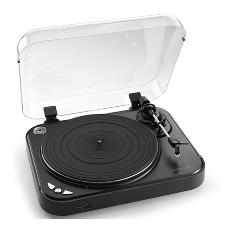
LENCO L-85 User manual

LENCO

LENCO L-85 User manual

LENCO LS-101 User manual

LENCO

LENCO LS-101 User manual

LENCO LS-410 User manual

LENCO

LENCO LS-410 User manual

LENCO L-80 USB - User manual

LENCO

LENCO L-80 USB - User manual

Popular Turntable manuals by other brands

Denver MRD-165 instruction manual

Denver

Denver MRD-165 instruction manual

Fenton RP162LED instruction manual

Fenton

Fenton RP162LED instruction manual

VPI Industries JMW 10 Setup and instruction manual

VPI Industries

VPI Industries JMW 10 Setup and instruction manual

NETGEAR NeoTV NTV200 quick start guide

NETGEAR

NETGEAR NeoTV NTV200 quick start guide

Welling F-700 operating instructions

Welling

Welling F-700 operating instructions

Technics SL-QD33 Service manual

Technics

Technics SL-QD33 Service manual

Teac TN-3B-SE/B owner's manual

Teac

Teac TN-3B-SE/B owner's manual

Radionette Tandberg TT 5000 Service manual

Radionette

Radionette Tandberg TT 5000 Service manual

jaytec DJT-2 instruction manual

jaytec

jaytec DJT-2 instruction manual

Power Dynamics 172.701 instruction manual

Power Dynamics

Power Dynamics 172.701 instruction manual

Audio Technica AT-LP2D-USB Installation and operation guide

Audio Technica

Audio Technica AT-LP2D-USB Installation and operation guide

Audio Technica AT-LP5 Installation and operation manual

Audio Technica

Audio Technica AT-LP5 Installation and operation manual

Retrophonic LY-116B user manual

Retrophonic

Retrophonic LY-116B user manual

Stanton STR8-80 user manual

Stanton

Stanton STR8-80 user manual

Audio Technica AT-LP60X user manual

Audio Technica

Audio Technica AT-LP60X user manual

Kenwood KD-492F instruction manual

Kenwood

Kenwood KD-492F instruction manual

Roadstar TTR-9645EBT user manual

Roadstar

Roadstar TTR-9645EBT user manual

Curtis rcd823 Specification sheet

Curtis

Curtis rcd823 Specification sheet

manuals.online logo
manuals.online logoBrands
  • About & Mission
  • Contact us
  • Privacy Policy
  • Terms and Conditions

Copyright 2025 Manuals.Online. All Rights Reserved.