manuals.online logo
Brands
  1. Home
  2. •
  3. Brands
  4. •
  5. Lennox
  6. •
  7. Air Conditioner
  8. •
  9. Lennox SCA Series Installation and operation manual

Lennox SCA Series Installation and operation manual

2007 Lennox Industries Inc.
Litho U.S.A.
Page 1
Corp. 0717−L5
SCA/SCB SERIES
Service Literature
10, 20 & 24 ton
35.2, 70.4 & 84.4 kW
Revised 10−2010
SCA/SCB
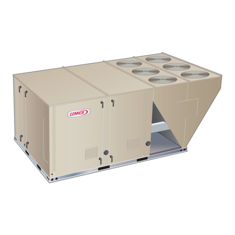
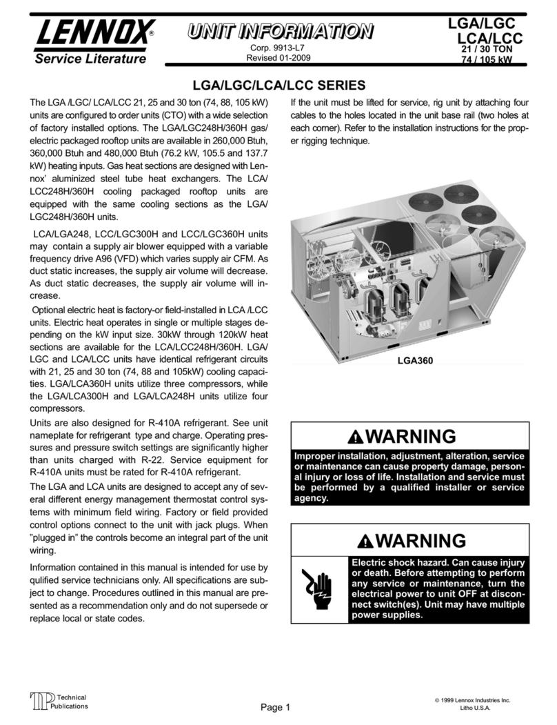
The SCA120, 240, 10 and 20 ton and SCB 288 24 ton, (35.2,
70.4 and 84.4 kW) units, are configure to order units (CTO)
with a wide selection of factory installed options. The SCA120
has a cooling capacity of 123,000 Btuh and the SCA240 has
gross a cooling capacity of 242,000 Btuh and the SCB has a
gross cooling capacity of 296,000 Btuh. All models are avai-
labe with factory installed multiple staged air volume (MSAV).
Units are designed for R410A refrigerant. See unit name-
plate. Operating pressures and pressure switch settings
are significantly higher than R22 charged units. Service
equipment must be rated for R410A.
Optional electric heat is factory installed in SCA units. Electric
heat operates in single or multiple stages depending on the
kW input size. 15 kW to 60 kW heat sections are available for
the SCA120 and 30, 60 and 90 kW heat sections are avail-
able for the SCA240/SCB288. SCA120 units utilize two com-
pressors, while SCA240/SCB288 units utilize four.
Information contained in this manual is intended for use by
qualified service technicians only. All specifications are sub-
ject to change. Procedures outlined in this manual are pre-
sented as a recommendation only and do not supersede or
replace local or state codes.
If the unit must be lifted for service, rig unit by attaching four
cables to the holes located in the unit base rail (two holes at
each corner). Refer to the installation instructions for the prop-
er rigging technique.
WARNING
Improper installation, adjustment, alteration, service
or maintenance can cause property damage, person-
al injury or loss of life. Installation and service must
be performed by a qualified installer or service
agency.
WARNING
Electric shock hazard. Can cause injury
or death. Before attempting to perform
any service or maintenance, turn the
electrical power to unit OFF at discon-
nect switch(es). Unit may have multiple
power supplies.
CAUTION
Danger of sharp metallic edges. Can cause injury.
Take care when servicing unit to avoid accidental
contact with sharp edges.
SCA120
SCA240/SCB288
Table of Contents
Options / Accessories Page 2. . . . . . . . . . . . . . .
Specifications Page 4. . . . . . . . . . . . . . . . . . . . . .
Blower Data Page 8. . . . . . . . . . . . . . . . . . . . . . .
Electrical / Electric Heat Data Page 12. . . . . . . .
Parts Arrangement Page 15. . . . . . . . . . . . . . . . .
I Unit Components Page 18. . . . . . . . . . . . . . . . . .
II Placement and Installation Page 36. . . . . . . . .
III Charging Page 36. . . . . . . . . . . . . . . . . . . . . . . .
IV System Service Checks Page 38. . . . . . . . . .
V Maintenance Page 38. . . . . . . . . . . . . . . . . . . . .
VI Accessories Page 39. . . . . . . . . . . . . . . . . . .
VII Wiring and Operation Sequence Page 42. . .
Page 2
OPTIONS / ACCESSORIES
Item Description Model
Number
Catalog
Number 120 240 288
COOLING SYSTEM
Condensate Drain Trap EPDM - C1TRAP30121- 43W45 OX OX OX
Copper - LTACDKC09/36 76M19 OX OX
Corrosion Protection Condenser Section Factory O O O
Evaporator Section Factory O O O
Both Sections Factory O O O
Drain Pan Overow Switch 60W18 XXX
ELECTRICAL
Voltage
60 hz
208/230V - 3 phase Factory O O O
460V - 3 phase Factory O O O
575V - 3 phase Factory O O O
BLOWER - SUPPLY AIR
Constant Air Volume 1.5 hp Factory
3 hp Factory O
5 hp Factory O O
7.5 hp Factory O O
MSAV™ (multi-stage air volume) supply fan option 3 hp Factory O
5 hp Factory O O
7.5 hp Factory O O
CABINET
Coil Guards S1GARD22101 50W67
S1GARD22111 50W68 X
C1GARD29121 43W47 X X
Hail Guards S1GARD10101 47W20
S1GARD10111 47W21 X
C1GARD19121 43W46 X X
CONTROLS
Commercial Controls
CPC Multiex 810-3062 Factory O O O
Danfoss RTC Control Factory O O O
IMC BACnet®Module Factory O O O
IMC LonTalk®Module Factory O O O
Novar 2024 Factory O O O
Novar 2051 Factory O O O
L Connection® Network Factory O O O
Fresh Air Tempering C0SNDC03AE1- 45L78 XXX
1Smoke Detector Supply Factory O O O
Return Factory O O O
ELECTRIC HEAT
210 kW Factory
15 kW Factory O
220 kW Factory O O
30 kW Factory O O O
240 kW Factory O O
45 kW Factory O
60 kW Factory O O O
280 kW Factory O
90 kW Factory O O
1 Factory installed smoke detectors must be ordered for use with either 115V or 24V external power supply only.
2Available for 460V only.
NOTE - Catalog and model numbers shown are for ordering eld installed accessories.
OX - Congure To Order (Factory Installed) or Field Installed
O = Congure To Order (Factory Installed)
X = Field Installed
Page 3
OPTIONS / ACCESSORIES
Item Description Model
Number
Catalog
Number 120 240 288
INDOOR AIR QUALITY
Air Filters
Healthy Climate® High Efciency Air Filters MERV 8 Factory O O
MERV11- 3 C1FLTR50D-1- 97L88 OX OX
MERV 15- 1 C1FLTR50101 28W03
2C1FLTR50EA1 28W02 X
3C1FLTR50D- 28W06 X X
Indoor Air Quality (CO2) Sensors
Sensor - Wall-mount, off-white plastic cover with LCD display C0SNSR50AE1L 77N39 XXX
Sensor - Wall-mount, off-white plastic cover, no display C0SNSR52AE1L 87N53 XXX
Sensor - Black plastic case with LCD display, rated for plenum mounting C0SNSR51AE1L 87N52 XXX
Sensor - Wall-mount, black plastic case, no display, rated
for plenum mounting
C0MISC19AE1 87N54 XXX
CO2 Sensor Duct Mounting Kit - for downow applications C0MISC19AE1- 85L43 XXX
Aspiration Box - for duct mounting non-plenum rated CO2sensors
(87N53 or 77N39)
C0MISC16AE1- 90N43 XXX
ECONOMIZER
Economizer with Hood and Barometric Relief Damper (Global Sensor, eld provided) Factory O O O
Economizer Controls
Differential Enthalpy C1SNSR07AE1- 86M33 OX OX OX
Single Enthalpy C1SNSR06AE1- 86M32 OX OX OX
OUTDOOR AIR
Manual Outdoor Air
Damper with Hood
Mesh/Wire Screen Filter Furnished Factory O O O
Bird Screen Furnished Factory O O O
Motorized Outdoor Air
Damper with Hood
Mesh/Wire Screen Filter Furnished Factory O O O
POWER EXHAUST
Standard Static Factory O O O
ROOF CURBS - DOWNFLOW
14 in. height S7CURB10101- 30W03
S1CURB10111- 30W06 X
Full Perimeter - S6CURB10121- 30W15 X X
24 in. height S7CURB11101- 30W04
S1CURB11111- 30W07 X
Full Perimeter - S6CURB11121- 30W16 X X
LTL PACKAGING Factory O O O
1 16 x 20 x 2 - Order 4 per unit
2 16 x 25 x 2 - Order 6 per unit
3 20 x 20 x 2 - order 12 per unit
NOTE - Catalog and model numbers shown are for ordering eld installed accessories.
OX - Congure To Order (Factory Installed) or Field Installed
O = Congure To Order (Factory Installed)
X = Field Installed
Page 4
SPECIFICATIONS 10 TON
General
Data
Nominal Tonnage 10 Ton 10 Ton
Model No. SCA120H4B SCA120H4M
Blower Type Constant Air Volume MSAV (Multi-Stage Air
Volume) Supply Fan Option
Efciency Type High High
Cooling
Performance
Gross Cooling Capacity - Btuh 123,000 123,000
1Net Cooling Capacity - Btuh 119,000 119,000
AHRI Rated Air Flow - cfm 3700 3700
Total Unit Power 9.7 9.8
1EER (Btuh/Watt) 12.3 12.1
2IEER (Btuh/Watt) 12.8 15.2
Refrigerant Charge Furnished
R-410A
Circuit 1 22 lbs. 8 oz. 24 lbs. 0 oz.
Circuit 2 21 lbs. 0 oz. 21 lbs. 8 oz.
3Sound Rating Number (dB) 88 88
Electric Heat Options Available See page 2
Compressor Type (No.) Scroll (2) Scroll (2)
Condenser Coil Net face area - sq. ft. 47.1 47.1
Tube diameter - in. 3/8 3/8
Number of rows 3 3
Fins per inch 14 14
Condenser
Fan(s)
Motor horsepower (3) 1/3 (3) 1/3
Motor rpm 1075 1075
Total Motor watts 940 940
Diameter - in. (3) 24 (3) 24
Number of blades 3 3
Total air volume - cfm 11,800 11,800
Evaporator Coil Net face area - sq. ft. 15.6 15.6
Tube diameter - in. 3/8 3/8
Number of rows 4 4
Fins per inch 14 14
Drain connection - no. & size (1) 1 (1) 1
Expansion device type Thermostatic Expansion Valve
4Indoor
Blower
Nominal motor output 3 3
Maximum usable motor output 3.45 - - -
RPM Range (Standard Static) Drive #1 - 660-900 rpm Drive #3 - 350-1050 rpm
RPM Range (High Static) Drive #2 - 865-1080 rpm - - -
Wheel nominal diameter x width - in. (1) 15 x 15 (1) 15 x 15
Filters Type of lter MERV 7 or equivalent
Number and size - in. (6) 16 x 25 x 2
Electrical characteristics 208/230V, 460V, or 575V - 60 hertz - 3 phase
NOTE - Net capacity includes evaporator blower motor heat deduction. Gross capacity does not include evaporator blower motor heat deduction.
1 Certied in accordance with the ULE certication program, which is based on AHRI Standard 340/360, 95°F outdoor air temperature and 80°F db/67°F wb entering
evaporator air; minimum external duct static pressure.
2 Integrated Energy Efciency Ratio certied and tested according to AHRI Standard 340/360.
3 Sound Rating Number rated in accordance with test conditions included in AHRI Standard 270.
4 Using total air volume and system static pressure requirements determine from blower performance tables rpm and motor output required. Maximum usable output of
motors furnished are shown. In Canada, nominal motor output is also maximum usable motor output. If motors of comparable output are used, be sure to keep within
the service factor limitations outlined on the motor nameplate.
Page 5
SPECIFICATIONS 20 TON
General
Data
Nominal Tonnage 20 Ton 20 Ton
Model No. SCA240H4B SCA240H4M
Blower Type Constant Air Volume MSAV (Multi-Stage Air
Volume) Supply Fan Option
Efciency Type High High
Cooling
Performance
Gross Cooling Capacity - Btuh 242,000 242,000
Net Cooling Capacity - Btuh 1236,000 2236,000
AHRI Rated Air Flow - cfm 6500 6500
Total Unit Power - kW 18.7 18.7
EER (Btuh/Watt) 112.6 212.6
3IEER (Btuh/Watt) 14.3 16.8
Refrigerant Charge Furnished
R-410A
Circuit 1 17 lbs. 0 oz. 16 lbs. 0 oz.
Circuit 2 17 lbs. 0 oz. 16 lbs. 0 oz.
Circuit 3 17 lbs. 0 oz. 15 lbs. 0 oz.
Circuit 4 17 lbs. 0 oz. 15 lbs. 0 oz.
4Sound Rating Number (dB) 92 92
Electric Heat Options Available See page 2
Compressor Type (No.) Scroll (4) Scroll (4)
Condenser Coil Net face area - sq. ft. 70.6 70.6
Tube diameter - in. 3/8 3/8
Number of rows 3 3
Fins per inch 14 14
Condenser
Fan(s)
Motor horsepower (6) 1/3 (6) 1/3
Motor rpm 1075 1075
Total Motor watts 1900 1900
Diameter - in. (6) 24 (6) 24
Number of blades 3 3
Total air volume - cfm 22,500 22,500
Evaporator Coil Net face area - sq. ft. 33.3 33.3
Tube diameter - in. 3/8 3/8
Number of rows 3 3
Fins per inch 14 14
Drain connection - no. & size (1) 1 (1) 1
Expansion device type Thermostatic Expansion Valve
5Indoor
Blower
Nominal motor HP 5 5
Maximum usable motor HP 5.75 - - -
RPM Range (Standard Static) Drive #2 - 520-685 rpm Drive #4 - 282-846 rpm
RPM Range (High Static) Drive #3 - 685-865 rpm - - -
Nominal motor HP 7.5 7.5
Maximum usable motor HP 8.63 - - -
RPM Range Drive #6 - 770-965 rpm Drive #7 - 322-965 rpm
Wheel nominal diameter x width - in. (2) 18 x 15 (2) 18 x 15
Filters Type of lter MERV 7 or equivalent
Number and size - in. (12) 20 x 20 x 2
Electrical characteristics 208/230V, 460V, or 575V - 60 hertz - 3 phase
NOTE - Net capacity includes evaporator blower motor heat deduction. Gross capacity does not include evaporator blower motor heat deduction.
1 Certied in accordance with the ULE certication program, which is based on AHRI Standard 340/360, 95°F outdoor air temperature and 80°F db/67°F wb entering
evaporator air; minimum external duct static pressure.
2 Rated at test conditions included in AHRI Standard 340/360, 95°F outdoor air temperature and 80°F db/67°F wb entering evaporator air; minimum external duct static
pressure.
3 Integrated Energy Efciency Ratio certied and tested according to AHRI Standard 340/360.
4 Sound Rating Number rated in accordance with test conditions included in AHRI Standard 270.
5 Using total air volume and system static pressure requirements determine from blower performance tables rpm and motor output required. Maximum usable output of
motors furnished are shown. In Canada, nominal motor output is also maximum usable motor output. If motors of comparable output are used, be sure to keep within
the service factor limitations outlined on the motor nameplate.
Page 6
SPECIFICATIONS 24 TON
General
Data
Nominal Tonnage 24 Ton 24 Ton
Model No. SCB288H4B SCB288H4M
Blower Type Constant Air Volume MSAV (Multi-Stage Air
Volume) Supply Fan Option
Efciency Type High High
Cooling
Performance
Gross Cooling Capacity - Btuh 296,000 296,000
Net Cooling Capacity - Btuh 288,000 288,000
AHRI Rated Air Flow - cfm 7700 7700
Total Unit Power - kW 24.8 24.8
1EER (Btuh/Watt) 11.6 11.6
2IEER (Btuh/Watt) 12.8 14.2
Refrigerant Charge Furnished
R-410A
Circuit 1 16 lbs. 0 oz. 15 lbs. 8 oz.
Circuit 2 16 lbs. 0 oz. 15 lbs. 8 oz.
Circuit 3 16 lbs. 0 oz. 15 lbs. 8 oz.
Circuit 4 16 lbs. 0 oz. 15 lbs. 8 oz.
3Sound Rating Number (dB) 94 94
Electric Heat Options Available See page 2
Compressor Type (No.) Scroll (4) Scroll (4)
Condenser Coil Net face area - sq. ft. 70.6 70.6
Tube diameter - in. 3/8 3/8
Number of rows 3 3
Fins per inch 14 14
Condenser
Fan(s)
Motor horsepower (6) 1/3 (6) 1/3
Motor rpm 1075 1075
Total Motor watts 1900 1900
Diameter - in. (6) 24 (6) 24
Number of blades 3 3
Total air volume - cfm 24,500 24,500
Evaporator Coil Net face area - sq. ft. 33.3 33.3
Tube diameter - in. 3/8 3/8
Number of rows 3 3
Fins per inch 14 14
Drain connection - no. & size (1) 1 (1) 1
Expansion device type Thermostatic Expansion Valve
4Indoor
Blower
Nominal motor HP 5 5
Maximum usable motor HP 5.75 - - -
RPM Range (Standard Static) Drive #2 - 520-685 rpm Drive #4 - 282-846 rpm
RPM Range (High Static) Drive #3 - 685-865 rpm - - -
Nominal motor HP 7.5 7.5
Maximum usable motor HP 8.63 - - -
RPM Range Drive #6 - 770-965 rpm Drive #7 - 322-965 rpm
Wheel nominal diameter x width - in. (2) 18 x 15 (2) 18 x 15
Filters Type of lter MERV 7 or equivalent
Number and size - in. (12) 20 x 20 x 2
Electrical characteristics 208/230V, 460V, or 575V - 60 hertz - 3 phase
NOTE - Net capacity includes evaporator blower motor heat deduction. Gross capacity does not include evaporator blower motor heat deduction.
1 Rated at test conditions included in AHRI Standard 340/360, 95°F outdoor air temperature and 80°F db/67°F wb entering evaporator air; minimum external duct static
pressure.
2 Integrated Energy Efciency Ratio certied and tested according to AHRI Standard 340/360.
3 Sound Rating Number rated in accordance with test conditions included in AHRI Standard 270.
4 Using total air volume and system static pressure requirements determine from blower performance tables rpm and motor output required. Maximum usable output of
motors furnished are shown. In Canada, nominal motor output is also maximum usable motor output. If motors of comparable output are used, be sure to keep within
the service factor limitations outlined on the motor nameplate.
Page 7
SPECIFICATIONS - INTEGRATED MODULAR CONTROLLER (IMC)
Operating Environment Temperature: –40°F to 155°F
Humidity: 10% - 95% RH, Non- Condensing
Power Requirements 24VAC (+/–25%), 50/60Hz
4.8 VA for IMC maximum
14.4 VA for IMC w/all expansion boards Maximum
Memory Type Re-programmable Flash
Device Commissioning Auto-poll (real plug and play)
Unit type Electric/Electric, Gas/Electric & Heat Pumps (Rooftops), CAV, MSAV (Multi-Stage
Air Volume) and VAV units
Cooling stages 4
Heating stages 4
Modulating Gas Valves 2
Electronic Congure To Order Parameters 239
Alarm Codes 107
Alarm Codes Stored 84
Display Type 3 Digit Seven Segment Red LED
Indicator LEDs 1- Heartbeat on each board
1- Bus transmit
1 - Bus receive
1- each for Y1,Y2,W1,W2,G,OCP
Dimensions IMC Main Board:
Height: 1-1/2 in., Width: 12 in., Depth: 7 in.
#2 Compressor Module,
#2 Compressor and Reversing Valve Module
#3 and 4 Compressor Module,
#2 Electric Heat Module,
#2 Gas Heat Module,
Economizer Module,
Humiditrol Module
VAV, Modulating Gas and I/O Modules:
Height: 7/8 in., Width: 3-3/4 in., Depth: 4 in.
Weight 2 lbs. for IMC w/all expansion boards installed
Cable Type SysBus - Lennox yellow COMM cable:
C0MISC00AE1- (27M19) (500 ft. box),
C0MISC04AE1- (94L63) (1000 ft. box),
C0MISC01AE1- (68M25) (2500 ft. roll)
ZoneBus - Lennox purple COMM cable:
C0MISC05AE1- (23W99) (500 ft. box)
C0MISC06AE1- (24W00) (1000 ft. box)
C0MISC07AE1- (24W01) (2500 ft. roll)
Non-Communicating Zone Sensor
Non-Communicating RH Sensor
Non-Communicating CO2 Sensor
Page 8
BLOWER DATA
SCA120H BLOWER PERFORMANCE
NOTE - Blower Table Includes Resistance For Base Unit With Electric Heat, Wet Indoor Coil And Air Filters In Place.
NOTE - Minimum 3800 cfm with electric heat.
See Blower Motor / Drive Kit Table on page 11 for Motor HP and Drive Kit RPM Ranges Available.
Air
Volume
cfm
TOTAL STATIC PRESSURE - In. w.g.
0.1 0.2 0.3 0.4 0.5 0.6 0.7 0.8 0.9 1.0 1.1 1.2 1.3
RPM BHP RPM BHP RPM BHP RPM BHP RPM BHP RPM BHP RPM BHP RPM BHP RPM BHP RPM BHP RPM BHP RPM BHP RPM BHP
2000 472 0.13 503 0.26 534 0.40 566 0.54 598 0.68 630 0.81 662 0.93 695 1.03 726 1.11 759 1.18 792 1.25 828 1.34 866 1.45
2200 484 0.23 514 0.36 545 0.50 576 0.64 608 0.77 640 0.90 672 1.01 703 1.11 735 1.19 767 1.26 800 1.34 837 1.43 875 1.54
2400 497 0.33 526 0.46 557 0.60 588 0.73 619 0.86 650 0.99 682 1.10 713 1.19 745 1.27 777 1.35 811 1.43 847 1.53 885 1.64
2600 510 0.44 539 0.57 569 0.70 600 0.83 631 0.96 662 1.08 693 1.19 725 1.29 756 1.37 788 1.44 822 1.53 858 1.63 896 1.75
2800 524 0.55 553 0.68 583 0.81 613 0.94 644 1.07 675 1.19 706 1.29 737 1.39 768 1.47 801 1.55 835 1.64 871 1.75 908 1.87
3000 538 0.67 567 0.79 597 0.93 627 1.06 658 1.18 689 1.30 720 1.41 751 1.50 782 1.58 815 1.67 849 1.76 884 1.87 922 1.99
3200 554 0.79 583 0.92 612 1.05 643 1.18 673 1.31 704 1.42 735 1.53 766 1.62 797 1.71 830 1.79 863 1.89 899 2.00 936 2.12
3400 570 0.92 599 1.05 629 1.18 659 1.31 690 1.44 721 1.55 752 1.66 782 1.75 814 1.84 846 1.93 879 2.03 914 2.13 951 2.25
3600 588 1.06 616 1.19 646 1.32 677 1.45 708 1.58 739 1.69 769 1.80 800 1.89 831 1.98 863 2.07 896 2.17 931 2.28 967 2.39
3800 606 1.21 635 1.34 665 1.48 696 1.61 727 1.73 758 1.85 788 1.95 818 2.04 849 2.13 881 2.22 913 2.32 948 2.42 983 2.53
4000 626 1.37 655 1.50 685 1.64 716 1.77 747 1.90 778 2.01 808 2.10 837 2.20 868 2.28 899 2.38 932 2.47 965 2.57 1000 2.68
4200 647 1.54 676 1.68 707 1.82 738 1.95 769 2.07 799 2.18 828 2.27 857 2.36 887 2.45 918 2.54 950 2.63 983 2.73 1018 2.84
4400 669 1.72 699 1.87 730 2.01 761 2.14 791 2.25 820 2.35 849 2.44 878 2.53 908 2.61 938 2.70 969 2.79 1002 2.89 1036 2.99
4600 693 1.92 724 2.07 755 2.21 785 2.34 814 2.45 842 2.54 871 2.62 899 2.71 928 2.79 958 2.87 989 2.96 1021 3.06 1054 3.16
4800 718 2.14 749 2.29 780 2.43 809 2.54 837 2.64 865 2.73 893 2.81 920 2.88 949 2.96 979 3.04 1009 3.13 1041 3.22 1073 3.32
NOTE - MSAV (Multi-Stage Air Volume) Supply Fan Option drive is capable of 350 - 1050 rpm.
Page 9
BLOWER DATA
SCA240H BLOWER PERFORMANCE
NOTE - Blower Table Includes Resistance For Base Unit With Electric Heat, Wet Indoor Coil And Air Filters In Place.
NOTE - Minimum 8000 cfm with electric heat.
See Blower Motor / Drive Kit Table on page 11 for Motor HP and Drive Kit RPM Ranges Available.
Air
Volume
cfm
TOTAL STATIC PRESSURE - In. w.g.
0.1 0.2 0.3 0.4 0.5 0.6 0.7 0.8 0.9 1.0 1.1 1.2 1.3
RPM BHP RPM BHP RPM BHP RPM BHP RPM BHP RPM BHP RPM BHP RPM BHP RPM BHP RPM BHP RPM BHP RPM BHP RPM BHP
2000 255 0.33 310 0.48 366 0.63 416 0.74 458 0.81 498 0.89 537 0.99 573 1.10 607 1.22 642 1.35 677 1.49 712 1.65 749 1.80
2200 258 0.37 313 0.52 369 0.67 418 0.78 460 0.85 500 0.92 538 1.03 574 1.15 609 1.27 643 1.40 678 1.55 714 1.70 751 1.86
2400 261 0.40 316 0.56 372 0.70 421 0.81 462 0.88 502 0.96 540 1.07 576 1.19 610 1.32 645 1.45 680 1.60 716 1.76 753 1.92
2600 265 0.44 319 0.60 375 0.74 423 0.85 464 0.92 505 1.00 542 1.11 578 1.24 612 1.37 646 1.51 682 1.66 718 1.82 755 1.98
2800 268 0.48 322 0.63 378 0.77 426 0.89 467 0.95 507 1.04 545 1.16 580 1.29 614 1.42 648 1.56 684 1.72 720 1.88 757 2.04
3000 272 0.51 326 0.67 382 0.81 429 0.92 470 0.99 510 1.09 547 1.21 582 1.34 616 1.48 650 1.63 686 1.78 723 1.94 759 2.10
3200 276 0.55 330 0.71 386 0.85 433 0.96 473 1.03 513 1.13 550 1.26 584 1.40 618 1.54 652 1.69 688 1.85 725 2.01 762 2.16
3400 280 0.59 335 0.74 391 0.88 437 1.00 477 1.08 516 1.18 552 1.32 587 1.46 620 1.61 655 1.76 691 1.91 727 2.07 764 2.23
3600 285 0.62 340 0.78 395 0.92 441 1.04 480 1.12 520 1.24 555 1.38 589 1.53 623 1.67 657 1.83 693 1.98 730 2.14 767 2.30
3800 290 0.66 345 0.81 400 0.96 445 1.08 484 1.17 523 1.29 559 1.44 592 1.59 626 1.74 660 1.90 696 2.06 733 2.22 770 2.38
4000 296 0.69 351 0.85 406 0.99 449 1.12 488 1.22 527 1.35 562 1.51 595 1.66 629 1.82 663 1.97 699 2.14 736 2.30 773 2.46
4200 301 0.73 358 0.88 411 1.03 453 1.17 493 1.27 531 1.41 565 1.57 599 1.73 632 1.89 666 2.05 702 2.22 739 2.39 776 2.56
4400 308 0.76 364 0.92 416 1.07 458 1.22 497 1.33 534 1.48 569 1.64 602 1.81 635 1.97 670 2.14 706 2.31 743 2.48 779 2.66
4600 315 0.80 371 0.95 422 1.12 463 1.26 502 1.39 539 1.54 573 1.71 606 1.88 639 2.05 673 2.22 710 2.40 746 2.58 783 2.76
4800 322 0.83 378 0.99 427 1.16 468 1.32 507 1.45 543 1.62 577 1.79 609 1.96 642 2.14 677 2.32 714 2.50 751 2.69 788 2.87
5000 330 0.86 386 1.03 433 1.21 473 1.38 512 1.52 547 1.69 581 1.87 613 2.05 647 2.22 682 2.41 718 2.60 755 2.79 792 2.98
5200 338 0.89 393 1.07 438 1.27 478 1.44 517 1.59 551 1.77 585 1.95 617 2.13 651 2.32 686 2.50 722 2.70 759 2.89 796 3.08
5400 346 0.92 400 1.12 444 1.33 484 1.51 522 1.67 556 1.86 589 2.04 622 2.23 655 2.41 690 2.60 727 2.79 764 2.98 801 3.17
5600 355 0.96 407 1.17 450 1.40 490 1.58 528 1.76 561 1.96 594 2.14 626 2.33 660 2.51 695 2.70 732 2.89 769 3.08 806 3.27
5800 364 1.00 414 1.23 457 1.47 496 1.65 533 1.85 566 2.06 599 2.24 631 2.43 665 2.61 701 2.81 737 3.00 774 3.19 811 3.38
6000 372 1.04 422 1.29 463 1.54 502 1.73 539 1.95 571 2.17 604 2.35 636 2.53 670 2.72 706 2.91 743 3.11 779 3.30 816 3.50
6200 381 1.08 429 1.36 470 1.62 508 1.82 544 2.05 576 2.28 609 2.46 641 2.64 676 2.82 712 3.02 749 3.22 785 3.42 822 3.62
6400 390 1.14 437 1.44 477 1.71 515 1.92 550 2.16 582 2.39 614 2.57 647 2.74 682 2.93 718 3.14 755 3.34 792 3.54 828 3.75
6600 399 1.20 444 1.53 484 1.80 521 2.02 556 2.28 587 2.51 620 2.68 653 2.85 688 3.04 725 3.25 762 3.46 798 3.67 835 3.87
6800 408 1.27 452 1.62 491 1.89 528 2.13 562 2.40 593 2.63 625 2.80 659 2.96 694 3.15 731 3.37 768 3.58 805 3.80 842 4.01
7000 417 1.35 460 1.71 498 1.99 535 2.24 568 2.52 599 2.74 631 2.91 665 3.08 700 3.27 737 3.48 775 3.70 812 3.92 848 4.14
7200 426 1.45 467 1.82 505 2.10 541 2.36 574 2.65 606 2.86 638 3.02 671 3.19 707 3.39 744 3.60 781 3.83 818 4.05 855 4.27
7400 435 1.55 475 1.93 513 2.22 548 2.49 580 2.77 612 2.98 644 3.14 677 3.31 713 3.50 750 3.72 788 3.94 825 4.17 861 4.39
7600 444 1.67 483 2.05 520 2.34 555 2.62 587 2.90 618 3.10 650 3.26 684 3.43 719 3.62 756 3.84 794 4.06 831 4.29 868 4.51
7800 452 1.80 491 2.18 528 2.47 562 2.75 594 3.02 625 3.22 657 3.38 690 3.55 726 3.74 763 3.96 800 4.18 837 4.40 874 4.62
8000 461 1.93 500 2.31 536 2.61 570 2.89 601 3.15 632 3.35 664 3.51 697 3.67 732 3.87 769 4.08 806 4.30 843 4.52 880 4.74
8200 470 2.08 508 2.45 544 2.75 577 3.03 608 3.29 639 3.47 671 3.63 704 3.80 739 3.99 775 4.20 812 4.42 849 4.64 886 4.86
8400 479 2.23 516 2.60 552 2.90 585 3.18 615 3.42 646 3.60 678 3.76 711 3.93 746 4.11 782 4.32 819 4.54 855 4.76 892 4.98
8600 488 2.39 525 2.76 560 3.05 592 3.33 623 3.56 653 3.74 685 3.89 718 4.06 752 4.24 788 4.44 825 4.66 862 4.88 898 5.10
8800 498 2.56 533 2.91 568 3.21 600 3.48 630 3.70 661 3.87 692 4.02 725 4.19 759 4.37 795 4.57 831 4.78 868 5.00 904 5.21
9000 507 2.73 542 3.08 576 3.37 608 3.63 638 3.85 668 4.01 699 4.16 732 4.32 766 4.50 802 4.69 838 4.90 874 5.12 911 5.33
9200 516 2.91 551 3.25 584 3.53 616 3.78 645 3.99 676 4.15 707 4.29 739 4.45 773 4.63 808 4.82 844 5.03 881 5.24 917 5.46
9400 526 3.09 560 3.42 593 3.69 623 3.94 653 4.13 683 4.28 714 4.43 746 4.58 780 4.76 815 4.95 851 5.15 887 5.36 923 5.58
9600 535 3.27 569 3.59 601 3.86 631 4.10 661 4.28 691 4.42 721 4.56 753 4.72 787 4.89 822 5.08 858 5.28 894 5.49 930 5.70
Page 10
BLOWER DATA
SCB288H BLOWER PERFORMANCE
NOTE - Blower Table Includes Resistance For Base Unit With Gas Heat, Wet Indoor Coil And Air Filters In Place.
NOTE - Minimum 8000 cfm with electric heat.
See Blower Motor / Drive Kit Table on page 11 for Motor HP and Drive Kit RPM Ranges Available.
Air
Volume
cfm
TOTAL STATIC PRESSURE - In. w.g.
0.2 0.3 0.4 0.5 0.6 0.7 0.8 0.9 1.0 1.1 1.2 1.3
RPM BHP RPM BHP RPM BHP RPM BHP RPM BHP RPM BHP RPM BHP RPM BHP RPM BHP RPM BHP RPM BHP RPM BHP
2400 327 0.42 377 0.54 428 0.65 479 0.75 527 0.87 568 0.99 599 1.10 628 1.22 659 1.31 690 1.40 719 1.51 746 1.66
2600 330 0.44 379 0.57 430 0.68 481 0.79 529 0.91 570 1.03 601 1.15 630 1.27 661 1.37 692 1.46 721 1.58 748 1.72
2800 333 0.46 381 0.59 432 0.71 483 0.83 531 0.95 572 1.08 603 1.20 632 1.32 664 1.43 694 1.53 723 1.65 750 1.79
3000 336 0.49 384 0.62 434 0.75 485 0.87 534 1.00 574 1.13 605 1.26 634 1.38 666 1.49 697 1.59 725 1.71 752 1.86
3200 339 0.51 387 0.65 437 0.79 488 0.91 536 1.05 576 1.18 608 1.31 637 1.44 668 1.55 699 1.66 727 1.78 754 1.93
3400 343 0.54 391 0.69 440 0.83 491 0.96 539 1.10 579 1.24 610 1.37 639 1.50 670 1.62 701 1.73 730 1.86 756 2.00
3600 346 0.58 394 0.72 444 0.87 495 1.01 542 1.15 581 1.29 612 1.43 641 1.57 672 1.69 703 1.80 732 1.93 758 2.08
3800 351 0.61 398 0.76 448 0.91 498 1.06 545 1.20 584 1.35 614 1.50 643 1.64 675 1.76 705 1.88 734 2.01 760 2.16
4000 355 0.65 403 0.81 452 0.96 502 1.11 549 1.26 587 1.41 617 1.56 645 1.71 677 1.84 708 1.96 736 2.09 762 2.24
4200 360 0.69 407 0.85 456 1.01 506 1.16 553 1.32 590 1.47 619 1.63 648 1.78 679 1.91 710 2.04 739 2.17 765 2.32
4400 365 0.73 412 0.90 461 1.06 511 1.22 556 1.38 593 1.54 622 1.70 650 1.86 682 1.99 713 2.12 741 2.25 767 2.40
4600 370 0.78 417 0.95 466 1.12 516 1.28 560 1.44 597 1.61 625 1.78 653 1.94 684 2.08 715 2.2 744 2.34 769 2.49
4800 375 0.83 422 1.01 471 1.18 520 1.34 565 1.50 600 1.68 628 1.85 656 2.02 687 2.16 718 2.29 746 2.43 772 2.59
5000 381 0.89 428 1.06 477 1.23 525 1.40 569 1.57 604 1.75 631 1.93 658 2.10 690 2.25 720 2.38 749 2.52 774 2.68
5200 387 0.94 434 1.12 483 1.30 531 1.47 573 1.64 607 1.83 634 2.02 661 2.19 692 2.34 723 2.48 751 2.62 777 2.78
5400 393 1.00 440 1.19 489 1.36 536 1.53 577 1.72 610 1.91 636 2.10 664 2.28 695 2.43 726 2.57 754 2.71 780 2.87
5600 400 1.07 447 1.25 495 1.43 541 1.61 581 1.80 613 2.00 639 2.19 667 2.37 698 2.53 729 2.66 757 2.81 783 2.98
5800 407 1.13 454 1.32 501 1.50 546 1.68 585 1.88 616 2.09 642 2.29 670 2.47 701 2.62 732 2.76 760 2.91 786 3.08
6000 414 1.20 461 1.39 507 1.57 551 1.76 589 1.97 619 2.18 645 2.38 673 2.57 704 2.72 735 2.86 763 3.01 788 3.19
6200 422 1.27 468 1.46 514 1.65 556 1.85 593 2.06 622 2.27 648 2.48 676 2.66 707 2.82 738 2.96 766 3.12 792 3.31
6400 429 1.34 475 1.53 520 1.73 561 1.94 596 2.16 625 2.37 651 2.58 679 2.76 711 2.92 742 3.07 770 3.23 795 3.43
6600 437 1.41 482 1.61 526 1.82 566 2.04 600 2.26 628 2.47 655 2.68 683 2.86 715 3.02 745 3.18 773 3.35 798 3.55
6800 445 1.49 490 1.69 532 1.91 571 2.14 603 2.37 632 2.58 658 2.78 687 2.97 718 3.13 749 3.29 777 3.47 801 3.68
7000 453 1.56 497 1.78 538 2.01 575 2.25 607 2.48 635 2.69 662 2.88 691 3.07 722 3.24 753 3.41 780 3.59 805 3.82
7200 461 1.64 504 1.87 544 2.12 580 2.37 611 2.60 639 2.80 666 2.99 695 3.18 727 3.35 757 3.53 784 3.72 808 3.96
7400 470 1.73 511 1.97 550 2.23 584 2.49 615 2.72 642 2.92 670 3.10 700 3.29 731 3.47 761 3.65 788 3.86 812 4.10
7600 478 1.82 519 2.08 556 2.36 589 2.62 619 2.85 646 3.04 674 3.22 704 3.41 735 3.59 765 3.78 792 4.00 815 4.25
7800 486 1.92 526 2.20 562 2.48 594 2.75 623 2.98 651 3.16 679 3.34 709 3.53 740 3.72 769 3.92 796 4.15 819 4.41
8000 494 2.03 533 2.32 568 2.62 599 2.89 627 3.11 655 3.29 684 3.46 714 3.65 745 3.85 774 4.07 800 4.30 823 4.57
8200 502 2.14 540 2.44 574 2.76 605 3.03 633 3.25 660 3.42 689 3.59 719 3.79 750 3.99 778 4.22 804 4.46 826 4.73
8400 510 2.26 547 2.58 581 2.89 611 3.17 638 3.38 666 3.56 694 3.72 724 3.93 755 4.14 783 4.37 808 4.63 830 4.90
8600 518 2.39 554 2.71 587 3.04 617 3.31 644 3.52 671 3.69 700 3.86 730 4.07 759 4.30 787 4.53 812 4.80 834 5.08
8800 526 2.52 561 2.86 594 3.19 623 3.46 650 3.66 677 3.83 705 4.01 735 4.22 764 4.45 792 4.70 816 4.97 838 5.26
9000 534 2.66 568 3.01 600 3.34 629 3.61 655 3.81 683 3.98 711 4.16 740 4.38 769 4.62 796 4.87 820 5.15 842 5.44
9200 541 2.81 575 3.17 606 3.50 634 3.77 661 3.96 688 4.13 717 4.31 746 4.54 775 4.78 801 5.05 825 5.34 846 5.64
9400 548 2.97 582 3.34 613 3.67 640 3.93 667 4.12 694 4.29 723 4.47 751 4.70 780 4.96 806 5.23 829 5.53 851 5.84
9600 556 3.14 588 3.51 619 3.84 646 4.10 673 4.28 700 4.45 728 4.64 757 4.88 785 5.14 810 5.42 834 5.73 855 6.04
9800 563 3.31 595 3.68 625 4.02 652 4.26 679 4.45 706 4.62 734 4.81 763 5.06 790 5.33 815 5.62 838 5.93 859 6.25
10,000 569 3.48 601 3.86 631 4.19 658 4.44 685 4.62 712 4.79 740 4.99 768 5.24 795 5.52 820 5.82 843 6.14 864 6.47
10,200 576 3.66 608 4.04 637 4.37 664 4.61 691 4.79 718 4.97 746 5.17 774 5.43 800 5.72 825 6.03 847 6.36 869 6.69
10,400 583 3.84 614 4.23 643 4.55 670 4.79 697 4.97 724 5.15 752 5.36 779 5.63 806 5.92 830 6.25 852 6.58 873 6.91
10,600 589 4.03 620 4.41 649 4.74 677 4.97 703 5.15 730 5.33 758 5.56 785 5.83 811 6.14 835 6.47 857 6.81 878 7.14
10,800 596 4.22 626 4.60 655 4.92 683 5.15 709 5.33 736 5.53 764 5.76 791 6.04 816 6.36 840 6.70 862 7.05 883 7.38
11,000 602 4.41 632 4.78 662 5.10 689 5.33 716 5.52 743 5.72 770 5.97 797 6.26 822 6.58 845 6.93 867 7.28 888 7.62
11,200 608 4.60 639 4.97 668 5.29 695 5.52 722 5.71 749 5.92 776 6.18 802 6.48 827 6.81 850 7.17 872 7.53 893 7.86
11,400 615 4.79 645 5.16 674 5.47 701 5.71 728 5.91 755 6.13 782 6.40 808 6.71 833 7.05 855 7.41 877 7.77 898 8.11
11,600 621 4.98 651 5.35 680 5.66 708 5.90 735 6.11 761 6.34 788 6.62 814 6.94 838 7.29 861 7.66 882 8.03 903 8.36
Page 11
BLOWER DATA
CONSTANT AIR VOLUME DRIVE KIT SPECIFICATIONS
Model No. Nominal
hp
Maximum
hp Drive Kit Number RPM Range
120 3 3.45 #1
#2
660 - 900
865 - 1080
240/288 5 5.75 #2
#3
520 - 685
685 - 865
7.5 8.63 #6 770 - 965
MSAV™ (MULTI-STAGE AIR VOLUME) DRIVE KIT SPECIFICATIONS
Model No. Nominal / Maximum
hp Drive Kit Number RPM Range
120 3 #3 350 - 1050
240/288 5 #4 282 - 846
7.5 #7 322 - 965
POWER EXHAUST FANS STANDARD STATIC PERFORMANCE
SCA120H SCA240H SCB288H
Return Air System
Static Pressure
Air Volume
Exhausted
Return Air System
Static Pressure
Air Volume
Exhausted
Return Air System
Static Pressure
Air Volume
Exhausted
in. w.g. cfm in. w.g. cfm in. w.g. cfm
0.05 4085 0 10,200 0 12,800
0.10 3685 0.05 9700 0.05 12,200
0.15 3280 0.10 9200 0.10 11,500
0.20 2880 0.15 8600 0.15 10,800
0.25 2475 0.20 8100 0.20 9900
- - - - - - 0.25 7600 0.25 9000
- - - - - - 0.30 6900 0.30 7900
- - - - - - 0.35 6000 0.35 6750
- - - - - - 0.40 5000 0.40 5450
- - - - - - 0.45 4150 0.45 4150
- - - - - - - - - - - - 0.50 2900
Page 12
ELECTRICAL DATA 10 TON
Model No. SCA120H4
1Voltage - 60hz 208/230V-3 Ph 460V-3 Ph 575V-3 Ph
Compressor 1 Rated Load Amps 16 7.8 5.7
Locked Rotor Amps 110 52 38.9
Compressor 2 Rated Load Amps 16 7.8 5.7
Locked Rotor Amps 110 52 38.9
Outdoor Fan
Motors (3)
Full Load Amps
(total)
2.4
(7.2)
1.3
(3.9)
1
(3)
Power Exhaust (1) 0.5 HP Full Load Amps 3 1.5 1.2
Service Outlet 115V GFI (Amps) 20 20 15
Indoor Blower
Motor
Horsepower 3 3 3
Full Load Amps 10.6 4.8 3.9
2Maximum
Overcurrent
Protection
Unit Only 60 30 25
With (1) 0.5 HP Power
Exhaust
70 35 25
3Minimum
Circuit
Ampacity
Unit Only 54 27 20
With (1) 0.5 HP Power
Exhaust
57 28 21
ELECTRICAL HEAT DATA
Electric Heat Voltage 208V 240V 480V 600V
2Maximum
Overcurrent
Protection
Unit+
Electric Heat
15 kW 60 60 30 25
20 kW - - - - - - 40 - - -
30 kW 4100 110 60 45
40 kW - - - - - - 70 - - -
45 kW 150 150 80 60
60 kW 4150 175 80 70
3Minimum
Circuit
Ampacity
Unit+
Electric Heat
15 kW 54 59 29 23
20 kW - - - - - - 37 - - -
30 kW 92 104 52 41
40 kW - - - - - - 67 - - -
45 kW 131 149 74 60
60 kW 139 158 79 63
2Maximum
Overcurrent
Protection
Unit+
Electric Heat
and (1) 0.5 HP
Power Exhaust
15 kW 70 70 35 25
20 kW - - - - - - 40 - - -
30 kW 4100 110 60 45
40 kW - - - - - - 70 - - -
45 kW 4150 175 80 70
60 kW 4150 175 90 70
3Minimum
Circuit
Ampacity
Unit+
Electric Heat
and (1) 0.5 HP
Power Exhaust
15 kW 57 63 31 25
20 kW - - - - - - 38 - - -
30 kW 96 108 53 43
40 kW - - - - - - 69 - - -
45 kW 135 153 76 61
60 kW 143 162 81 65
1 NOTE - Extremes of operating range are plus and minus 10% of line voltage.
2HACR type breaker or fuse.
3 Refer to National or Canadian Electrical Code manual to determine wire, fuse and disconnect size requirements.
4Factory installed circuit breaker not available;.
Page 13
ELECTRICAL DATA 20 TON
Model No. SCA240H4
1Voltage - 60hz 208/230V-3 Ph 460V-3 Ph 575V-3 Ph
Compressor 1 Rated Load Amps 16 7.8 5.7
Locked Rotor Amps 110 52 38.9
Compressor 2 Rated Load Amps 16 7.8 5.7
Locked Rotor Amps 110 52 38.9
Compressor 3 Rated Load Amps 16 7.8 5.7
Locked Rotor Amps 110 52 38.9
Compressor 4 Rated Load Amps 16 7.8 5.7
Locked Rotor Amps 110 52 38.9
Outdoor Fan
Motors (6)
Full Load Amps 2.4 1.3 1
(total) (14.4) (7.8) (6)
Power Exhaust
(3) 0.33 HP
Full Load Amps 2.4 1.3 1
(total) (7.2) (3.9) (3)
Service Outlet 115V GFI (Amps) 20 20 15
Indoor Blower
Motor
Horsepower 5 7.5 5 7.5 5 7.5
Full Load Amps 16.7 24.2 7.6 11 6.1 9
2Maximum
Overcurrent
Protection
Unit Only 110 125 50 60 40 45
With (3) 0.33 HP Power Exhaust 110 125 60 60 45 50
3Minimum
Circuit
Ampacity
Unit Only 100 109 49 53 37 41
With (3) 0.33 HP Power Exhaust 107 116 53 57 40 44
ELECTRICAL HEAT DATA
Electric Heat Voltage 208V 240V 208V 240V 480V 480V 600V 600V
2Maximum
Overcurrent
Protection
Unit+
Electric Heat
20 kW - - - - - - - - - - - - 50 60 - - - - - -
30 kW 4110 125 125 125 60 60 45 50
40 kW - - - - - - - - - - - - 70 80 - - - - - -
60 kW 4150 175 175 175 90 90 70 70
80 kW - - - - - - - - - - - - 110 110 - - - - - -
90 kW 4225 250 4225 250 125 125 100 100
3Minimum
Circuit
Ampacity
Unit+
Electric Heat
20 kW - - - - - - - - - - - - 49 53 - - - - - -
30 kW 100 112 109 121 55 59 44 48
40 kW - - - - - - - - - - - - 70 74 - - - - - -
60 kW 146 166 156 175 82 86 66 69
80 kW - - - - - - - - - - - - 106 110 - - - - - -
90 kW 209 238 218 247 118 123 95 98
2Maximum
Overcurrent
Protection
Unit+
Electric Heat
and (3) 0.33 HP
Power Exhaust
20 kW - - - - - - - - - - - - 60 60 - - - - - -
30 kW 4110 125 4125 150 60 70 50 60
40 kW - - - - - - - - - - - - 80 80 - - - - - -
60 kW 175 175 4175 200 90 100 70 80
80 kW - - - - - - - - - - - - 125 125 - - - - - -
90 kW 4225 250 4250 4300 125 150 100 110
3Minimum
Circuit
Ampacity
Unit+
Electric Heat
and (3) 0.33 HP
Power Exhaust
20 kW - - - - - - - - - - - - 53 57 - - - - - -
30 kW 109 121 118 130 60 64 48 52
40 kW - - - - - - - - - - - - 75 79 - - - - - -
60 kW 155 175 165 184 87 91 70 73
80 kW - - - - - - - - - - - - 111 115 - - - - - -
90 kW 218 247 227 256 123 127 98 102
1 NOTE - Extremes of operating range are plus and minus 10% of line voltage.
2HACR type breaker or fuse.
3 Refer to National or Canadian Electrical Code manual to determine wire, fuse and disconnect size requirements.
4Factory installed circuit breaker not available;.
Page 14
ELECTRICAL DATA 24 TON
Model No. SCB288H4
1Voltage - 60hz 208/230V-3 Ph 460V-3 Ph 575V-3 Ph
Compressor 1 Rated Load Amps 22.4 10.6 7.7
Locked Rotor Amps 149 75 54
Compressor 2 Rated Load Amps 22.4 10.6 7.7
Locked Rotor Amps 149 75 54
Compressor 3 Rated Load Amps 22.4 10.6 7.7
Locked Rotor Amps 149 75 54
Compressor 4 Rated Load Amps 22.4 10.6 7.7
Locked Rotor Amps 149 75 54
Outdoor Fan
Motors (6)
Full Load Amps 2.4 1.3 1
(total) 14.4 7.8 . 6
Power Exhaust
(3) 0.33 HP
Full Load Amps 2.4 1.3 1
(total) 7.2 3.9 3
Service Outlet 115V GFI (Amps) 20 20 15
Indoor Blower
Motor
Horsepower 5 7.5 5 7.5 5 7.5
Full Load Amps 16.7 24.2 7.6 11 6.1 9
2Maximum
Overcurrent
Protection
Unit Only 150 150 70 70 50 50
With (3) 0.33 HP Power Exhaust 150 150 70 70 50 60
3Minimum
Circuit
Ampacity
Unit Only 127 135 61 64 45 48
With (3) 0.33 HP Power Exhaust 134 142 65 68 48 52
ELECTRICAL HEAT DATA
Electric Heat Voltage 208V 240V 208V 240V 480V 480V 600V 600V
2Maximum
Overcurrent
Protection
Unit+
Electric Heat
30 kW 150 150 150 150 70 70 50 50
60 kW 4150 175 175 175 90 90 70 70
90 kW 4225 250 4225 250 125 125 100 100
3Minimum
Circuit
Ampacity
Unit+
Electric Heat
30 kW 127 127 135 135 61 64 45 49
60 kW 146 166 156 175 82 86 66 69
90 kW 209 238 218 247 118 123 95 98
2Maximum
Overcurrent
Protection
Unit+
Electric Heat
and (3) 0.33 HP
Power Exhaust
30 kW 150 150 150 150 70 70 50 60
60 kW 175 175 4175 20 90 100 70 80
90 kW 4225 250 4250 4300 125 150 100 110
3Minimum
Circuit
Ampacity
Unit+
Electric Heat
and (3) 0.33 HP
Power Exhaust
30 kW 134 134 142 142 65 68 48 52
60 kW 155 175 165 184 87 91 70 73
90 kW 218 247 227 256 123 127 98 102
1 NOTE - Extremes of operating range are plus and minus 10% of line voltage.
2HACR type breaker or fuse.
3 Refer to National or Canadian Electrical Code manual to determine wire, fuse and disconnect size requirements.
4Factory installed circuit breaker not available;.
Page 15
L
E
N
O
X
N
L
E
N
O
X
N
L
E
N
O
X
N
L
E
N
O
X
N
SCA120 PARTS ARRANGEMENT
FIGURE 1
EVAPORATOR
COIL
BLOWER
MOTOR
CONDENSER FANS
CONDENSER
COILS
COMPRESSORS (2)
BLOWER
CONDENSATE
DRAIN
FILTERS
(SIX − 16 x 25 X 2")
ECONOMIZER
DAMPERS
(OPTIONAL)
IMC
ELECTRIC HEAT
(Optional)
FILTER DRIERS
SUPPLY AIR VFD
(OPTIONAL)
FIGURE 2
SCA240/SCB288 PARTS ARRANGEMENT
BLOWERS
(2)
L
E
N
O
X
N
FILTERS
(TWELVE − 20 X 20 X 2")
ELECTRIC HEAT
(Optional)
EVAPORATOR
COIL
BLOWER
MOTOR
CONDENSER
FANS (6)
CONDENSER
COILS
COMPRESSORS (4)
CONDENSATE
DRAIN
ECONOMIZER
DAMPERS
(OPTIONAL)
IMC FILTER
DRIERS
SUPPLY AIR VFD
(OPTIONAL)
Page 16
SCA120 CONTROL BOX PARTS ARRANGEMENT
FIGURE 3
TERMINAL STRIP
(TB1)
TERMINAL
STRIP (TB24)
TRANSFORMER
(T3)
TERMINAL STRIP
(TB34)
CONTACTOR
(K3)
CONTACTOR
(K1) CONTACTOR
(K2)
TRANSFORMER
(T1)
RELAY (K65) CAPACITOR
(C1)
CAPACITOR
(C2) CAPACITOR
(C18)
RELAY (K203)
CONTACTOR
(K10) CONTACTOR
(K68)
TERMINAL
STRIP
(TB28)
TERMINAL
STRIP (TB13)
ECONOMIZER
CONTROL
(A56)
COMPRESSOR 2
MODULE
(A57)
OPTIONAL SUPPLY
AIR VFD
(A3)
Page 17
SCA240/SCB288 CONTROL BOX PARTS ARRANGEMENT
FIGURE 4
TERMINAL
STRIP (TB28)
TERMINAL
STRIP (TB1)
TERMINAL STRIP
(TB24)
TERMINAL
STRIP (TB13)
RELAY
(K65)
TRANSFORMER
(T1)
TERMINAL
STRIP
(TB34, TB35)
TRANSFORMER
(T18) FUSE
(F6)
CAPACITORS
C1 C2 C18 C19 C20 C21
CONTACTOR
(K3)
CONTACTOR
(K2)
CONTACTOR
(K14)
CONTACTOR
(K146)
CONTACTOR
(K1)
CONTACTORS
(K68) (K149)
(K150)
(K10)
TRANSFORMER
(T2)
RELAY (K9)
ECONOMIZER
CONTROL
(A56)
COMPRESSOR
2 MODULE
(A57)
ELECTRIC
HEAT MODULE
(A60) FUSE
(F10)
(K152)
(K153)
RELAY
K203
Page 18
I−UNIT COMPONENTS
ELECTROSTATIC DISCHARGE (ESD)
Precautions and Procedures
CAUTION
ELECTROSTATIC DISCHARGE CAN AFFECT
ELECTRONIC COMPONENTS. TAKE PRECAU-
TIONS DURING UNIT INSTALLATION AND SER-
VICE TO PROTECT THE UNIT’S ELECTRONIC
CONTROLS. PRECAUTIONS WILL HELP TO
AVOID CONTROL EXPOSURE TO ELECTRO-
STATIC DISCHARGE BY PUTTING THE UNIT,
THE CONTROL AND THE TECHNICIAN AT THE
SAME ELECTROSTATIC POTENTIAL.
NEUTRALIZE ELECTROSTATIC CHARGE BY
TOUCHING HAND AND ALL TOOLS ON AN UN-
PAINTED UNIT SURFACE BEFORE PERFORM-
ING ANY SERVICE PROCEDURE.
SCA/SCB unit components are shown in figures 1 and 2. All
L1, L2, and L3 wiring is color coded; L1 is red, L2 is yellow,
and L3 is blue.
A−Control Box Components
SCA/SCB control box components are shown in figure 3
and 4. The control box is located in the upper left portion of
the compressor compartment.
1−Circuit Breaker CB10
All units are equipped with circuit breaker CB10. Circuit
breaker CB10 is a toggle switch which can be used by the
service technician to disconnect power to the unit.
2−Control Transformer T1 (all units)
All use a single line voltage to 24VAC transformer
mounted in the control box. Transformer supplies power
to control circuits in the unit. The transformer is rated at
70VA and is protected by a 3.5 amp circuit breaker
(CB8). The 208/230 (Y) voltage transformers use two
primary voltage taps
as shown in figure 5,
while 460 (G) and 575
(J) voltage transform-
ers use a single prima-
ry voltage tap.
3−Contactor Transformer T18
(SCA240/SCB288 units)
T18 is a single line voltage to 24VAC transformer used in
all 10, 20 and 24 ton series units. Transformer T18 is
protected by a 3.5 amp circuit breaker (CB18). T18 is iden-
tical to transformer T1. The transformer supplies 24VAC
power to the contactors.
4−Terminal Strips TB1, TB13, TB34 (all units),
and TB35 (SCA240/SCB288 units)
TB1 terminal strip distributes 24V power and common from
the thermostat to the control box components. TB13 termi-
nal strip distributes line voltage power to the line voltage
items in the unit. TB34 terminal strip distributes 24V pow-
er from T1 to the control box components. TB35 terminal
strip distributes 24V power from T18 to the contactors in
the control box.
5−Outdoor Fan Motor Fuse Block & Fuses F10
(SCA240/SCB288 units)
Three line voltage fuses F10 provide overcurrent protec-
tion to all condenser fans in all SCA240/SCB288 units.
The fuses are rated at 30A in 208/230V units and 15A in all
others.
6−Power Exhaust Fan Fuse Block F6
(SCA240/SCB288)
Two line voltage fuses F6 provide overcurrent protection
to all condenser fans in all SCA240/SCB288 units. The
fuses are rated at 15A.
7−Outdoor Fan Capacitors C1 & C2 (all units),
C18, C19, C20 & C21 (SCA240/SCB288)
Fan capacitors C1, C2, C18, C19 are 370V / 10 MFD capaci-
tors used to assist in the start up of condenser fans B4, B5,
B21, B22, B23 and B24 respectively.
8−Compressor Contactor K1 & K2 (all units),
K14 and K146 (SCA 240/SCB288 units)
All compressor contactors are three-pole-double-break
contactors with 24VAC coils. In all the SCA120 units, K1
(energized by A55) and K2 (energized by A57) energize
compressors B1 and B2 in response to thermostat de-
mand. In the SCA240/SCB288 units, K1 (energized by
A55), K2 (energized by A57), K14 and K16 (energized
by A59), energize compressors B1, B2, B13 and B20 in
response to first or second stage cool demand.
FIGURE 5
BLUE YELLOW
ORANGE
RED
BLACK
230 VOLTS
208 VOLTS
PRIMARY
SECONDARY
208/230V TRANSFORMER
Page 19
9−Blower Contactor K3 (CAV units)
Blower contactor K3, used in all units, is a three-pole-double-
break contactor with a 24VAC coil used to energize the indoor
blower motor B3 in response to blower demand. K3 is ener-
gized by main control panel (A55).
10−Relay K203 (MSAVtunits)
Blower relay K203, used in all MSAV units, is a 24volt single
pole relay used to energize the indoor blower motor B3 in re-
sponse to blower demand. K203 is energized by main control
panel (A55).
11−Outdoor Fan Relay K10, K68 (all units)
K149, K150, K152, K153 (SCA240/SCB288
units)
Outdoor fan relays K10, K68, K149, K150, K152 and K153
are DPDT relays with a 24VAC coil. In all units K10 and K68
energizes condenser fans B4 and B5. In addition to K10 and
K68 the SCA240/SCB288 is equipped with K149, K150,
K152 and K153 which energizes condenser fans B21, B22,
B23 and B24.
12−Power Exhaust Relay K65 (PED units)
Power exhaust relay K65 is a N.O. DPDT relay with a
24VAC coil. K65 is used in all units equipped with the op-
tional power exhaust dampers. K65 is energized by the
economizer control panel (A56), after the economizer
dampers reach 50% open (adjustable in ECTO). When
K65 closes, the exhaust fans B10 and B11 are en-
ergized.
ELECTRIC HEAT CONTROL HAT SECTION
(45 − 90 kW electric heat only)
13−Electric Heat Relay K9
All SCA/SCB series units with 45 − 90 kW electric heat use an
electric heat relay K9. K9 is a N.O. SPST pilot relay intended to
electrically isolate the unit’s 24V circuit from the electric heat
24V circuit. K9 is energized by the main control board A55.
K9−1 closes, enabling T2 to energize the electric heat con-
trol panel A60 and contactors K17 and K18.
14−Electric Heat Transformer T2
All SCA/SCB series units with 45 − 90 kW electric heat
use a single line voltage to 24VAC transformer mounted
in the electric heat control hat section in the control box.
The transformer supplies power to all electric heat con-
trols (contactors and coils). The transformer is rated at
70VA and is protected by a 3.5 amp circuit breaker CB13.
The 208/230 (Y) voltage transformers use two primary
voltage taps as shown in figure 5. Transformer T2 is iden-
tical to T1.
INTEGRATED MODULAR CONTROL BOARDS
Figures 6 and 7
The Integrated Modular Control (IMC) is a series of control
boards which integrates most control functions required for the
SCA/SCB units. The control boards are located in the upper
left hand corner of the control box. The control includes
complete unit diagnostics with permanent code storage,
field programmable control parameters and control op-
tions, on-site testing, and serial communications. For fur-
ther information refer to Integrated Modular Control Guide sent
with each unit.
15−Main Control Module A55 (all units)
The main control module A55 is the heart of the system. It
controls one compressor, one bank of electric heat, one
outdoor fan, and one blower. A55 includes the thermostat
inputs, serial communications ports, diagnostic code display,
control pushbutton, system configuration dip switches, and
four expansion ports. A diagnostic code list is located on the
back side of the left access panel.
Page 20
16−Compressor 2 Control Module A57
The compressor 2 control module A57 controls one addi-
tional compressor stage for the SCA/SCB units. A57 in-
cludes all inputs and outputs required for compressor and
fan control, compressor stages diagnostics, and low ambi-
ent control.
17−Compressor 3 & 4 Control Module A59
The compressor 3 & 4 control module A59 controls two addi-
tional compressor stage for the SCA/SCB units. A59 includes
all inputs and outputs required for compressor and fan control,
compressor stage diagnostics, and low ambient control.
18−Electric Heat Control Module A60
( 45 − 90 kW electric heat)
The electric heat control module A60 is used to control a
second electric heat bank.
19−Economizer Control Module A56
(Economizer only)
The economizer control module A56 controls the econo-
mizer. A56 has four different cooling modes, sensible
temperature, outdoor enthalpy, differential enthalpy, and
global control.
IMC BOARD INPUTS AND OUTPUTS
SCA120
P110 P111 P112 P113
P115 P116
SENSORS
INPUTS
OUTPUTS
COMPRESSOR
SAFETY INPUTS
BURNER
INPUTS
ROOM
THERMOSTAT
(A2)
A55
A56 A57
TB1 CONNECTS TO P110. ROOM THERMOSTAT CON-
NECTS TO TB1.
A55:
A56:
OPTIONAL
ECONOMIZ-
ER AND/OR
POWER EX-
HAUST FAN
A57
SECOND
COMPRESSOR
1 OUTDOOR FAN
1 BLOWER
1 COMPRESSOR
1 GAS VALVE
1 OUTDOOR FAN
IMC AND ADD−ON BOARD LOCATION AND OPERATION
FIGURE 6
P114
A67
OPTIONAL
REHEAT CON-
TROL

This manual suits for next models

10

Other Lennox Air Conditioner manuals

Lennox T?CLASS TPA024S4 Installation and operation manual

Lennox

Lennox T?CLASS TPA024S4 Installation and operation manual

Lennox LGM036 User manual

Lennox

Lennox LGM036 User manual

Lennox LM036CI-100P232-1X User manual

Lennox

Lennox LM036CI-100P232-1X User manual

Lennox LI009CI-160T432 User manual

Lennox

Lennox LI009CI-160T432 User manual

Lennox MS7 User manual

Lennox

Lennox MS7 User manual

Lennox ADNOVA THX 045 Assembly instructions

Lennox

Lennox ADNOVA THX 045 Assembly instructions

Lennox LGH036-072S User manual

Lennox

Lennox LGH036-072S User manual

Lennox VEMD007N432U User manual

Lennox

Lennox VEMD007N432U User manual

Lennox CBA27UHE-018 User manual

Lennox

Lennox CBA27UHE-018 User manual

Lennox LM012CI-100V232-1X User manual

Lennox

Lennox LM012CI-100V232-1X User manual

Lennox CH35 Series User manual

Lennox

Lennox CH35 Series User manual

Lennox SWMC Series Operation manual

Lennox

Lennox SWMC Series Operation manual

Lennox Merit 13ACD-018 User manual

Lennox

Lennox Merit 13ACD-018 User manual

Lennox iComfort SL280UH090V36B User manual

Lennox

Lennox iComfort SL280UH090V36B User manual

Lennox LM012CI-100V433 User manual

Lennox

Lennox LM012CI-100V433 User manual

Lennox MPA024S4S-*P User manual

Lennox

Lennox MPA024S4S-*P User manual

Lennox LI012CI-180V432 User manual

Lennox

Lennox LI012CI-180V432 User manual

Lennox DUCTAIR II User manual

Lennox

Lennox DUCTAIR II User manual

Lennox MFMA Series User manual

Lennox

Lennox MFMA Series User manual

Lennox XC14 Dimension Guide

Lennox

Lennox XC14 Dimension Guide

Lennox VRF VEHW007C432P Installation instructions

Lennox

Lennox VRF VEHW007C432P Installation instructions

Lennox LI012CI-210P432 User manual

Lennox

Lennox LI012CI-210P432 User manual

Lennox LHT Series User manual

Lennox

Lennox LHT Series User manual

Lennox Dave Lennox Signature Collection XC15 User manual

Lennox

Lennox Dave Lennox Signature Collection XC15 User manual

Popular Air Conditioner manuals by other brands

Coby CBPAC815 manual

Coby

Coby CBPAC815 manual

Fujitsu ASYG 09 LLCA installation manual

Fujitsu

Fujitsu ASYG 09 LLCA installation manual

York HVHC 07-12DS Installation & owner's manual

York

York HVHC 07-12DS Installation & owner's manual

Panasonic CS-E15NKE3 operating instructions

Panasonic

Panasonic CS-E15NKE3 operating instructions

Olimpia splendid maeStro Pro Instructions for installation, use and maintenance

Olimpia splendid

Olimpia splendid maeStro Pro Instructions for installation, use and maintenance

Daikin RZQSG-LV1 Technical data

Daikin

Daikin RZQSG-LV1 Technical data

Haier 1U25MECFRA-3 Service manual

Haier

Haier 1U25MECFRA-3 Service manual

Mitsubishi Electric Mr.Slim PEA-M200 installation manual

Mitsubishi Electric

Mitsubishi Electric Mr.Slim PEA-M200 installation manual

Ocean Breeze OBZ-10ESN owner's manual

Ocean Breeze

Ocean Breeze OBZ-10ESN owner's manual

GE AGM24DH Owner's manual and installation instructions

GE

GE AGM24DH Owner's manual and installation instructions

INVENTOR P7MVI-09WiFi user manual

INVENTOR

INVENTOR P7MVI-09WiFi user manual

Hitachi RAD-25NH4 Service manual

Hitachi

Hitachi RAD-25NH4 Service manual

Hitachi YUTAKI Series instruction manual

Hitachi

Hitachi YUTAKI Series instruction manual

Honeywell CL48PM user manual

Honeywell

Honeywell CL48PM user manual

Tokyo Gas MISTY IBD-4110ACSKJ3M manual

Tokyo Gas

Tokyo Gas MISTY IBD-4110ACSKJ3M manual

Hisense APC09 Use and Installation Instructions

Hisense

Hisense APC09 Use and Installation Instructions

Samsung AS U Series User & installation manual

Samsung

Samsung AS U Series User & installation manual

Hitachi airHome 400 DJ Series Operation manual

Hitachi

Hitachi airHome 400 DJ Series Operation manual

manuals.online logo
manuals.online logoBrands
  • About & Mission
  • Contact us
  • Privacy Policy
  • Terms and Conditions

Copyright 2025 Manuals.Online. All Rights Reserved.