1
TERMINAL-THERMOSTAT INSTALLATION
This unit is valid for operating as a cold onl or heat pump
application. The unit should be configured prior to making the
electrical connections, b setting the configuration switch as
follows:
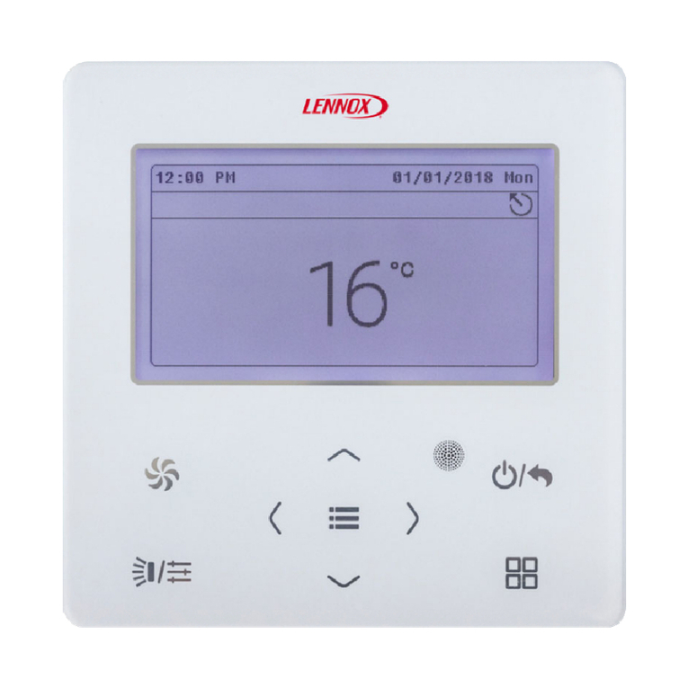
Your new LENNOX Thermostat has been designed to provide accurate control and displa of room temperature. In
addition, it will also displa all relevant information pertaining to our s stem.
The clearl marked buttons and informative displa make it extremel eas to understand and simple to use.
Please take a few moments to read the brief instructions and familiarise ourself with the various functions in order to obtain
maximum benefit from this trul unique electronic control.
This electronic control is organised into two integrated s stems: a terminal, installed in the room, and a power board for managing
the actuators in the electrical panel. The terminal is connected to the power board using a four-lead cable, thus greatl simplif ing
installation, with shield cable (supplied with the unit).
TERMINAL INSTALLATION
For correct installation the following warnings must be heeded:
Alwa s disconnect the power suppl before performing an operations on the board during assembl , maintenance or
replacement.
The terminal should be fastened to the wall verticall , allowing for air to circulate through the instrument's vent-holes, in order
to detect the correct ambient temperature
Avoid places where the measurement of the ambient temperature b the internal sensor ma be altered, such as outside walls,
near doors leading outside, in direct sunlight, etc.
The installation procedure is as following:
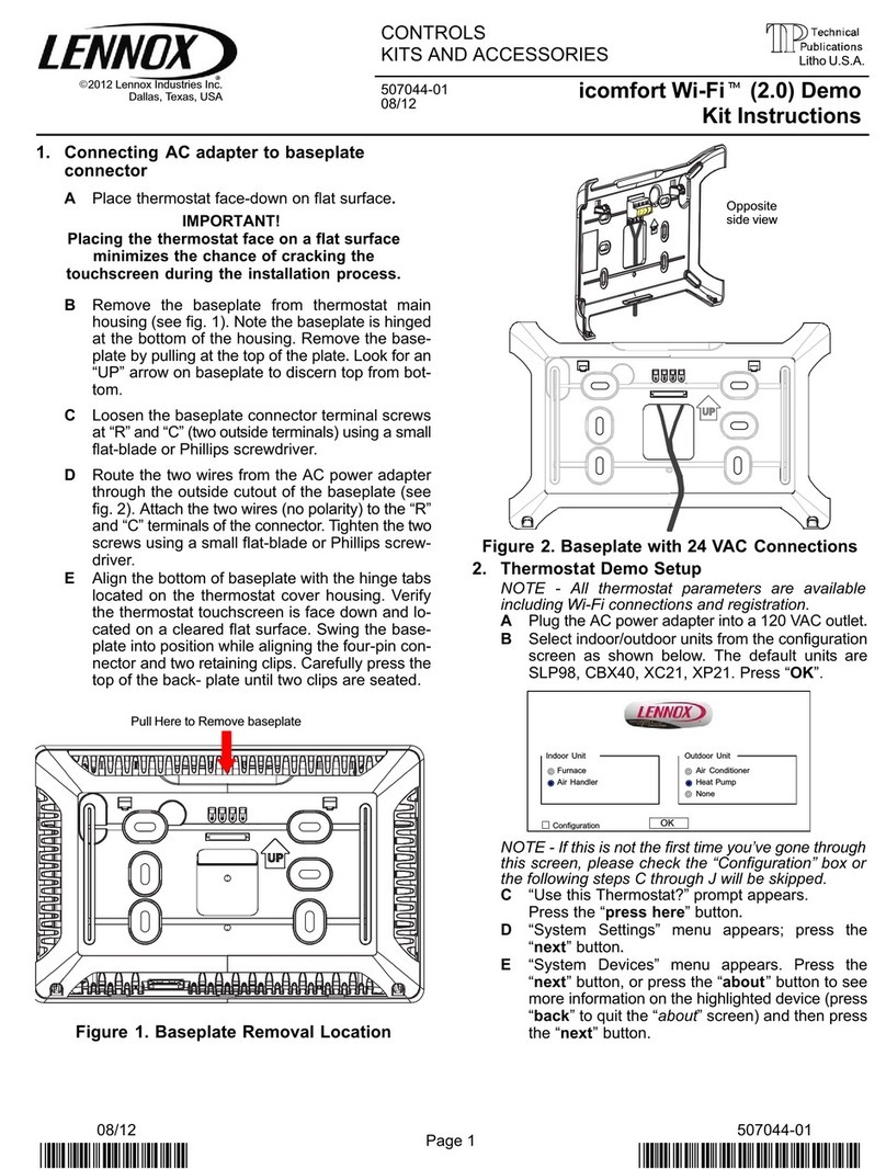
1º To detach the front panel of the terminal from the rear shell,
insert a flat-head screwdriver in the slot in the centre of the bottom
of the box and release the locking flap.
2º Raise the front panel using a hinge movement, using the
upper edge of the instrument as the pivot and raising the lower
edge.
3º To fasten the rear part of the box to the wall, use the mounting
holes on the shell.
Cable supplied with
the unit Maximum
length allowed is
15m
Power board
UNIT
4º Connect the cables to the
terminals on the electrical box, as
indicated in electrical diagram.
5º Finall , close the instrument, moving the front panel onto the rear shell with a hinge movement, in the opposite wa as used
for opening. First the long side of the front panel near the displa is snapped onto the rear shell, then the opposite side, being
careful that the terminal pins slide into their corresponding female terminals.
Sub-base Terminal-Thermostat
INSTALLATION GUIDE FOR CONTROL CABLE (TO AVOID INTERFERENCES):
Use the screened 15 m cable supplied with terminal (3 wires + screen).
Wire the cable separated from electrical power wiring b a ph sical distance of 500 mm.
Wire the cable separated from halogen lamps/fluorescent tube lighting... b a ph sical distance of 500 mm.
Wire the cable separated from radio frequenc sources such as radio transmitter... at least 500 mm.
NEVER WIND THE REMAINING CABLE AROUND, CUT THE CABLE BY THE TERMINAL END.
CONTENTS
TERMINAL-THERMOSTAT INSTALLATION AND UNIT CONFIGURATION
USER INTERFACE DESCRIPTION
SELECTING UNIT OPERATING MODE AND SET-POINT
PROGRAMMING ADJUSTMENT
ALARM CODES
UNIT PROTECTION DEVICES
PAGE
1
2
3-4
5
6
6
ON / OFF
ON / OFF
12
ON / OFF
KEY LOCK
AUTO
AUTODRY COOLHEAT FAN
COOL
TEMP.
HEAT
TEMP.
ROOM
TEMP.
TIMER ACTIVE SET TIMER SET CLOCK
MON TUE WED THU FRI SAT SUN
SLEEP
SWING
SLEEP MODE
SWING ON TIMER OFF TIMER
HOLD DAY HOUR MINUTE
CLOCK
SET TEMP
FAN
IMPORTANT Prior o making the electrical connections, set the switch or heat pump unit or or cooling
only unit.
NOT USED FOR CASSETTE UNITS. (See documentation or the unit)
HEAT PUMP
J_MODE
COOLING ONLY
(factor setting)
P.C.B.
J_MODE
J_MODE

