Lennox HP21 User manual

07/08 506146−01
*2P0708* *P506146-01*
Page 1
E2008 Lennox Industries Inc.
KITS COMMON TO HEATING AND
COOLING EQUIPMENT Litho U.S.A.
E2008
L
ennox
I
n
d
us
t
r
i
es
I
nc.
Dallas, Texas, USA 506146−01
07/08 HP21/HS21 CONTACTOR
REPLACEMENT KIT
INSTALLATION INSTRUCTIONS FOR REPLACEMENT CONTACTOR KIT
(43W56) FOR USE WITH HP21 AND HS21 UNITS
RETAIN THESE INSTRUCTIONS
FOR FUTURE REFERENCE
WARNING
Improper installation, adjustment, alteration,
service or maintenance can cause personal injury,
loss of life, or damage to property.
Installation and service must be performed by a
licensed professional installer (or equivalent) or a
service agency.
Shipping and Packing List
Package 1 of 1 contains the following
Item Description QTY
Contactor (3−pole 25A contactor with end switch) 48G5801 1
Contactor (3−pole 40A contactor) P−8−7716 1
Template (580104−01) to use as a locator for drilling holes
needed to install the two replacement contactors.
1
Wire ties 8
# 8−32 x 1/2 TFS mounting screws (P−8−9680) 6
6" long 18−gauge yellow wire 1
10" long 18−gauge blue wire 1
Wiring diagram sticker (single−phase) 537139−01 1
Wiring diagram sticker (three−phase) 537140−01 1
Shipping Damage
Check equipment for shipping damage. If you find any
damage, immediately contact the last carrier.
Application
This kit is to be used to replace the existing 5−pole
contactor with two new contactors in HS21 and HP21
single− and three−phase units.
Installation
CAUTION
Physical contact with metal edges and corners
while applying excessive force or rapid motion can
result in personal injury. Be aware of, and use
caution when working near these areas during
installation or while servicing this equipment.
WARNING
Electric Shock Hazard. Can cause
injury or death.
Unit may have multiple power
supplies. Disconnect all remote
electric power supplies before
opening access panel.
Unit must be grounded in accordance
with national and local codes.
Replace the contactor as follows:
1. Disconnect all electrical power to the unit. (The unit
may have multiple power supplies.)
2. Cut wire ties as necessary to allow enough wire length
to remove the 5−pole contactor from its location in the
unit. Remove as few wires as possible from the 5−pole
contactor. This will save time when wiring the new
contactors. Label any wires that must be
disconnected.
3. Use a 5/16" nut driver to remove the two 5/16" screws
that secure the 5−pole contactor into the unit. These
screws can be used to secure one side of the 3−pole,
25A replacement contactor.
4. Rotate the 5−pole contactor toward the right side of the
control box and remove the contactor from the unit.
5. Use the original contactor mounting holes as
reference and apply the provided contactor template
sticker to the back of the control box.
6. Drill 1/8" pilot holes as shown on the template. See
figure 1.
EXISTING
HOLES FROM
5−POLE
CONTACTOR
NEW HOLES
REQUIRED FOR
REPLACEMENT
CONTACTOR
NEW HOLES
REQUIRED FOR
REPLACEMENT
CONTACTOR
3−Pole, 25A Contactor
with End Switch 3−Pole, 40A Contactor
Figure 1. Template Sticker (580104−01)

Page 2
7. Wiring connections for 3−pole, 25A contactor with end
switch:
a − Single−Phase units: Locate the 10" long 18−gauge
blue wire and connect one end to the normally
closed contacts (NC) of the end switch. Move the
wires from the existing 5−pole end switch to the
end switch terminals of the replacement 3−pole,
25A contactor (Com to Com, NO to NO and NC to
NC).
b − Three−Phase units: Move the wires from the
existing 5−pole end switch to the end switch
terminals on the new 3−pole, 25A contactor (Com
to Com and NC to NC).
NOTE − The provided 10" long 18−gauge blue wire
is not wired to the end switch on the three−phase
units.
8. Install the 3−pole, 25A contactor with the end switch on
the left side of the template as shown in figure 1.
9. Install the 3−pole 40A contactor on the right side of the
template as shown in figure 1.
10. Locate the 6" long 18−gauge yellow wire and install
each end to the common side terminals of both
replacement contactor 24 volt coils. See the wiring
diagrams in figures 2 through 7.
11. Contactor coil wiring:
a − Single−Phase units: Locate the 10" long 18−gauge
blue wire installed on the normally closed contacts
(NC) of the end switch. Route the other end of the
blue wire to the Hot coil terminal on the 3−pole, 40A
contactor (K226). See figures 2 through 6.
b − Three−Phase units: Move the wires that are on the
existing 5−pole coil onto the coil terminals of the
new 3−pole, 25A contactor. Locate the 10" long
18−gauge blue wire and connect one side of the
wire to the Hot coil terminal on the 3−pole, 40A
contactor and the other side to the Hot coil
terminal of the existing 3−pole, 25A contactor
(K69).
12. Confirm end switch and 24 volt coil wiring.
13. Transfer line voltage wiring from the 5−pole contactor
to the two 3−pole replacement contactors. See the
wiring diagrams in figures 2 through 7.
14. Confirm all electrical connections are tight.
15. Apply applicable wiring diagram on dry clean surface
beside existing factory wiring diagram.
16. Apply line and low voltage power to unit.
17. Perform operation sequence check. (Use operation
sequence in these instructions as reference.)
18. Confirm that all access panels are installed, all
controls are correctly set and operating mode has
been properly selected.
Compressor Contactor Energized
Compressor
Speed Single Phase Three Phase
Low K1 and K226 K1
High K1 and K69 K69 and K226
Wiring Diagrams
Point−to−point wiring diagrams which detail the changes
required during kit installation in single−phase units are
given in figures 2 and 3. See figure 4 for a schematic
diagram for a single−phase unit after the kit has been
installed.
Point−to−point wiring diagrams which detail the changes
required during kit installation in three−phase units are
given in figures 5 and 6. See figure 7 for a schematic
diagram for a three−phase unit after the kit has been
installed.

Page 3
EXISTING 5−POLE CONTACTOR WIRING
WIRING FOR TWO REPLACEMENT 3−POLE CONTACTORS
3 POLE, 25A 3 POLE, 40A
Figure 2. Single−Phase Low Voltage

Page 4
EXISTING 5−POLE CONTACTOR WIRING
WIRING FOR TWO REPLACEMENT 3−POLE CONTACTORS
40A
Figure 3. Single−Phase High Voltage

Page 5
*
*CMC1 used in heat pumps only.
Figure 4. Single−Phase Wiring Schematic

Page 6
EXISTING 5−POLE CONTACTOR WIRING
WIRING FOR TWO REPLACEMENT 3−POLE CONTACTORS
3 POLE, 25A 3 POLE, 40A
−
Figure 5. Three−Phase Low Voltage

Page 7
EXISTING 5−POLE CONTACTOR WIRING
WIRING FOR TWO REPLACEMENT 3−POLE CONTACTORS
40A
25A
Figure 6. Three−Phase High Voltage

Page 8
*CMC1 used in heat pumps only.
*
Figure 7. Three−Phase Wiring Schematic

Page 9
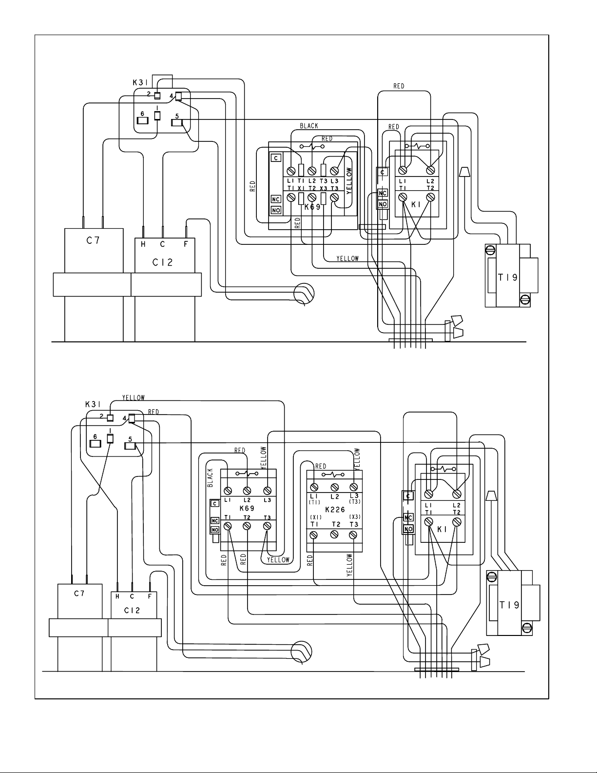
Single−Phase Compressor Operation
Checklist
LOW SPEED
1. First−Stage Demand: If all safety circuits check out,
TSC (A14) energizes JP44−9.
2. Contactor K1 and K226 are energized. K1−2 contacts
open to de−energize the crankcase heater. All other K1
contacts close to start outdoor fan and to begin
compressor low speed operation. K226−1 contacts
close to begin compressor low speed operation.
3. Compressor (B1) terminal 1 and the outdoor fan circuit
are energized by K1 contacts L1−T1. Compressor
terminal 7 is energized by contacts K1 terminals L2−T2
and K226 terminals T1−L1. Compressor terminal 8
(low speed start winding) is energized through
contactor K1 terminals L2−T2, through the run and
start capacitors, and to contactor K226−1 terminals
L3−T3.
4. As the compressor nears proper speed, potential relay
K31 energizes and K31 terminals 1–2 open.
HIGH SPEED
1. Second Stage Demand: If all safety circuits check out,
TSC (A14) energizes JP44−8.
2. Contactor K69 energizes and K69−2 auxiliary contacts
close to energize contactor K1 coils and de−energize
K226 contactor coil. K1−2 contacts open to
de−energize the crankcase heater. K1 contacts L1−T1,
L2−T2 and L3−T3 close, while K226 contacts L1−T1
and L3−T3 open.
3. Compressor (B1) terminal 3 (high speed start winding)
is energized by contactor K1 terminal L2−T2, through
the run and start capacitors and through contactor K69
terminals L3−T3. Compressor terminal 2 is energized
by contactor K1 terminal L2−T2. Compressor terminal
7 is energized by K1 contactor terminals L1−T1
through contactor K69 terminals L1−T1.
4. As the compressor nears proper speed, potential relay
K31 energizes and K31 terminals 1–2 open.
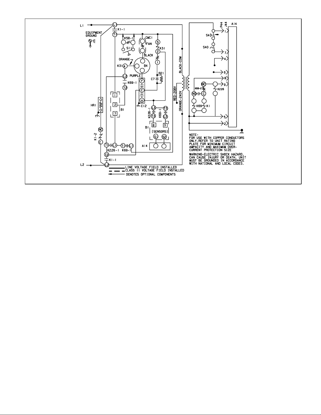
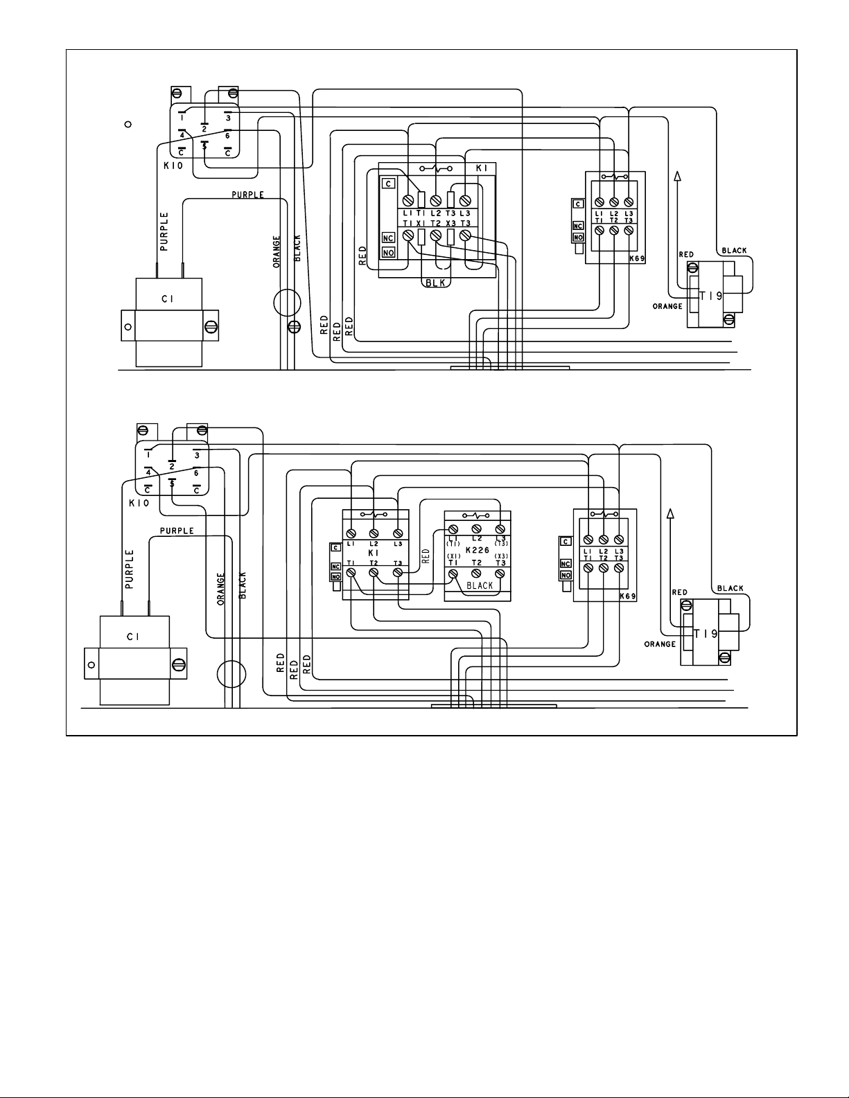
Three−Phase Compressor Operation
Checklist
LOW SPEED
1. First Stage Demand: Low speed (Y1) room thermostat
demand energizes outdoor fan relay and JP44−6.
K10−1 switches to energize the outdoor fan and
de−energize the compressor crankcase heater.
Outdoor fan begins operating immediately.
2. If all safety circuits check out, TSC (A14) energizes
JP44−9. Contactor K1 coil is energized through K69−2
NC end switch contacts.
3. After appropriate time delay, K1 contacts close to
cycle compressor onto low speed. K226 contacts
remain open to disconnect the high speed wiring
circuitry.
4. Compressor (B1) terminal 1 is energized by K1
terminal L1−T1. Compressor terminal 2 is energized by
K1 terminals L2−T2. Compressor terminal 3 is
energized through K1 terminal L3−T3.
HIGH SPEED
1. Second Stage Demand: High speed (Y2) room
thermostat demand energizes JP44−4.
2. If all safety circuits check out, TSC (A14) energizes
JP44−8.
3. Contactors K69 and K226 energize through K1−2 end
switch contacts. K69 and K226 contactor coils close
for compressor high speed operation. Compressor
terminal 4 is energized by contactor K69 terminals
L1−T1. Compressor terminal 6 is energized by
contactor K69 terminals L2−T2. Compressor terminal
5 is energized by K69 contactor terminals L3−T3.
Compressor terminals 1, 2 and 3 are connected
through K226 contacts L1−T1 and L3−T3.

Page 10
Reference Information
UNIT INFORMATION MANUALS
Unit information manuals are available on DaveNet for
both the HS21 and HP21.
1. HS21 Unit Information is CORP 9406−L3.
2. HP21 Unit Information is CORP 9434−L12.
OPERATION SEQUENCE − COMPRESSOR
Single-Phase Compressor Start−Up
1. Figure 8 illustrates windings of a single-phase
two−speed compressor. This compressor has a
two−speed capacitor-start, capacitor-run motor. For
starting, the start and run capacitors are in parallel to
provide the proper starting torque. The start capacitor
is disconnected by the start relay when the
compressor comes up to speed. The run capacitor
remains connected to the start winding and the motor
runs as a two-phase induction motor with improved
power factor and torque characteristics provided by
the capacitor.
MOTOR LEAD TERMINALS
LOW SPEED
START WINDINGS
HIGH SPEED
START WINDINGS
COMMON
RUN WINDINGS
RUN
CAP.
START
CAP.
START RELAY
8
3
7
2
1
MOTOR LEAD TERMINALS
COMMON
8
3
7
2
1
HIGH SPEED
START WINDINGS
RUN WINDINGS
LOW SPEED
START WINDINGS
START RELAY
START
CAP.
RUN
CAP.
SINGLE-PHASE MOTOR WINDINGS LOW SPEED
SINGLE-PHASE MOTOR WINDINGS HIGH SPEED
Figure 8. Single−Phase
2. Low speed compressor operation is provided by
powering the run windings (internally connected in
series) from terminals 1 (common) and 7. The
windings form a four-pole motor operating at 1800
RPM. The four low speed start windings are in series
and are connected to terminals 1 (common) and 8.
They are used with the start and run capacitors and
start relay to start and bring the motor up to speed.
3. High speed compressor operation is provided when
the run windings are connected in parallel; terminals
1 (common) and 7 to L1 and terminal 2 to L2. The
windings form a two-pole motor operating at 3600
RPM. The two high−speed start windings are in series
and connected to terminals 1 (common) and 3.
Three−Phase Compressor Start−Up
1. Figure 9 illustrates the windings of three-phase,
two-speed compressors. These compressors are
two-speed, three-phase induction motors. Capacitors
are not needed to provide the proper phase and torque
characteristics.
2. Low speed operation is provided when the motor
windings are connected in a series Delta circuit. The
motor operates at 1800 RPM.
3. High speed operation is provided when the motor
windings are connected in a parallel Delta circuit.
THREE-PHASE MOTOR WINDINGS LOW SPEED
SERIES DELTA" CIRCUIT
THREE-PHASE MOTOR WINDINGS HIGH SPEED
PARALLEL DELTA" CIRCUIT
L1
L2
L3
T1
T4
T3
T5
T2
T6
L1
L2
L3
T4
T3
T5T2T6
T1
COMPRESSOR
CONTACTOR K226
(Normally open contacts shown
in energized/closed position)
Figure 9. Three−Phase
Other manuals for HP21
2
This manual suits for next models
1
Table of contents
Other Lennox Industrial Equipment manuals

Lennox
Lennox OHR23 Series User manual

Lennox
Lennox GCS16 Series User manual

Lennox
Lennox TAA Series Installation and operation manual

Lennox
Lennox TSA S4 Series User manual

Lennox
Lennox SYSTEMA EOLO LXC 50 User manual

Lennox
Lennox EL195UHNE Series User manual

Lennox
Lennox G21Q3-40 Installation and operation manual

Lennox
Lennox 10GCS Series User manual

Lennox
Lennox COMFAIR-HH User manual

Lennox
Lennox G26 Series User manual