Lenz Digital Plus SET010 User manual

1
B.B.10.0024
Erste Schritte
First Steps
Premier démarrage
SET010
Art. Nr. / art. no. 60110
1. Auflage / 1st edition 0415

2 Erste Schritte SET010
Willkommen!
Diese Betriebsanleitung soll Ihnen die ersten Schritte mit dem
SET010 erklären.
Ausführliche Informationen zum Anschluss der Komponenten des
SET010 und deren Bedienung finden Sie in den Betriebsanleitungen
der einzelnen Geräte.
Wenn Sie Fragen haben, auf die Sie auch nach Durcharbeit dieser
Informationen keine Antwort finden, so helfen wir Ihnen gerne weiter.
Auf vier verschiedene Arten können Sie mit der Lenz Elektronik
GmbH Kontakt aufnehmen:
Postanschrift:
Lenz Elektronik GmbH
Vogelsang 14
D-35398 Giessen
Telefon:
++49 (0) 6403 900 133
Wann Sie uns hier erreichen,
erfahren Sie aus der Ansage
Fax:
++49 (0) 6403 900 155
Email:
Alles da?
Bitte prüfen Sie, ob alles in der Verpackung enthalten ist:
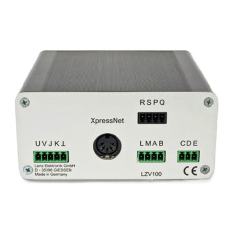
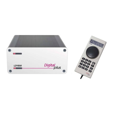
LZV100 Gerät
Handregler LH010
Anschlusskabel für LH01
Information LH01
Information LZV100
Info "Erste Schritte SET010 (dieses Heft)
Sollte ein Teil fehlen, wenden Sie sich bitte Ihren Fachhändler zur
Nachlieferung.

3
D
1 Wichtige Hinweise, zuerst durchlesen!
Die Komponenten des SET010 des
Digital plus by Lenz
®
Systems
wurden vor Auslieferung einem intensiven Test unterzogen. Lenz
Elektronik GmbH garantiert für einen fehlerfreien Betrieb, wenn Sie
die folgenden Hinweise beachten:
Die Komponenten des SET010 dürfen nur mit anderen Komponenten
des
Digital plus by Lenz
®
Systems zusammen verwendet werden. Eine
andere Verwendung, als die in den Betriebsanleitungen dieser
Komponenten beschriebene, ist nicht zulässig und führt zu Verlust der
Gewährleistung. Verwenden Sie die im SET010 enthaltenen Geräte
nur entsprechend den in den Betriebsanleitungen gemachten
Angaben.
Wenn Sie bei Problemen mit uns Kontakt aufnehmen möchten, sollten
Sie uns neben der Problembeschreibung folgende Informationen
mitteilen:
Versions- und Servicenummer des Handreglers LH010
Versions- und Servicenummer der LZV100
Bezeichnung, Versions- und Servicenummer der weiteren
Komponenten mit denen das Problem auftritt.
Dies hilft unserem Service bei der Problembehebung, vielen Dank.

4 Erste Schritte SET010
2 Funktionsumfang des SET010
Mit dem SET010 können Sie:
bis zu 9999 Digitalloks und
eine konventionelle Lok steuern,
bis zu 29 Funktionen in Lokdecodern schalten,
Funktionen in Lokdecodern auf Dauer- oder Momentbetrieb
einstellen,
Fahrstufenmodus zu den Lokadressen einstellen,
Doppeltraktionen zusammenstellen, steuern und wieder auflösen,
Programmieren während des Betriebs (PoM),
Einstellen der Lokadresse auf dem Programmiergleis,
Bis zu 999 Weichen und andere Magnetartikel schalten,
konstante Zugbeleuchtung nutzen,
bis zu 30 weitere Bediengeräte anschließen,
und vieles mehr.
Genaue Informationen finden Sie in den Betriebsanleitungen zur
LZV100 sowie zum LH010. Diese Informationen liegen dem SET010
ebenfalls bei.

5
D
3 Systemaufbau
Eingabe Fahren und Schalten:
Zentrale
mit
Verstärker
LZV100
Rückmelder Schalt-
decoder
Lok-
decoder
Handregler
LH100
Handregler
LH01
Interface
LAN/USB
Computer
Rückmeldung
2 Drähte (R,S)
XpressNet: 4 Drähte (L,M,A,B)
Programmiergleis (P,Q)
zum Gleis (J,K)
Trafo (U,V)
Diese Grafik zeigt den einfachen Systemaufbau des
Digital plus by Lenz ®Systems.

6 Erste Schritte SET010
4 Anschluß und Inbetriebnahme
Die Anschlüsse an der LZV100 sind als steckbare Schraubklemmen
ausgeführt.
4.1 Anschluß der LZV100 an die Gleise
Verbinden Sie die Klemmen J und K der
LZV100 mit dem Anschlußgleis Ihrer
Modellbahn:
Anschluß 2-Leiter-Gleise
Gleisanschluss der LZV100
Anschluß Gleis mit
Mittelleiter
Es dürfen keine Kondensatoren zur Funkentstörung in der
Gleisanlage eingebaut sein. Diese Kondensatoren sind nur beim
konventionellen Betrieb zur Funkentstörung notwendig. Beim
Digital plus System verfälschen sie jedoch das Datenformat und die
einwandfreie Datenübertragung wird beeinträchtigt.

7
D
4.2 Anschluß des Handreglers LH01 an die LZV100
1.
Stecken Sie den Westernstecker des mitgelieferten
Anschlusskabels in die Buchse des LH01.
2.
Stecken Sie den 5-poligen DIN-Stecker in die 5-polige
DIN-Buchse an der Rückseite Ihrer LZV100

8 Erste Schritte SET010
4.3 Anschluß der LZV100 an den Transformator
Verbinden Sie die Klemmen U und V der LZV100 mit den
Anschlussklemmen des Transformators TR150.
Die Anschlüsse U,V zur Stromversorgung der LZV100
4.4 Inbetriebnahme
Stecken Sie den Netzstecker des Transformators in die Steckdose.
Wir gehen im Folgenden davon aus, dass Sie eine Lok mit der
Adresse 3 einsetzen. Stellen Sie die Lokomotive mit eingebautem
Decoder auf die Gleise Ihrer Modellbahn.

9
D
4.5 Erste Fahrt
Aktion
Display
Erläuterung
Bei der ersten Inbetriebnahme wird
die werkseitig eingestellte
Lokadresse 0003 im Display des
LH01 angezeigt.
Durch Drehen am Drehgeber
können Sie sofort die Fahrstufe für
diese Lokadresse ändern, jetzt wird
die Fahrstufe der Lok angezeigt.
Drehen im Uhrzeigersinn erhöht die
Fahrstufe
Drehen gegen den Uhrzeigersinn
vermindert die Fahrstufe.
Wenn Sie die Fahrtrichtung Ihrer Lokomotive ändern wollen…
… stellen Sie die Fahrstufe auf 0
und …
… drücken auf die Mitte des
Drehknopfs. Die Änderung der
Fahrtrichtung wird angezeigt.
Mit den Tasten A, B und C können Sie Lokfunktionen F0, F1 und F2
schalten.

10 Erste Schritte SET010
4.6 Notaus
Aktion
Display
Erläuterung
Drücken Sie auf die Mitte des Drehgebers,
und halten Sie diesen gedrückt bis "AUS"
im Display erscheint.
Die Gleisspannung ist nun ausgeschaltet.
Um die Gleisspannung wieder einzuschalten,
drücken Sie erneut auf die Mitte des
Drehknopfs bis in der Anzeige die Meldung
"EIN" erscheint.
Während des "AUS" Zustands können Sie durch Drücken der
'Esc'-Taste die aktuell gewählte Lokadresse anzeigen.
Weitere ausführliche Hinweise zur Bedienung des LH01 finden Sie in
der Broschüre "Information LH01", die dem SET010 beiliegt.

11
E
Welcome!
This operating manual is to explain your first steps with SET010.
You will find detailed information on how to connect and use the
components of the SET010 in the operating manuals of the respective
devices.
If you still have unanswered questions even after reading this
operating manual, then please contact us. There are four different
ways of contacting Lenz Elektronik GmbH:
Postal
address:
Lenz Elektronik GmbH
Vogelsang 14
D-35398 Giessen
Telephone:
++49 (0) 6403 900 133
The recorded message will
inform you of times when we
are available for consultation.
Fax:
++49 (0) 6403 900 155
E-mail:
All present?
Please check whether all the components have been delivered:
LZV100 device
Manual control LH01
Cable for LH01
Information LH01
Information LZV100
Info "First Steps SET010" (this booklet)
If any component is missing, please ask your specialist supplier for a
supplementary delivery.

12 First Steps SET010
1 Important advice, please read first!
The components of the SET010 of the
Digital plus by Lenz
®
system
were submitted to intensive testing before delivery. Lenz Elektronik
GmbH guarantees fault-free operation if you follow the advice given
below:
The components of the SET010 are authorised for operation only with
other components of the
Digital plus by Lenz
®
system. Any use other
than the one described in these operating manuals is not permitted
and all guarantees become invalid if the SET010 is used in an
inappropriate way. Only use the devices contained in the SET010 in
accordance with the information given in the operating manuals.
If you have any problems, just contact us, stating the following
information together with a description of the problem:
Version and service number of the manual control LH01.
Version and service number of the LZV100.
Designation, version and service number of other components
with which you experience the same problem.
This will help our service department to resolve the problem. Thank
you.

13
E
2 Range of functions of the SET010
With the SET010 you may:
control up to 9999 digital locomotives and
1 conventional locomotive
switch up to 29 functions in locomotive decoders
set functions in locomotive decoders to continuous or
instantaneous operation
set the running notches mode to the locomotive addresses
assemble, control and delete double tractions
program in operational mode
programming of the loco's address on the programming track
switch up to 999 points and other magnetic articles
use constant train lighting
connect up to 30 other operating devices
and much more.
You will find more detailed information in the manuals of the LZV100
and LH01. These manuals are included in the SET010.

14 First Steps SET010
3 System design
command station
with
amplifier
LZV100
Feedback
modul
Switch
decoder
Locomotive
decoder
Input driving and switching:
manual control
LH100
manual control
LH01
Interface
LAN/USB
Computer
feedback
2 wires (R,S)
XpressNet: 4 wires (L,M,A,B)
Programming track (P,Q)
To the track (J,K)
Transformer (U,V)
This graphic presentation shows the simple system design of the
Digital plus by Lenz system.

15
E
4 Connection and initial operation
All the LZV100 connections are designed as pluggable terminal
screws.
4.1 Connecting the LZV100 to the tracks
Connect terminals J and K of the LZV100 to
the siding track of your model railway:
Connection: 2-wire tracks
The LZV100 track connection
Connection: track with
neutral wire
No radio interference suppression capacitors may be installed in the
track system. These capacitors are necessary only for the
interference suppression in conventional operation. If used with the
Digital plus system, however, they would only distort the data format
and interfere with the fault-free transmission of data.

16 First Steps SET010
4.2 Connecting the manual control LH01 to the
LZV100
1.
Connect the RJ45 plug to the LH01.
2.
Connect the 5-pole DIN plug oft he cable into the LZV100

17
E
4.3 Connecting the LZV100 to the transformer
Connect terminals U and V of the LZV100 to the connecting terminals
of the transformer TR100 (or TR200)
Connections U,V to the power supply of the LZV100
5 Initial operation
Plug the mains plug of the transformer into the mains plug socket.
We assume in this example that you are operating a locomotive with
the address 3. Place the locomotive with an installed decoder on the
tracks of your model railway system.

18 First Steps SET010
5.1 First run
Aktion
Display
Erläuterung
With initial power up the locomotive
address 0003 is shown in the
display.
Turning the knob changes the speed
for this locomotive address. The
display shows now the speed-step.
Turning the knob counterwise rises
the speed step.
Turning the knob counter-clock
lowers the speed step.
If you wnat to change the running direction oft he locomotive…
… set the speed to 0 and …
… press the middle oft h knob. The
change oft he direction is
displayed.
With pushbuttons A, B und C you may switch the locomotive functions
F0, F1 and F2.

19
E
5.2 Emergency Stop
Aktion
Display
Erläuterung
Press and hold the middle oft he knob until
"AUS" ist displayed.
Now the track voltage is switched off.
To switch on the track voltage again, press
the middle oft he knob again until "EIN" is
displayed.
While "AUS" is displayed, the active locomotive address can be
displayed by pressing the 'Esc'-button
More detailed information about the usage oft he LH01 you'll find in
the "Information LH01".

20 SET010
Nicht geeignet für Kinder unter 3 Jahren wegen verschluckbarer Kleinteile. Bei
unsachgemäßem Gebrauch besteht Verletzungsgefahr durch funktionsbedingte Kanten
und Spitzen! Nur für trockene Räume. Irrtum sowie Änderung aufgrund des technischen
Fortschrittes, der Produktpflege oder anderer Herstellungsmethoden bleiben
vorbehalten. Jede Haftung für Schäden und Folgeschäden durch nicht
bestimmungsgemäßen Gebrauch, Nichtbeachtung dieser Gebrauchsanweisung, Betrieb
mit nicht für Modellbahnen zugelassenen, umgebauten oder schadhaften
Transformatoren bzw. sonstigen elektrischen Geräten, eigenmächtigen Eingriff,
Gewalteinwirkung, Überhitzung, Feuchtigkeitseinwirkung u.ä. ist ausgeschlossen;
außerdem erlischt der Gewährleistungsanspruch.
Not suitable for children under three because of the danger of their swallowing the small
constituent pieces. Improper use can result in injury by functionally necessary points
and edges. For use only in dry areas. We reserve the right to make changes in line with
technical progress, product maintenance or changes in production methods. We accept
no responsibility for errors which may occur for similar reasons. We accept no
responsibility for direct or indirect damage resulting from improper use, non- observance
of instructions, use of transformers or other electrical equipment which is not authorised
for use with model railways, or transformers or other electrical equipment which has
been altered or adapted or which is faulty. Nor can we accept responsibility when
damage results from unsupervised adjustments to equipment or from acts of violence or
from overheating or from the effects of moisture etc.. Furthermore, in all such cases
guarantees become invalid.
Vogelsang 14
35398 Giessen
Hotline: 06403 900 133
Fax: 06403 900 155
www.digital-plus.de
Email: info@digital-plus.de
Diese Betriebsanleitung bitte für späteren Gebrauch aufbewahren!
Keep this operation manual for future reference!
This manual suits for next models
1
Table of contents
Languages:
Other Lenz Control System manuals